BGU FSW 4.5 M User guide

Seite 1
Carefully read these instructions
before starting and using your log winch!
Original Instruction Manual
Südharzer Maschinenbau GmbH
99734 Nordhausen, Helmestraße 94
Service Tel. 0 36 31 / 62 97 104 • Fax 0 36 31 / 62 97 111
Internet: www.bgu-maschinen.de
e-mail: [email protected]
Mechanical Logging Winch
FSW 4.5 M / 5.5 M
- Set-up & installation
- Use
- Maintenance
- Accessories

Seite 2
Südharzer Maschinenbau GmbH
Helmestr. 94
99734 Nordhausen
Tel: 0 36 31 / 62 97-0 Fax: 0 36 31 / 62 97 111
CE – Statement of Compliance
to the EC Machines Directive No. 2006/42, Annex II A and (Low Voltage)
Directive 2004/108
We hereby declare that the equipment described in this manual responds in full to the actual version
brought on the market. We, the manufacturer further declare that this equipment was duly designed and
manufactured in accordance with the actual European Safety and Health Standards settled by the relevant
EEC directives as well as the latest electromagnetic standards issued by the European Council of 3.5.89 and
later enforced by all member states. This statement of compliance does not apply to customer modifications
of the equipment without manufacturer’s written approval. The manufacturer shall not be responsible for
such modified equipment and machines.
Machine type:: Logging winch
Models: Mechanical FSW 4.5 M / 5.5 M
Production No.: see model label
Applicable European Standards: EC Machine Directive (EC 42/2006)
and following amendments and additions
Low Voltage) Directive 2004/108
Other applicable Standards
and technical specifications: EN ISO 12100-1,
EN ISO 12100-2,
EN ISO 4254-1,
EN ISO 14492-1
29.12.2009
................. ....................................
Date Jörg Kernstock
Director
Official user's language: English (User’s release)

Seite 3
List of contents
Seite
1. General information.................................................................................................... 4
1.1 Delivery and transport claims .............................................................................................. 4
2. Safety pictograms and warning labels..................................................................5
3. Safety rules ................................................................................................... 6/7
4. About PTO ................................................................................................. 8
5. Operation.......................................................................................................................... 8
5.1 PTO shaft requirements ........................................................................................ 8
5.2 Connecting the winch to the tractor ...................................................................................... 8
5.3 Connecting the winch to the tractor....................................................................................... 9
5.4 Wire rope installation ..................................................... ..................................................... 9
5.4.1 Checking the wire rope quality.............................................................................................. 10
5.4.2 Spooling of the wire rope......................................................................................................... 10
5.4.2 Unspooling of the wire rope..................................................................................................... 10
5.5 Skidding operations.............................................................................................................. 10
5.6 Settings ................................................................................................................................ 11
5.6.1 Clutch................................. ................................................................................................. 11
5.6.2 Pre-braking arrangement...................................................................................................... 11
5.6.3 Brake.................................................................................................................................... 12
5.6.4 Stretching of the drive chain................................................................................................. 13
5.7 Lubrication....................................................................................................................... 13/14
5.7.1 Visual and functional tersting before first use........................................................................ 15
5.7.2 Effects of overloading or misusing the winch........................................................................ 15
6. Technical specifications.............................................................................................. 16
7. Warranty........................................................................................................................... 16
8. Spare parts list............................................................................................................... 16
9. Warranty for new wire ropes.................................................................................... 20

Seite 4
User's manual
1. General information
Dear customer,
Thank you very much for your trust and preference in choosing our equipment and joining the number of
our best customers in the world. We are confident that our equipment will be up to all your expectations and
assure you a long lasting quality and performance.
Our log winches are available in two different versions of different skidding force.
FSW 4.5 pull force 4,5 tons mechanical operation system
FSW 5.5 pull force 5,5 tons mechanical operation system
All versions are designed and conceived for farming and logging applications. Any other use shall be
considered non-compliant application.
The manufacturer accepts no responsibility for damages caused by non-compliant application. In this case
the operation of the machine is completely at user’s risk.
1.1 Delivery and transport claims
Upon delivery of the machine please check for visual machine damages such as damaged packing or scrat-
ched buckled parts. If so, make a remark on all copies of the delivery bill before signing for acceptance.
The truck driver must absolutely sign all copies of the delivery bill. Should your shipper or the truck driver re-
fuse to accept your claim, fully reject delivery and make sure to inform us (the manufacturer) immediately.
No claims shall be taken into account by the shipper or by the insurance company, if a reservation note is
not made on the delivery bill.
All transport damages must be notified within latest 2 days from delivery. Therefore delivery must be collected
and inspected within this term. Later claims shall be disregarded. In case of assumed but not visually clear
transport damages make sure to mark the following sentence on the delivery bill:” Reserved delivery due to
assumed transportation damages”.
Insurance and shipping companies act with extreme caution in case of transport damages and sometimes
refuse to accept any responsibility. Please make sure to provide clear and exhaustive evidence (photos) of
the claimed damages.
Thank you in advance for your help and understanding in this matter.

Seite 5
2. Safety pictograms and warning labels
1. Warning label
„Never operate or install a winch without reading or understan-
ding the operator’s manual“
This label reminds the user about the importance of reading and
understanding the instructions of the manufacurer and getting
familiar with the winch before first use.
2. Danger sing
“Keep yourself and others at safe distance from the dangerous
area!”
This label reminds operator and bystanders of the dangerous
area between the tractor and the winch.
3. Machine safety label
“ max 540 min”
This label shows the max number of revolutions and the direc-
tion of rotation of the driveshaft connecting the winch to the
tractor.
4. Danger sign
„No hoisting!“
5. Machine operation sign
“Disconnect the winch, read and comply with manufacturer’s
maintenance instructions.”
This is to remind the operator to familiarize himself with the
maintenance procedures of the manufacturer contained in the
user’s manual.
6. Identification label
„Product identification“
This label shows the company details of the manufacturer and
the main machine technical data.
7. Identification label
„BGU-Maschinen” manufacturer’s logo
8. Operator's safety label
„Wear steel-toe safety shoes”

Seite 6
3. Safety rules
Strictly perform installation, set-up, maintenance, cleaning and transportation of the winch with the
power switched off and all moving parts motionless and secured against accidental operation.
The user shall strictly comply with these operation , set-up, maintenance, repair and trouble-shooting
instructions in order to assure safe operation and no damages to the equipment. Moreover, we recommend
to let the machine be run only and strictly by trained and skilled staff who must be familiar with the applicable
occupational safety and health administration rules as well as applicable transportation rules.
No person under school leaving age should operate a forestry winch. Those who have reached school
leaving age but are below the age of 18 may operate a forestry winch if supervised by a competent person
of 18 years or over.
The machine shall be installed and kept in a suitable location selected by the customer for safest operation.
The working area around the machine must be kept as clear as possible from surrounding obstacles and
slippery foundation floors should be duly treated (do not use saw dust or wood ash for this purpose).
Make sure that the equipment stands on a safe stable foundation.
- Due and proper illumination of the working site must be provided at all times.
- Set up the machine on a firm surface and ensure that a wide but confined area is available around the
machine assuring maximum working freedom.
- Mind all operation sings and warning labels on the winch and comply with the instruction given herein.
- Operators must wear steel toe safety shoes, working protective gloves, protective helmet and snug-fitting,
tear-resistant work cloths.
- Never leave the forestry winch unattended
- Before switching power on and putting the winch to work make sure that there are no bystanders in the
dangerous area and that you have good and clear visibility on the work area.
- It very dangerous and strictly prohibited to sit/stand on the winch while transporting it.
- Provide due and correct mounting of the winch.
- Make sure to comply with driving speed requirements for the specific road conditions. Use caution when
changing direction or turning while winching uphill, downhill or across slopes.
- Do not stand in the dangerous area. Assure that nobody stands inbetween winch and tractor, unless the
tractor is safely braked and blocks have been put underneath the wheels to avoid accidental moving.
- Do not remove nor start handling timber before the winch has come to a complete stop.
- Periodically check that all screws and fixations are tightly in place.
- Before putting the winch to work perform a visual checkup of the overall conditions and let a skilled technicial
overhaul and service your winch at least once a year.
- It is strictly prohibited to use the winch for any other application than mentioned in this manual.
CAUTION: do not use the winch for hoisting applications! (Figure 5)
- Make sure that power is fully disconnected from the winch and that the tractor has been switched off before
performing any repair or work on the winch.
- Never operate the winch without its safeties and protections duly in place.
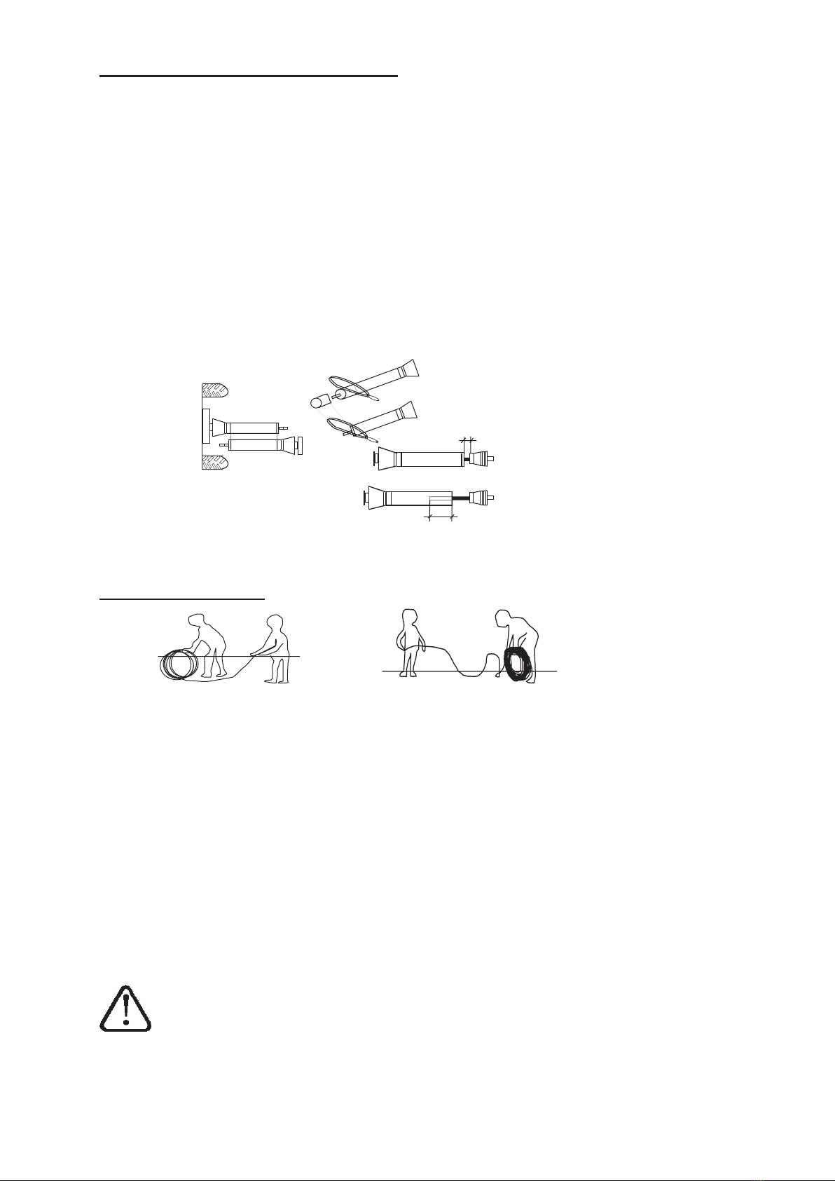
- Strictly use wire rope of adequate crush resistance, strength and quality. Provide for immediate wore rope
replacement, if any fault or anomaly is detected.
- Be sure that your wire rope length provides for a free gap to the upper drum profile of least 1.5 the rope
diameter when fully spooled. In other words, when the rope is fully spooled there should be space left on
the drum for at least two more coils.
- Make sure that your helpers do not put any extra load on the winch without prior informing the tractor
driver.
- Strictly operate the winch from a safe place, at safety distance from the load, the rope and such other
dangers as unfelled trees. The driver seat accounts as a safe place only if a safety screen is provided to
separate the winch from the tractor in such a way that it may not be removed or bypassed.

Seite 7
- CAUTION: it is very dangerous to stand in front of a tree to be felled and winched away. (Figu-
re 1)
( Figure 1) ( Figure 2)
- Winching with a pulley originates a three-sides dangerous area where none is allowed to stand
during winching operations. (Figure 2)
- Never exceed the max admissible pull angle of 30° (Figure 3).
- CAUTION: tip-over risk (Figure 4) when winching on rough terrain or exceeding the maximum
admissible pull angle.
( Figure 3) ( Figure 4) ( Figure 5)
Keep away from the dangerous area!
- You and your helper must establish clear and precise hand signals and review them so everyone clearly
understands.
Pull Stop Release rope
- If your winch is equipped with lower snatch block, use it also for pulling operations.
- The operator should monitor the load throughout the entire pulling operation. Although winches are one-
man equipment, you should never work alone and a second person should be ready to help in the event
of lack of full visibility.
- Attach your winch to any tractor equipped with road transport tires to avoid infringement of road travel
profiles. If this is not available, provide your towing vehicle with protection chains. Chains are mandatory
on all types of tire for travel on icy or snowy foundations.
- Before disconnecting the winch from the tractor, park on a safe and fl at surface. Drive the winch down
on the special stabiliser foot and hang the driveshaft on the special mount provided on board of the winch.
- Pinched-hands and injuries danger in the three-point hitching area!
Read this basic guide carefully, familiarize yourself with the operation of your winch before ha-
ving to maintain it and be constantly safety oriented.
M
M
a
a
M
a
M
x
x
3
3
0
0
°
M
M
M
M
a
a
x
x
3
3
0
0
°

Seite 8
4. About PTO
• Use only and strictly CE approved drivelines duly connected and secured in compliance with
manufacturer’s instructions.
• Never use a PTO driveline without safety shield or with a damaged guard.
• Make sure that the shield is of the correct size and length for the drive shaft and is duly mounted on it.
• Use safety chains to secure the shield agaist dangerous rotation and distortion.
• Before operating the PTO driveshaft make sure the rpm number and direction comply with the one
shown by the arrow-sign on the winch. Take all due measures to avoid unauthorized thirds standing the
the dangerous area of the winch!
• Never run the PTO shaft when the tractor motor is switched off!
• After dismouting the PTO shaft use the special holder on the winch to safely store it away.
5. Operation
This timber winch is designed for logging applications only. The winch comprises a welded frame, a main
shaft, a chain wheel clutch, a drum with wire rope, a brake and a snatch-block.
The wire rope is slipped around the timber, the timber is pulled to the skid and the rope is hung up to the
special grooves in the skid by means of fixation chains. Timber and long tree trunks are so winched to a
parking area for loading on trucks and further delivery.
5.1 PTO shaft requirements
Do not PTO operate winch at any faster speeds than max. 540 RPM.
To mount your winch to the tractor use three-point hitch CAT I and Cat II only.
5.2 Connecting the winch to the tractor
Make sure that nobody stand in the dangerous area while connecting the winch to your tractor
Logging winches can be mounted on any tractor equipped with 3-point hitch of category I or II.
With a special arrangement it is also possible to mount the winch to a tractor with automatic hitch mecha-
nism on the lower hitch points.
Make sure to strictly use approved yypes and that proper shielding with chain fixation is available.
Make sure to perform accurate connection of your PTO driveline both on winch and power input side.
In order to transfer torque from the tractor to the winch you must use a driveline with torque overload
clutch coupler. Mount the winch to the tractor and then secure the stabilisers underneath the lower hitch
points. Finally incline the winch by approximately 20° using the upper hitch bar.

Seite 9
5.3 Positioning the drawbar to the PTO shaft
The length and height of a tractor drawbar may need to be adjusted to ensure that the PTO driveline
does not compress or separate during operation.
To make this adjustment:
• Mount the winch to the tractor!
• Pull the two halves of your shaft apart and respectively mount them to the tractor and to the winch and
perform a crosscheck as shown below (Fig. 6)
• For increased safety make sure that a minimum wrapping of 200mm (b) occurs when pulling the hitch
bar all the way up and down. With the shaft parallel to the ground also make sure that the shaft doesn’t hit
the stand (wrapping (a) should be still at least 20mm).
• For shortening of the PTO shaft, fi rst cut the telescope off and then the external one by the same
length.
• Grind both shaft ends, clear chips and dust away and oil all slinding contact areas before final assembly.
(Fig. 6)
5.4 Wire rope installation
DO! DON'T!!
Remove the small protection grid and then take the cap off (Fig. 8, Pos. 7). Now turn the drum to the right
position for releasing and removing the drum screw (Pos. 8).
Before releasing the fixation screw, make sure to disengage the brake lever (Pos. 1 Fig. 9) by shifting it
on “AUS”.
Insert the wire rope through the inlet fairlead and feed it to the drum by means of the upper block. Fit
the rope into the special groove and tighten the screw (Pos. 8). Now start spooling as described under
skidding procedures.
In order to avoid possible rope damages keep winding up for a while after complete spooling of the entire
rope length, as described under section “spooling of the wire rope”.
Follow exactly these instructions in order to avoid troubles and assure smooth working with your winch.
Make sure to avoid rope pockets, kinks and twirls while unrolling and feeding to the winch.
b
a

Seite 10
5.4.1 Checking the rope quality
• Stricly use brand new ropes.
• Make sure to use ropes of approved quality, suitable strength and compliant to the specifications on the
identification label.
• Do not use longer ropes than instructed in the technical specifications of this manual.
5.4.2 Spooling the wire rope
Completely spool the rope making sure to wind tightly and evenly onto the drum and avoiding both over-
winding and underwinding.
Correct windind is accomplished by:
• keeping a load on the cable
• and firmly attach one end of the cable to a firm stable anchor-point suitable to withstand the pull force
while the rope starts spooling onto the drum pulling tractor and winch towards the anchored rope end.
It may be convenient to carry out this operation either on a slight gradient with the idled tractor facing
uphill or alternatively with braked tractor.
Wind the rope tightly and evenly onto the drum. Before putting your winch to work spool the rope
completely off and then rewind it again! Check the rope over for any signs of damage, flattening,
broken wires, wear and corrosion.
5.4.3 Spooling off the wire rope
After you have correctly installed the winch, you can start spooling the rope off. This is accomplished by
pulling the red line (Pos. 2) till the Lever 1 snaps into the AUS position (Fig. 7).
Release the brake and start spooling the wire rope off. If the wire rope is tangled or badly wounded on the
drum, first unwind the entire rope length.
Keep running the tractor idle while loading the winch and completely rewinding the rope onto the drum.
Stop pulling as soon as the tractor reaches close to the anchor-point where the rope end was attached.
Now disengage the clutch lever.
Make sure that pulling is performed smoothly and without rush movements that could result into tangling,
twirling or kinkling of the rope.
5.5 Skidding instructions
Set the hydraulic cylinder of the tractor three-point hitch in its lowest position. Firmly settle the winch down
on the skid and engage the tractor manual brake.
NEVER start pulling operations before having securely and firmly settled the winch in a stable position.
Pull the green line (Pos. 5) to shift the Lever 12 in its EIN position (Fig. 8). The wire rope will now start to
wind up onto the drum. To stop winding simply release and set the green line loose. When doing so, the
brake immediately stops the drum and keeps the load away.
Changes and self-modifications to the mechanism controlling the brake engagement system (Pos. 1, Fig
7) are STRICTLY PROHIBITED.
Do not raise the hydraulic cylinder of the tractor three-point hitch during skidding! (DANGER: you may
damage your driveline).
Notwithstanding the consistent PTO power speed, the pull force is subject to variations.

Seite 11
Even at consistent power ratings, the pull force of the winch still depends on the length of the remaining
rope spooled onto the drum. The maximum pull force is obtained with the first rope coils on the drum. The
pull force decreases as the rope winds up on the drum. The skidding speed is inversely proprotional to
the pull force and reaches the peak speed as the rope is fully spooled onto the drum.
The rated pull force is the largest force produced as the rope starts winding up onto the drum.
This is also the figure that is shown in the technical data reported on the product identification
label on the winch. The pull force of the winch decreases as the rope keeps winding further more
onto the drum. At fully wounded rope the pull force of the winch amounts 50-60% of the rated
force.
5.6 Settings
5.6.1 Clutch
1 on
0 off
Proper clutch settings will ensure optimum pull force. The clutch is set by the manufacturer during final
testing of the product before shipment. However, possible ongoign wear of the lining may require some
extent of adjustment as time passes.
For clutch adjustment attach a torque wrench to the green line. If you don’t have any torque wrench avai-
lable you can also use a spring balance of sufficient measuring scale.
Attach the torque wrench (or scale), apply a 350 N (35 kg) force to the line (Pos. 5, Fig. 8) and make sure
that the clutch slowly shifts towards the winch frame as you apply the force and stops moving when hitting
against the winch. If the force applied is too small, tighten the nut (Pos. 9, Fig. 8) by turning it clockwise
and making sure that as you do this the clutch lever gradually shifts towards the winch frame and stops
there. Keep tightening untill the required force is reached that is till the lever 6 backs aways from the
winch. Finally slightly turn the nut anti-clockwise to release it a litlle bit. Now the clutch is set and ready to
work.
Each winch is factory set at the maximum pull force shown on the product identification label. It
is strictly forbidden and very dangerous to achieve higher settings and run the winch at higher
force ratings!
5.6.2 Prebrake regulation
To facilitate winding of the wire rope, perform prebrake regulation with the screw (10) and respective
wingnut (11) (Fig. 8). Exact prebrake regulation will also prevent the rope from unwinding excessively fast
or accidentally slipping off the drum. Extreme fast unwinding and abrupt brake disengagement may cause
severe damages to the wire rope.
Exact prebrake regulation occurs when the rope can be effortless spooled off the drum.
The prebrake arrangement must be disengaged for uphill skidding operations in order to ensure easier
pulling of the rope.
1 0

Seite 12
5.6.3 Brake
1 engaged
0 disengaged
CAUTION: tripping of the brake lever occurs when the clutch lever is engaged with the brake
lever still in its left-hand position.
The brake is engaged by means of a nut (3) and a nut (4). When the brake is engaged the lever (1) shifts
into its position EIN (Fig. 7).
First adjust the nut (3) using an open-end spanner until the nut stands approx 5 mm away from the lever.
Then adjust nut (4) till the sliding plate underneath the nut projects 3-4 mm out out of the winch frame. If
you cannot reach the required brake force, repeat the same steps tightening the nut by further turning it to
the right side.
Excessive brake force will cause troublesome unwinding procedures. In this case release the nut by
slightly turning it to the left.
01
(Fig. 7)
(Fig. 8)

Seite 13
6.6.4 Stretching of the drive chains
After the first operation hours you possibly experience
some extent of release of the drive chain that will then
need to be restretched.
Stretching is accomplished by first removing the safety
guard on it (Pos.1 - Fig. 9). Then slightly realease the
fixation screws on the mount (Pos. 2 - Fig. 9) and finally
access the chain and start stretching it by means of the
special adjustment screw (Pos. 4).
Adjust the chain so that you can still provoke some
extent of deflection by applying one finger tip pressure
in the middle. Then make the PTO shaft turn and check
for troublefree and effortless turning.
Properly stretched chains can still be deflected by 1-3
mm by applying your maximum hand force in the middle
of the distance between sheaves.
(Fig. 9)
5.7 Lubrication
Make sure that the motor is switched off and all moving parts are secured before performing any
maintenance/repair work on the machine.
The winch is equipped with self-lubricating bearings that required no further lubrication or maintenance.
Maintenance is mainly required on the engagement/locking mechanism (Pos. 13 - Fig. 7) that needs peri-
odical checkup. Clean all metal surfaces with spray agents in order to:
• increase lubricant efficacy and
• inhibit formation of humidity, condense water and ice on the leverage and the control rods and
therefore prevent consequent functional troubles.
Lubricate the housing of the upper block every 50 hours.
Provide regular maintenance of the drive chain removing any eventual residual dirt and slightly greasing
it. Use grease suitable for high temperature (it should not melt as common low-price grease) in order to
prevent grease contamination of the sliding clutch surfaces.
Strictly use special spray lubricant for link chains.
Provide PTO shaft lubrication in accordance with the instructions of the manufacturer (Fig. 10).
CAUTION: improper lubrication may cause dangerous contamination of the clutch sliding parts and of the
brake lining.
(Fig. 10)

Seite 14
Trouble de-
scription
Possible origings Remedies
Winch is not pul-
ling enough
Wrong rope length See technical specification
Wrong clutch setting Reset the clutch
Oil on clutch discs Clean the clutch lining or replace clutch
Worn-out clutch lining
Damaged winch drive Replace damaged parts
Brake is not hol-
ding
Wrong brake regulation Adjust brake force
Oil on brake lining Clean the brake lining and the brake
surface on the drum
Damaged brake mechanismus Replace damaged parts
Worn-out brake band (collar) Replace brake collar
Rope is hardly
spooling off
Wrong setting of the pull force Adjust rope pull force
Damaged rope Replace rope
Damaged brake band (collar) Replace brake collar
Winch does not
pull even if the
clutch is released
Wrong clutch setting Check pull force
Damaged drum Replace drum
Damaged clutch discs Replace clutch
Maintenance works identified by this symbol require help of a skilled technician or technical service.
All log winches are function and safety tested by the manufacturer before shipment. Please strictly use
original spare parts for replacements. Use of non-original spare parts may lead to functional troubles or
damages that will void the manufacturer's warranty and liability. Modification, alteration or deviation to the
winch should only be made by the original manufacturer.

Seite 15
5.7.1 Check-list of visual controls before start-up
• Check for tightness of all screws and nuts.
• Check for visual mechanical damages of the winch construction.
• Make sure all safety pins are safely in place.
• Check for PTO shaft correct installation and connection and make sure that safety shield and chains
are duly in place.
• Check the lower hitch points of the tractor and make sure they are firmly secured (no horizontal movement).
• Check for clutch proper settings.
• Check for proper rope pull-out force.
• Make sure to remedy any eventual fault before starting to work!
What to do? When to do it? How to do
it?
• Pull the rope completely our and then
spool it tightly onto the drum again.
• Check the rope for damages, melting,
thermal fusing, or thinning.
• Check rope anchorage and fixation
On all new winches and always as
the rope is loose
visual control
Check the chain tension every 48 operation hours if re-
quired or after 3000 operation
hours
Change the clutch discs
Change the brake collar Every time when adjsting the brake
force is no longer possible and
latest after 3000 operation hours
Change the oil Every 48 operation hours and then
once a year
Lithium grease
Lubricate at least every 8 operation hours Lithium grease
Drive chain every 48 operation hours Lithium grease
Housing of the upper
and lower sheaves and
all sliding parts
at least once a month Lithium grease
Oil
Clean casings inside every 100 operation hours or more
frequently in case of hard working
conditions
Release all
screws and
remove cover
6.7.2 Effects of overload and misuse
• burnt clutch lining
• burnt brake collar lining
• damaged brake mechanism
• broken rope reel or damaged reel bearing
• damaged power drive/PTO shaft housing
• damaged power drive, PTO shaft or chain wheels
• strain of winch frame parts (deformed connections, guards, mounts, reels, blocks etc...)
• overstrained, cracked, broken lines, rope or Choker-chain
• deformed drum axle.

Seite 16
6.Technical specifications
FSW 4.5 M FSW 5.5 M
Max. pull capacity [t] 4,5 5,5
Speed at 300 RMP
of the PTO shaft [m/s] 0,90 0,90
Rope length [m] 70 70
Rope diameter [mm] 9 9
Rope tensile strength [kp] 9830 11800
Tractor power requirement [kw] 25 35
Winch width [mm] 1400 1520
Winch height w. shield [mm] 2000 2100
Weight [kg] 330 385
Chainsaw holder, peaveys
jacks or axes mount standard standard
Towing hook standard standard
Lower snatch-block standard standard
7. Warranty
All BGU machines are covered with warranty terms in accordance with the law. Customers should promptly
notify the manufacturer eventual material or production claims on their detection. While asking for warranty
service, customer should show copy of their purchase invoice or receipt.
The warranty does not cover for faults due to natural wear, temperature or weather agents as well as misuse,
faulty installation or set-up, improper operation and lubrication or acts of vandalism.
No warranty will be given on parts damaged by improper handling, use and application. The manufacturer
is further not responsible for warranty service on machines used for other applications than mentioned in
this manual, altered or modified by the customer or other thirds, or overloaded.
No warranty applies to consumable parts (for instance: V-belts, blades, conveyor belt and other fittings) and
to adjustment/calibration worksn.

Seite 17
8.
1Welded steel construction
1 1
Shaft with sprocket wheel 1
2Main axle
1 2
Drive housing 1
3Sprocket wheel with clutch
1 3
Grooved ball bearing (Conrad type) 6208 2RS 1
4Rope drum
1 4
Grooved ball bearing (Conrad type) 6208 2RS 1
5Brake band
1 5
Lockwasher MB08 1
6Spacer sleeve
1 6
Nut M40 to DIN KM08 1
7Thrust spring
1 7
Protection plate for sprocket wheel 1
8Axial ball bearing
1 8
Shaft protector 1
9Grooved ball bearing (Conrad type) 6306 2RS
1 9
Pulley casing 1
10 Grooved ball bearing (Conrad type) 6306 ZRS
3 10
Pulley 1
11 Clutch lever
1 11
Wire rope guide 1
12 Central lever
2 12
Spacer sleeve 1
13 Connection element
1 13
Grooved ball bearing (Conrad type) 6306 2RS 1
14 Angle piece
1 14
Spacer sleeve 1
15 Nut M30 DIN 985
1 15
Washer d=12.5/36/3 2
16 Arrester
1 16
Switch-on element 1
17 Pin
1 17
Rod 1
18 Cover, large
1 18
Plate 2
19 Cover, small
1 19
Pull rod 1
20 Coupling split pin
3 20
Ball d=8.7 2
21 Clamping bolt
1 21
Tensioning spring 1
22 Brake lever
1 22
Spring pin 6x32 1
23 Plate
1 23
Socket head screw M8/12 4
24 Compression spring 15/70
1 24
Screw M12/80 to DIN931 1
25 Coil spring 16/30
1 25
Screw M8/60 to DIN931 2
26 Screw M10/45 to DIN931
1 26
Self-locking nut M12 to DIN985 3
27 Screw M8/70 to DIN931
1 27
Self-locking nut M8 to DIN985 4
28 Screw M8/60 to DIN931
1 28
Washer d=12.5/36/3 2
29 Nut M12 to DIN985
8 29
Spacer sleeve 1
30 Nut M10 to DIN985
1 30
Screw M12/40 to DIN558 2
31 Flat washer, ID 8.5 to DIN 125A
1 31
Flat washer, ID 8.5 to DIN 125A 2
32 Spacer sleeve
2 32
Screw M6/35 to DIN933 1
33 Hair cotter d=3
1 33
Safety grid, small 1
34 Pull grip
2 34
Self-locking nut M12 to DIN985 1
35 Brake line, red
1 35
Turnbuckle M12/70 to DIN931 1
36 Roller drive
1 36
Screw M8/16 to DIN933 1
37 Dual roller drive
1 37
Bolt w. chain 3
38 Clutch lever, green
1 38
Bolt 2
39 Turnbuckle M8/60
1 39
Linch pin 10 2
40 Tension spring
1 40
SEEGER ring ID=72 1
41 Dual roller drive
1 41
Linch pin 10 1
42 Screw M12/20 to DIN933
4 42
Roller chain 1" 16B1 1
43 Screw M12/30 to DIN933
1 43
Connection piece 1" 16B1 1
44 Wing nut M10
1 44
Plate 2
45 Screw M10/45 PVC
1 45
Bolt d=16x48 1
46 Compression spring
1 46
Pulley 1
47 Washer, d=15
1 47
Spacer sleeve 1
48 Bolt d=15x32
1 48
Bolts 1
49 Flat washer, ID 13 to DIN 125A
4 49
Spacer sleeve 2
50 Clutch plate
1 50
Linch pin 1
51 Rivet d=5x32
4 51
Connector 1
52 Holder for driveline
1 52
Bolts 1
53 Spring pin
1 53
Screw M16/100 1
54 Lever PVC
1 54
Self-locking nut M16 to DIN985 1
55
Screw M12/80 to DIN985 1
56
Self-locking nut M12 to DIN985 1
57
Safety grid 1
FSW 4.5M, Spare parts list

Seite 18

Seite 19

Seite 20
9. Operation tips for new winches
Before putting your new winch to work make sure to read the user's ma-
nual and get familiar with all operation and safety instructions contained
in the manual.
• Spool the rope off making sure to leave 3 to 4 coils on the drum
• check for possible eventual damages
• Apply approximately 1.5 - 2 t load when rewinding
Lack of compliance with this instruc-
tion may cause rope damages
MIND for rope twirling, changes of rope construction, strands nicking
and wear! DANGER!
The warranty applies only to brand new, undamaged wire ropes.
No warranty claim shall be considered for worn-out , damaged or
used ropes or parts!
This manual suits for next models
1
Table of contents
Other BGU Winch manuals