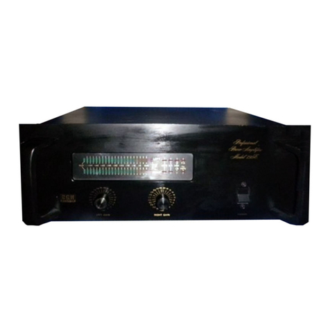
BGW 250C User manual

, .
OV/t·'
ERS
r·1AilUft.L
r10DEL
250C
STEREO
POHER
AMP
LI
FI
ER
t _
I -
I -
I •
I

I _
-IMPORTP.NT-
PLEASE
READ
THIS
PAGE
BEFORE
OPERATING
YOUR
BGW
POweR
~~PLIF!ER
Your
ne~.;
EGW
pc<..;er
amplifier
is
designed
to
provide
years
cf
trouble
free
performance.
Observing
these
few
precautions
will
insure
proper
operation.
Never
connec~
the
output
of
cne
channel
with
that
of
another.
Never
connect
a
direct
shcrt
from
the
output
cf
any
channel
to
ground.
Connect
~he~ower
card
~o
the
proper
voltage
~a~ns
(normally
-:::ls
-;.;ill
be
105-120
'/olts
AC,
50-60Hz).
Do
not
remove
the
factory
le=.d
seal.
?JU.plifiers
'.-lill
not
~e
covered
under
warran~y
if
~he
seal
is
braken.
:~ere
are
NO
adjust~en~s
wi~h~n.
! .

\ .
TABLE
OF
CONTENTS
1.
DESCRIPTION
2.
SPECIFICATIONS
4.
FACTORY
SERVICE
5.
INSTALU.TION
A.
Unpacking
B.
Mounting
C.
Output
Connections
D.
Input
Connecticns
E.
AC
Mains
and
Conversion
to
240
volts
6.
OPER.4.TION
7 •
SCEE!-'.P.T!C
D!AGRP-!'1
·1
8.
PARTS
LIST
10.
SERVICE
AU7HCRIZA'!!ON
FORM

1.
DESCRIPTION
The
BGH
Model
250C
is
one
of
the
most
advanced
dual
solid
state
power
amplifiers
available.
Unique
design
features
incorporated
in
the
Model
250C
make
it
virtually
"FAIL
SAFE"
and
free
from
accidental
damage
caused
by
human
error
in
audio
service.
A
fast
acting
relay
circuit
is
employed
as
a
safeguard
for
your·speakers.
The
circuitry
controlling
the
relay
constantly
monitors
the
individual
outputs
of
each
channel.
~_en
any
positive
or
negative
DC
component
of
more
than
+10
volts
occurs
at
the
output,
the
circuit
activates
the
relay
which
disconnects
the
speakers
from
the
amplifier.
The
speed
at
which
the
relay
responds
is
approximately
20
milliseconds
(see
figure
1).
The
relay
circuit
also
supplies
a
tL~e
delayed
cennection
of
~he
spe~~ers
to
the
amplifier
to
eliminate
unwanted
noises
at
turn
on.
On
the
front
panel,
the
en-off
switch,
gain
controls,
and
the
L.E.D.
pilot
lamp
and
clipping
indicators
are
mounted
for
ready
use.
Tne
packagL!g
inside
your
250C
is
lli!like
ordi~ary
power
amplifiers.
Each
ch~!nel
assembly
is
on
its
ewn
separate
module,
which
simply
plugs
in
or
out
fer
quick
and
easy
service.
Each
of
these
units
is
constructed
on
a
large
aluminlli~
extrusion.
The
~otal
radia~i~g
surface
area
of
each
heat
sink
is
330
square
inches.
The
heat
sinks
~ave
mating
circuit
boards
which
carry
the
passive
components.
Each
unit's
wiring
is
identical
with
the
next
as
the
circuits
are
pho~o
etched.
The
heat
sinks
plug
in
with
~~
8-pin.
cennector.
The
O'..ltput
stage
of
your
al!lplifier
uses
the
!:lost
advanced
tj""?e
ef
transistors
available.
~ese
large
geometry
power
devices
have
large
safe
eperating
area
aleng
base
with
extehded
power
bandwid~h.
All
the
semiconduc~ors
in
the
output
stage
are
in
int;~ate
contac~
wit~
the
hea~
sink.
~~e
bias
circui~
is
also
~ounted
on
~his
::'so~::-:'erm
"Nh~cn
provides
rock
steady
bias
stability
\vic:h
tem~era~~e.
The
voltage
gain
circuits
are
alse
lllounted
on
the
sa...'Ile
circuit
card.
A
true
operatienal
a...'Ilplifier
integrated
circuic:,
her-
metically
sealed
in
a
metal
can,
ac~s
as
the
front
end.
T~e
op
amp
(as
they
are
called)
is
a
special
anit
featuring
high
speed
as
iP...z)
and
a
high
sle''''
rate
(50
volts/!:licresecond)
yet
still
having
very
10f..,
noise
due
to
i
ts
darli~gton
input
stage
and
careful
design.
The
op
amp
stage
is
followed
by
a
discrete
cemplementary
~a~r
acting
as
active
current
sO'..lrce/sink
and
provid~g
additienal
voltage
gain.
!he
current
scurce
is
the
ideal
way
te
drive
Gl.e
OU~pU1:
s~age
whic!1
is
basically
a
'lol"tage
fellower.
-
~
.

This
sophisticated
circuit
design
makes
for
an
extremely
accurate
amplifier.
The
open
loop
gain
is
higher
than
found
in
the
competitors
T
products..
The
accuracy
of
an
amplifier
is
a
function
of
the
ratio
of
the
open
loop
gain
to
the
closed
loop
gain.
In
this
case,
the
open
loop
gain
is
about
1,000,000.
This
extremely
accurate
signal
processing
enables
the
Model
250C
to
drive
speakers
at
very
high
levels
while
adding
absolutely
no
coloration
of
its
own.
Even
at
mill
hIatt
levels
the
output
waveform
exhiBits
no
sign
of
crossover
distortion.
The
dynamic
range
capability
of
a
typical
250C
is
almost
1~5dB.
2 •

~
-
I r
--
---
-
-
-
- -----
1
second
nmnlTI1TOTrrnmlrrrrllllllili
rrnr
nl
SPEAKER
PROTECTION
TIME
D.C.
VOLTAGE
ON
SPEAKER
TERMINAL
075
ms
VS.
SIIUT
DOWN
TIME.
750
filS
625
rns
500
IRS
w
375
ms
250
ros
125
inS
-
o
10
-V
20
V 30V
40
V
50
V
50
V
70
V 00 V
D.
C.
VOLTAGE
Figure
1

2. SPECIFICATIONS
The
followi:lg
specifications
are
guaranteed
minimum perfc::'r.1ance
levels,
:lot
typical
or
ces't
case
mllnbe~s
measured
ti.'"1de:,
c.esired.
conditions.
All
'test
procedures
used
are
accorc.ing
to
t~e
most
conservative
tec~iques
i:l
use
~oday.
STEREO
MODE
-8
OEP.S
POWER
OUTPUT:
100 'i;"atts
average
continuous
pCrder
per
cha::nel
TOTAL
F..ARMONIC
DISTORTION:
Less
th~'"1
0.1% f:'om
.25-105
watts
~er
cha:lnel
POI-iZR
BAND:
c.at
rated
porHer 1
2a
~z
-20
k..:':..z
DTPw'"T
SENSITIVI'r!:
Approx~:nately
1.
5
volts
requ:"red
for
':'..l1l
ou'tp,~t
DA.l."!?ING
?ACTOR:
Greater
tha...'"1
500
at
low
freq'J.erl.cies
S:'EREO
~'!ODE
-4
O~S
pctVER
OUTPUT:
126
watts
average
ccnt
....
:"1'..lOUS
povTe.!"
per
clia.:,
....
"le.l
TC:'.:l.L
::".!3..:.'10NIC
:ISTC~T!mr:
..
...
~c.
_~
--~-
~ess
~~an
0.15%
frc~
.2S-1S~
?Oiti::?
=J..l~J:
2a E= - 2
'J
kEz
GA::-r
:
2Sd.3
l20x)
OU:'?TJT
:21P'E:JP1~C::::
Desi~ed.
for
any
load
~pedance
greater
t~n
~
c~s
?mfE:?
CU7?TJ7:
: 3J
",.;a~-:s
a'le~:.g==
c'.J~"':::"'-.."...,;.cu.s
?O~'ie~
:'G:
..
~
..
L
::..~_.rt~C'~IC
J:S::,2.::C~r:
:'ass
-::--:a.:l
.l%
:~o~
.2=-23G
"NC:~--:S
-:e=,
c!:..=.l"'J.:1e:
?C~'iE?~
2•
.!J~D:
2JE= - 2
G::E=
-
I,
.

INPUT
SENSI:IV!T~:
App~oxima~;11
.75
volts
~eaui~ed
for
full
ou~put
~ONO
r!ODE
- 8
OF.HS
PO
\VE..~
0
U:PUT
:
251
wa~~s
ave~age
continuous
power
TOTAL
F~Jl~ON!C
D!STOR!ION:
Less
than
.15%
from
.25-360
wa~~s
pe~
char~el
POWER
BAND:
20
Hz
-
20
kSz
INPUT
SENSITIV!TY:
Approx~a~ely
.SO
volts
~ecui=ed
for
full
ou~u~
GAIN:
320.9 (4.0x)
OUTPUT
r:!pED.A1'rc~:
De5~gned
for
ar.y
load
~~eca~oe
~eat;~
tha~
4.
o~s
F~EQ1J~rC~
RES?ONSE:
+0,
-.2Sd3
20Hz
~o
20kP.z
+0,
-3d3
2~z
to
5S~qz
!:-!
DISTCRTION:
(SO
anc
i
k~z
~:l)
:".:55
t::'a.'"'l .02%
at
~a-:;c. ?O'ile~
I:,I?Tj:'
:!::1:::~P.1TCE:
w.
7 , 000 0
r-.ms
?~IS:::
7::~~:
.: :n:'c=::sacc:!c.s
;:,_7;:,:
~.1r~
:ro
:SE
(2
GE= - :
JkEz
)
:J5
d3
~elow
ratec
pcwe~
?C~'lZ~
?,EQUI~:2:'!E:~':':
,:-
..
1']5-120
volts
50-60::.=
-'-
'10:'
-:5
~:~!
r
c~r:
!~~e
~e:ay ~~lay
~~~~
C~,
will
a?pear
a-
cu~;ut.

I •
I .
OUTPUT
PROTECTION:
Each
channel
is
protected
against
shorts,
open
circuit
operation,
mismatched
loads,
etc.
LOAD
PROTECTION:
A
unique
relay
circuit
protects
speakers
against
malfunction.
OVERALL
PROTECTION:
Power
line
is
protected
'IIi
th
fast
acting
circuit
breaker.
ilo
fuses
of
any
kind
are
used.
Two
thermal
switches
(one
per
channel)
protect
against
over
temperature
operation.
Controlled
power
bandwidth
and
slew
rate
protect
tweeters
and
~~plifier
against
excessive
high
frequency
operation.
Input
overload
protection
is
afforded
op
amp
by
series
limiting
resistance.
POWE~
SUPPLY:
A
large
power
transfor~er
with
t~in
primary
windings
is
~sed.
Computer
grade
electrolytic
capacitors
storing
over
22
joules
of
energy,
and
a
25
amp
bridge
rectifier
are
employed.
Two
zener
regulated
supplies
power
each
operational
amplifier
front
end.
POf../ER
REQUIRElSN'r'S:
Unit
reauires
either
l05-l20V
AC
er
2l0-2~OV
50-60Hz
power.
A 5
amp
-circuit
breaker
is
supp
lied
fer
units
'.-lired
for
120?
operation
or
a
2.5
amp
brea~er
for
2~OV
cpera~ion.
HEAT
SINKnrG:
Each
channel
has
i
ts
o~vr.
removable
heat
sink.
Each
extrusion
has
330
square
inches
of
surface
area.
CE..A..SSIS:
A
heavy
steel
c~assis
forms
a
prot:ective
cage
for
u~~atc~ed
mechanit;al
streng:t!1.
A
3/15"
al'..x.i--lI.l.ffi
r":.ck
mount
panel
is
suoolied.
All
modules
are
bolted
to
the
cr.assis.
The
pewer
s~pply
is
set
close
to
the
front
~a~el
to
allew
racx
mount:i~g
p';
;-hou
....
:.....~e
__
"se
'-
ot:
~
____
.j
~
or
.:::··.,..~o
.....
t-
ue
'"'u':,.4."
'l"'a';
~
-l,..Ir.r:-
~"'f_'-
I".
••
.J.
__
J.
CONNECTCRS:
Out?ut:
Standard
3/~1t
spaci:1g,
;:
~
..
ay
bindi::g
pos~s
fer
ou~puts
(color
coded
for
easy
identi~icaticn).
l:nDut:
l/~"
phone
jack,
3
pin
female
audio
connector.
AC'Line:
Three
wire
grounded
~ail
connector
on
fi~e
foot
. . ,
In1.n. caD
...
e.
~ODULZS
:
,!,:"ree
plllg-in
:nodules
contain
95%
of
the
ci.rcui
t.ry.
:lodules
ccnsis~
of
two
hea~
sink
channel
assemblies
and
o~e
relav
circ'..li~
board.
CIRCUIT 30ARCS:
F:2l-:le
retardant
glass
epoxy
beards
:)er
ill':".:..
s~ec.
6 •

DI1'!ENSIONS:
Panel
19"
IV
x
5~"
H x
11-3/4"
D -
black
annodized-grained
alumi:lum.
The
notchi:lg
is
standard
E.!.A./Western
Elect~ic.
fNEIGHT:
27
pounds
net
weight.
35
pounds
packaged
weight.
Shipping
container:
a
unique
double
boxed
system
providing
maximum
safety
for
the
unit.
7.

3.
f..JARRAN
TY
BGW
Systems
warr~!ts
all
power
amplifiers
for
a
period
of
three
years
from
date
of
manufacture.
This
warranty
covers
both
defects
in
workmanship
and/or
materials.
If
malfunction
does
occur,
the
product
will
be
repaired
or
replaced
(at
our
option)
without
charge
for
materials
or
labor,
if
returned
prepaid
to
BGW.
The
warranty
does
not
cover
equipment
damaged
due
to
negligence,
misuse,
shipping
damage
or
accident,
or
if
the
serial
number
is
defaced,
altered
or
removed.
Further-
more,
units
that
are
altered,
modified
or
improperly
serviced,
in
any
instance,
will
not
be
repaired
u~der
terms
of
warranty.
4.
FACTORY
SERVICE
Should
service
be
required,
please
fill
out
the
Service
Authorization
Fo~
and
mail
~~
to
BGW
Systems.
All
units
must
be
shipped
prepaid
in
the
factory
supplied
sn~pping
container,
in
order
to
prevent
damage
in
transit.
Units
will
be
returned
by
freight
collect.
S.
INSTALLATION
UNPACKING:
iI _
Your
BGW
~ower
amolifier
is
shiooed
in
an
advanced
double
boxed
.
.-
.
..
~..
container:
The
container
should·be
saved
~n
even~
~ne
un~~
is
moved
or
shipped
at
some
future
date.
Replacement
containers
are
available
from
BGW
Systems.
I
I •
Inspect
the
unit
for
damage
ih
transit
i~~ediately
upon
receipt.
If
damage
is
found,
notify
the
transportation
company
~ediately.
On2..y
the
consignee
may
institute
a
claim
'..;i
th
the
carrier
for
shipping
damage.
SGW
will
cooperate
fully
in
such
e'/ent.
Be
=ure
~o
save
the
container
as
evicence
of
dawage
for
the
shi?per
to
i~spect.
~CUNT::NG:
T:'1E
BGhT
::lON'er
a':!.o
is
supplied
"lith
a
heavy
sta..'1ciard
19"
rac!<
?~,e:.
The
~'1it-may
be
bolted
into
a
rack
by
the
front
panel
as
long
as
provisions
fer
~res~ricted
air
flew
are
provided.
Good
7entilation
practice
wi.ll
provi~e
for
air
flow
above
and.
bele~
~he
unit.
I~adequate
ventilation
may
cause
the
protective
thermal
s"tli
tcne
s t
':
J
shut
-:he
unit
eff.
Nor~al
Installation:
All
connections
should
be
made
before
iJCT..;er
is
aDo
lied"
The
250C
is
desi~ed
to
operate
in
e~~her
the
Stereo-(2-channel)
mode
or
Monaural
(bridged)
mode.
A
slide
switch
loca-:ed
Ch
the
rear
of
the
unit
swi~ches
from
one
~ode
to
the
other.
Select
the
~ode
required,
then
follcw
~he
directions
~elcw.
8 •

INPUT
CONNEC~IONS
-
STEREO
MODE
Shielded
OU~?ut
cables
from
the
preamplifier
should
be
connected
to
~he
two
input
jacks
on
the
amplifier.
On
the
Model
250C
the
input
jacks
requ~re
standard
1/4"
diameter
phone
plugs;
(~he
input
lL~es
should
be
unbalanced)
or
three-pin,
male
audio
connec~ors
(such
as
the
Cannon
XL
Series,
or
Switchcraft
A3
Series).
To
use
the
Model
250C
with
high
impedance,
unbalanced
input
lines,
use
the
jumper
plug
provided
in
the
transformer
socket
and
connect
the
input
cables
as
follows:
(f)
2
MODEL
SIGNAL o 0 25CC
3
SOURCE
HI
o---v
o
DrpU~
INPUT
CABLE
/I""
NO~E:
SHIELD
NOT
CONNECTED
TO
.A.}rfTEDTG
no
...
SIGNAL
SOURCE.
To
use
tha
Model
2SaC
with
balanced
input
l~~es,
remove
. l
the
j~per
plugs
frem
the
transformer
sockets
and
replace
them
with
tr~~s=ormers
of
~he
desired
Lnoecance.
C~nnect
the
~~put
cables
as
follows:
-
~--~
:~CJE::"
SIGNAL
1
o a
O~C
2SaC
SOURCE
3
(!j)
fl)
z
,"''CTT''!'
C __
*_
..J_
"'"
\..J
Inout
connec~ions
should
be
as
short
and
direct
as
oossible.
Shielded
cables
~ust
be
used
and
beth
should
originate
fro~
the
same
source
(i.e.,
if
both
ch~~els
de
net
come
same
pre~ps,
ground
loep
problems
may
arise).
~e
sou=ce
must
be
capable
of
delivering
1.25
velts
full
output
from
the
amplifier.
frem
for
~ne
9 •

For
maximum
signal
to
noise
ratio
driving
source
impedance
should
be
less
than
5,000
ohms.
Radio
frequency
interference
(RFI),
when
it
occurs,
can
be
reduced
or
eliminated
by
employing
one
of
the
filters
shown
below.
They
should
be
built
in
shielded
enclosures
such
as
3Smm.
aluminum
film
cans.
1.8
K
Al
A!)
600
CF...l.'1
....
V'v¥l
SOURCE
.003uF
-r
6dB/octave
rolloff
above
~
20kHz.
SmH(JH
Miller
6304-)
l2dB/cctave
rolloff
above
____
~COO-~~,~
__-
20kHz
At'!P
6000HM 1
SOURCE
.018uF
--r
8
INFU7
CONNECTIONS
BRIDGE
MODE:
?o:low
~he
same
procedure
as
outlined
for
Stereo
~
·
~cde
but
use
only
one
shielded
cable
plugged
into
channell.
I::o
:101:
connect
any~hing
to
the
input
of
channel
2.
OUTPUT
CONNEC7IONS
STEREO
MODE:
Connect
the
left
speaker
to
the
binding
posts
marked
CH
1
~~d
the
right
speakers
to
the
bindL~g
posts
marked
CH
2.
Observe
the
phasing
of
the
spe.:>~,<ers.
Most
cor-nectars
on
spea~<er
cabinets
are
either
color
coded
or
marked
+,
-.
Connect
t~e
black
or
~inus
(-)
te~inal
0:1
the
5~e.:>ker
cabinet
~o
the
black
~inding
posts
on
the
~uplifier:
Connect
~he
ether
speaker
term;~al
to
the
red
binding
post.
lQ.

The
wires
used
for
the
sneaker
leads
should
be
of
the
largest
gauge
possible
in
order
to
retai~
the
highest
damping
factor
possible.
The
chart
provided
shows
the
relation
between
wire
size
and
damping
factor.
To
find
the
damping
fac~or
of
a
particular
configuration
of
wire
size
and
length
and
speaker
impedance,
take
a
ruler
and
line
up
the
length
of
two-conductor-cable
used
with
the
wire
gauge
used
and
mark
the
resulting
source
resistance.
Then
line
u~
this
value
with
the
resistance
of
the
load
and
read
off
the
resulting
damping
factor.
For
dy~amic
moving
coil
speakers,
the
load
resistance
should
be
that
measured
with
an
ohmmeter
across
the
speaker
terminals,
not
the
m~~ufacturer's
s~ated
L~pedance
value.
For
electro-
static
spe~~ers,
the
ma~ufacturer's
value
should
be
used.
ror
best
results,
choose
a
configuration
of
wire
size
and
length
that
will
result
i~
a
d~~ping
factor
of
50
or
greater.
Ideally,
the
output
leads
should
be
connected
to
the
amplifier
with
standard
ba~ana
plugs;
however,
the
five-way
action
of
the
bindi~g
posts
permits
the
use
of
t
inned
~.;ires
or
spade
lugs.
OuTPUT
CONNECTIONS
BR!DGE
XODE:
Follow
the
s~e
orocedure
as
outlined
for
Stereo
mcde
but
CO~Lec~
~he
singie
output
acrOS3
the
twc
red
binding
posts
of
Chan~els
1
and
2.
Do
not
connect
anything
to
the
Channell
or
Channel
2
ground
bi~dL~g
posts.
The
2S0C
is
furnished
with
a
three
~ire
cord
and
a
ground
plug.
Defeating
the
grounding
provision
may
create
hazardous
condi~ions.
:~e
amplifier
should
be
plugged
in
only
when
it
has
been
established
that
it
is
~ired
for
the
correct
oower
~a~~s
voltage
~d
after
all
ether
connections
to
~he
~;~li=ier
have
been
ma
·
::e.
The
mains
CAC
li::e)
voltage
is
indicated
on
t::'e
serial
nl.!.I:lber
label
on
~he
rear
of
the
amplifier.
~~plifiers
su?plied
for
use
in
the
United
States
are
fac~ory
wired
for
120
volts.
Only
the
i::dicated
~ains
voltage
should
be
used.
!f
the
mains
voltage
must
be
changed,
see
~he
next
page.
1.1.

CH&~GING
THE
MAINS
VOLTAGE:
The
mains
voltage
may
be
changed
in
the
field
by
following
procedure:
1.
Remove
the
amplifier
cover.
2.
Change
barrie
of
the
the
transformer
wire
r
strip
to
match
the
chart
below:
s
going
appropr
to
iate
the
mains
column
TOP
!.
l20V
24-0V
1
2
Yellow
Brown
Brown
3
Red
Yellow
Orange
4-
Orange
Blue
Blue
5
Red
,.
0
Green
Green
3.
Change
~he
circuit
breaker
on
~he
fron~
?~~e:
as
=ollows:
ror
100
and
120
velt
operation,
use
S
amo.
For
24-0
volt
operation,
use
3
amp.
Replacement
breakers
are
available
from
BGlv
Systems
for
$10.
ao
each
,
postpaid.
Include
the
serial
:-.umber·
and
model
of
yeu:::,
ur.i~
r..;hen
yeu
order.
12.

---
-
,
~ a,
LCAO
scuaa
11SI5T.AHa
II5JSTAHa
~
1
I"
..,
~
·1
·
j
f·
,....---4.
=-••
::
~.
-~
I
::.
1-
~-..
-
.
.....
1.
2
E'CAL\fPLE:
It.
80
RS
2 .0411
OR
D.
F.
:a
ZOO
l.. '
CABLE LENGTH.OF
20
FT.
..lJfSi'lER: #:10 WIRE
FI~JRE
Z
SOURCE
~SIST_.\J.\lCE
A1ID
DAl·tPING
FACTOR
VS.
L:2:-TG7H
.:lJ.\ffi
sr:::=
OF
OUTPUT
LEADS
I _

6.
OPERATION
TURN
ON:
The
Model
250C
is
free
from
thumps
Or
transients
during
turn
on.
Often,
turn-on
transients
originate
in
the
preamp
or
t~~er.
This
is
especially
true
of
tube-type
units.
If
this
situation
arises,
turn
the
amplifier
on
after
the
other
units
have
had
sufficient
tL~e
to
stabilize.
PROTECTION:
Three
protection
circuits
are
employed
in
the
Model
250C.
1.
The
fast
acting
magnetic
circuit
breaker
shuts
-
the
unit
down
whenever
the
unit
draws
excessive
current.
2.
The
fast
acting
relay
circuit
i~stantaneously
disconnects
the
amp
outputs
from
the
spea~ers
if
any
condition
exists
that
will
damage
the
speakers.
3.
Thermal
switc~es
mounted
on
each
heat
sink
protect
the
amolifier
from
thermal
failure.
The
amolifier
will
shut
off
if
the
heat
sink
temperature
rises
above
85
degrees
Centigrade
a~d
will
~urn
on
again
when
the
temperature
drops.
Activatio~
of
the
thermal
switches
usually
means
that
insufficient
air
circulatio~
is
being
allowed.
13.

....J
-'
PARTS
LIS'f
R£fEt{CNCE PA1n' REfERENCC
PART
NO. NO.
DESCHIPTJON Q'rY.
NO. NO.
DESCRIPTION
Q'rY.
llEATSINlC
MODULE
IU~SIS'rORS
SEtlICONDUcrfORS
R20-33
II
050- 0330R
.330hm
5W
6
Q1
185
1
1-0410
110
1
110 1
R3
1
1
11025-2070
2.7ohm
2W
1
Q2
1854-0
1109
40409
1
R25,26,27
II
025
-1
{)
01 100hrn
2W
5%
3
Q5
185
1
1-6211
2N6211
1
1<35
11050-
300
1 300lllfi
5W
1
QII
1854-3583
2N3585 1
R23
,211
5005-6800
G80hm
!iW
2
Q3
1853-3053
40309
1
R22,10
5005-1002
100o\1lfi
!;,iW
2
Q6-11
185
1
1-0636
MJ15015
6
In6
,19,20
5005-6001
6800hrn
!;lW
3
Q12
5401
1
R2,6,9,13
5005-1003
1K
~W
II
CR1,2
1900-4740
1NI17
II
OA
2
R8)
II
5005-1502
1.5
K
!2W
2
CR3,
II)
6-9
1900-
1
1004
1N4004
2
H5
5001-2
1
191 2,
II
9}(
!;M
1% 1 1C1
1885-0318
LM31811
1
In,
RI12
5005-
1
1702 11.7K
!iW
2 Q12
1853-5401
2N5451 1
In
7)
18
5005-1503
15}(
!;M
2
Q1
1
1,13
185
11-00
113
MPSA13
2
R3)
15
,
II
0 , 36
5005
-11'/03
117
K
!2W
II
R7
,
II
.
5061-
1
1752 117.51(
!2W
1%
2
HARDWARE
R37
,38,
III
5005-1005
100
K
!2W
3
IU
5005-1006
1Meg.
!iW
1
0770-1312
Stand
off
II
)~39
5005
-1
00
II
10
K
!2H
1 B1532B
RI13
5005-3602
3.6
K
!2W
1
1231-1112
Lug Mo1ex 9
02-0
1
1-1
CAPACITORS
0723-33
1
17
.
Insulator
16
Shoulder
CII
,0
0100-00li7
117
pi'
2
CI3
0090-0120
120
pf
1
C2
0090-02110 21
10
pf
1
CII
I,16
0100-1000
1000
pf
2
C5,6
0129-00
1
17
.0
1
17
uf
25 V 2
CI5
0129-0100
.1
uf
25V
1
C17,18,19
0369-0100
.1
uf
100V 3
C1
0226-0010
10
uf
25V I
CI1,12
01
186-0010
10
uf
100V 2
C3
01
156-0050
50
uf
12V 1
C"I
0100-0068
68
pf
1kV 1
C20 0369-01170
,117
uf
100V 1
C10
0100-5000
5000
pf
lkV
1
14.


PAR'fS
LIST
HEITRE:NCE
PAR'!'
REFERENCE PAR'r
HO. HO.
DESCRIPTION
Q'l'Y. NO. NO.
DESCRIPTION
Q'fY.
PLUG 1 SOCKET, CONNECTORS
9999-2085
Feet
Rubber
4
200S
1231-3003
cnctr.Trn.
1
P1,2
1350-0000
Plug
0
pin
2 COMPLETED ASSEMBLY
J5,0
9999-0111
Jack
Input
2
J3,6
1231-0008
Red
Binding
2
1000-1260
Heatsink
Module
post
1100-1260
Harness
JII , 'I
1231-0009
Black
13inding
2
9017-1250
Crowbar
post
TD1
0720-9126
Bapr'le
r'
Strip
1 PACKING CONTAINER
J11,12
9999-0130
Jack
Input
D3F 2
,I9,10
1203-0008
Socket
0
pin
W/RI
2
9700-1260
Manual
1
9851-1250
Outer
Box
1
IIAIWWARE
9850-1250
Inner
Box
1
2605-()625
\-20x5/8
brsh.
II
9852-1250
Rail
Block
2
A1uIOinurn
985
1
1-0150
Corner
Block
8
0607-0125
~IDx120Dx.
12
II
LUGS
1313-3
1157
Lug
Crimp/llO
9
1322-9700
Lug
s1ipon
18
16-111
1321-5305
Lug
slipon
2
1231-1105
Lug
t--lo1ex 8
02-05-1
METAL
9002-1260
Chassis
250C
1
9000-1252
Front
Panel
1
9005-1260
Cover
1
MISCE:J.I.ANEOUS
P2
0706-0103
Line
Cord
1
S3
0611-0191
Switch
dput.
1
9999-0019
Tie
Wrap
25
1235-0001
Clamp
Cap.
2
1235-60311
C1dmp
Strain
He1 1
CDl
0650-0602
SvJi
tch
Rocker
1
0'/21-0312
Darrier
fish
1
paper
16.
Table of contents
Other BGW Amplifier manuals
Popular Amplifier manuals by other brands
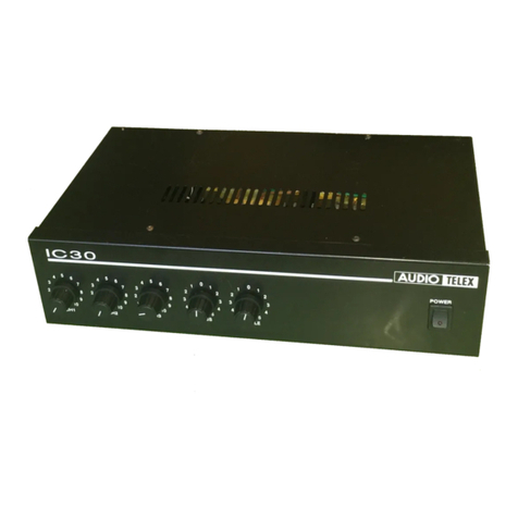
AUDIO TELEX
AUDIO TELEX IC30 Brochure & specs
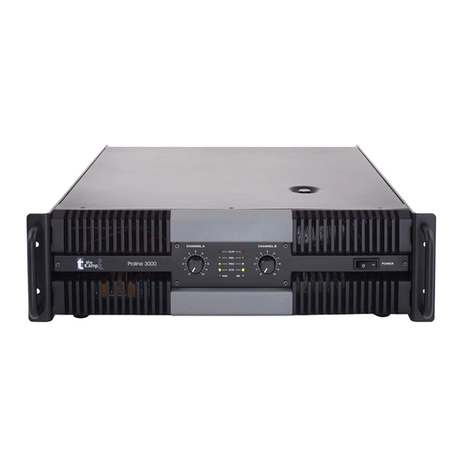
t.amp
t.amp Proline 3000 user manual
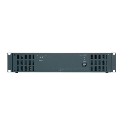
AUSTRALIAN MONITOR
AUSTRALIAN MONITOR AMIS480P Installation and operation manual
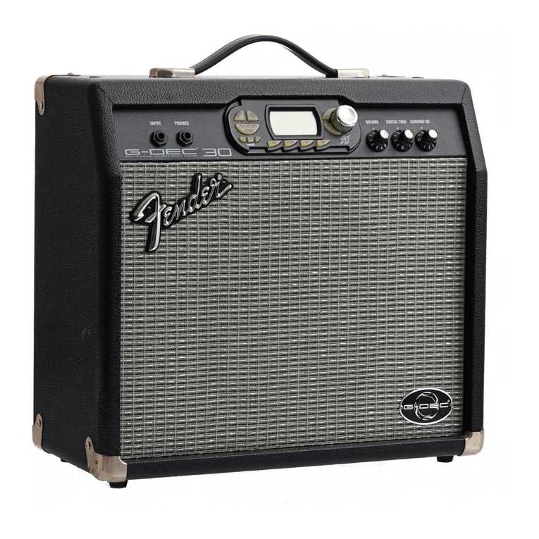
Fender
Fender G-DEC owner's manual
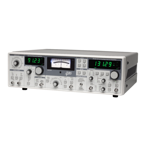
Stanford Research Systems
Stanford Research Systems SR124 Operation and service manual

Zesto Audio
Zesto Audio Andros PS-1 owner's manual


