BGW 8000 User manual

.. ,
I
~
!1
liv
STEMS
-J
U/
_ -
j,
.
13"1:10
SOUTM
YUKON
AVENue
MAWTMORNe.
CAL.'''OFINIA
902~O
PMONI!
(213)
e73.aoeo
TELEX
NO.
ee-44e~
.
.
MODEL
8000 TOROID
Proline U
OWNER'S MANUAL
DESCRIPTION
Important
••
. . . . . . . . .
Description
.
Product
Option • . .. •
I.
• • • . • •
J
Specifications • • •
I·
Unpacking
&:
Set-Up.
• . . . . . . . . . .
Rack
Mounting Hints
Input
Connections.
• •
Output
Connections •
Damping
Factor
Nomograph
Speaker Fuse Nomograph.
Mono
Operation.
• • • •
Power Mains
Connection.
•
Power Mains Voltage Conversion
Operation • • • • • • •
Circuit Description •
Service Instructions •
L'
.
;
I'
FORM NUMBER
00601
· . •
• 00843
00845
02303
• • • 02530
02660
• • • 02711
03431
•
••
03.510
• • • 03530
• • • 03691
• • • 04000
04132
05202
06283
13600

00711-2
Schematic
Amplifier
Module..
• • · . .. . . .. . . . . . . . • •
13620
Transformer
Schematics
Toroids
.. .. . .
1361.5
Heatsink Assembly Component
Layout.
.. . ·. . . . . . . . ...
136.50
Chassis
Schematic.
• • • • • • • . .. . . . . . . . . .
13611
Block Diagram
••••••••
·. .
...
13630
Display
Schematic
·. · . . . .. . .
13640
Parts
List • • • • • • • . . . .. . ..
13690
Warranty .. . .. ..
17000
Service Authorization Form ...
17020
Warranty
Registratjon
Form • · .. . . .. . . ...
17030
-

50023
!-
SYSTEMS
13130
SOUTH
YUKON
AVe:NUE
HAWTHORNE
.
CALIFORNIA
90250
PHONE
(213)
973-8090
TEL-EX
NO
.
66-4494
MODEL 8000 TEST
REPORT
TECHNICIAN:-;j
c1.J.J
SERIAL NO.: 0fi'IJ
13
53
LINE VOLTAGE: 12-0V
Power
@
Clip
(0.1%
THO)
8
ohms
-Volts
out
Power
Power
@
Clip
(0.1596 THO)
4
ohms
-Volts
out
Power
THD 200
Watts
-8
ohms
(40 Volts)
20Hz
20kHz
THD Mono - 8
ohms
650
Watts
(72.2 Volts)
1kHz
Small
Signal
Bandwidth
-3dB
Frequency
Noise
Level
Output
Noise
Voltage
20Hz
to
20kHz
Quiescent
Power
Watts
CH.
A
Lr7~
3\/
Ci'1q4--
.o~
96
%
96
.,J
%
~
%
•
(l
J
kHz
kHz
mV. mV.
7/29/83

11 •
00601-1
-IMPORTANT -
PLEASE
READ
THIS
PAGE
BEFORE
OPERATING
YOUR
BGW
POWER
AMPLIFIER
Your new
BGW
amplifier
is designed to provide years of
trouble
free
performance.
Observing
these
few
precautions
will insure proper operation:
Read all Instructions
before
connecting any AC power
to
your power
amplifier.
Retain
this Manual for
future
reference.
Heed all warnings on
the
top
or
rear
of
the
power
amplifier.
The
amplifier
should
not
be used
near
water
-for
example,
near
a bathtub,
washbowl, kitchen sink, laundry
tub,
in a
wet
basement,
or
near
a swimming pool,
etc.
The
amplifier
should be
situated
so
that
its
location
or
position does not
interfere
with
its
proper
ventilation.
For example,
it
should not be
situated
on a bed,
sofa,
rug,
or
similar
surface
that
may block
the
ventilation openings;
or,
placed in a
built-in
installation,
such
as
a bookcase or
cabinet
that
may
impede
the
flow
of
air
through
the
ventilation
openings.
The
amplifier
should be
situated
away from
heat
sources such as
radiators,
heat
registers,
stoves,
or
other
appliances
that
produce
heat.
The
amplifier
should be
connected
to a power supply only of
the
type
described in
the
operating
instructions
or
as marked on
the
rear
panel.
Precautions
should be
taken
so
that
the
grounding
means
of
the
amplifier is not
defeated.
The power supply
cord
should be
routed
so
that
it
is
not likely
to
be walked on or
pinched by
items
placed upon
or
against
it,
paying
particular
attention
to cord
at
the
plug, convenience
receptacles,
and
the
point
where
they
exit
from
the
amplifier.
Care
should be
taken
so
that
objects
do
not fall into, and liquids
are
not spilled
into
the
amplifier
through openings.
I

00601-2
The
amplifier
should be
serviced
by qualified
service
personnel when:
The power supply cord or
the
plug has
been
damaged;
or
objects
have
fallen
into,
or
liquid has been spilled
into
the
amplifier;
or has been
exposed
to
rain;
or
does
not
appear
to
operate
normally or exhibits a
marked
change
in
performance;
or
has
been
dropped,
or
the
enclosure has
been
damaged.
All
connections
should be made
to
the
power
amplifier
with
the
power
OFF.
Speaker
fuses
should be used
to
alford
maximum
speaker
protection.
Never
connect
the
output
of
one
channel
to
that
of
another.
Connect
the.
power
cord
to
the
proper
voltage
mains
as
indicated
on
the
rear
of
the
amplifier.
Conversion
to
another
voltage
requires
internal
rewiring.
Do
not
remove
the
amplifier's
cover.
Amplifiers
may
not
be
covered
under
warranty
if
they
are
tampered
with.
There
are
NO
adjustments
within.
Potentially
lethal
voltages
exist
within
the
amplifier.
Refer
all
service
work
to
an
authorized
BGW
service
station.

1I~'
00843
DESCRIPTION
The
BGW
Model 8000 is one of
the
most
advanced solid
state,
quasi-
complementary,
bridgeable,
stereo
power amplifiers
available.
Features
of
the
Model 8000 include Toroid Power
Transformer,
Forced
Air Cooling,
Power Switch, CirOJit Breaker, Input Level Controls, Modular Construction,
Display
Meter
Assembly, Dual Looping
~
phone jack5, and
electronic
DC speaker
.
protection.
The
Front
Panel includes two Input Level Controls, Rocker AC Power Switch and
Dual Tri Color
LED
Dispaly. Green LED's
indicate
power ON, yellow LED's
indicate signal
presence
and
are
labeled modulation, and red LED's
serve
as
overload indicators.
The
Rear
Panel includes AC Input Cord, CirOJit
Breaker,
two
sets
of looping
~"
Phone
Jack
Input
Connectors,
Red and Black .5-way Binding Posts for
the
output
of
each
amplifier,
and a Mono/Stereo Switch
to
convert
amplifier
to
a fully bridged
Mono
amplifier.
Provisions
are
also available for an input accessory module. This cirOJit board
provides balanced
electronic
inputs, subsonic
filter
and
electronic
crossover. The
input module can
be
added
at
any
time
by
a qualified
electronic
technician.
Both
the
circuit
and chassis grounds
are
connected
together
internally.
Refer
to
MFRM
04132
for
information regarding ground
separation.
The Model 8000 can
be
used for a wide
variety
of
applications. However, please
note
the
following
precaution.
1)
Do
not use the
front
panel as
the
sole support for
the
amplifier.
Side
rails or
rack
shelves should
be
employed.
The
output
stages
of
your Model 8000 use
24
Ultracase
tm
devices,
the
most
advanced
type
of
transistors
available. These
large
geometry,
200
watt
power
devices
(total
4800
watts)
have
large
safe
operating
areas
and
extended
power i
bandwidth.
Electrostatic
and
other
highly
reactive
speaker
systems
present
no I
I
difficulties
for
the
Model 8000. I
I
I
j

0084.5
The Proline n audio power
amplifier
model 8000 is
available
from
the
factory
with
custom
options
to
fi
t your needs.
Some of
these
options may require a minimum
quantity
of
products
to
be
purchased
at
one
time.
Please
contact
the
factory
with
your
requirements.
Some
of
the
options
for
the
8000
are
listed
below:
8000-01
Active
Electronic
Balanced
Li.ne
Inputs
8000-02
Electronic
Crossover
8000-03
Transformer
Balanced
tine
Inputs
With
Looping
XLR's
8000-04
Unbalanced
Line
Inputs
With
Looping
XLR's
Rev.
7/12/84

02.303-1
THE
BGW
8000 TOROID
PROFESSIONAL POWER AMPLIFIER
Exacting design
standards
and unique
features
establish
the
BG
W
amplifier
as
the
industry
leader
in power amplifier techn<tlRgy.
Features
such as all
steel
welded
chassis and
covers,
exclusive
Ultracase
output
transistors,
totally
modular
construction,
massive aluminum heatsinks,
state
of
the
art
toroidal power
transformer
and low
feedback
discrete
circuit
design have
set
the
industry
standard
in audio power amplifi
ers.
Delivering a full
22.5
watts
per channel into 8 ohm loads and
capable
of
driving
loads
as
low
as
2 ohms. The Model 8000
offers
reliability
and
performance
unparalleled in
the
industry.
SPECIFICA
nONS:
BGW
MODEL 8000 TOROID
OUTPUT POWER
22.5
watts
minimum sine wave continuous
average
power
output
per
channel with
both
channels driving 8-ohm loads over a power band from 20Hz
to
20kHz. The
maximum Total Harmonic Distortion
at
any power level from 2.50-millwatts
to
200
watts
shall be no
more
than
.0.5%
from 20Hz
to
10kHz and rising
to
no
more
than
.10%
at
20kHz.
3.50
watts
minimum sine wave continuous
average
power
output
per channel with
both
channels driving 4-ohm loads
over
a power band from 40Hz
to
20kHz. The
maximum
Total
Harmonic Distortion
at
any power level from 2.50-milliwatts
to
3.50
watts
shall be no
more
than
.1.5%
from 40Hz
to
20kHz.
700
wa~
minimum sine wave continuous
average
power
output
monaural driving
an 8-ohm load
over
a power band from 40Hz
to
20kHz. The maximum Total
Harmonic
Distortion
at
any power level from 2.5O-millwatts
to
700
watts
shall be
no
more
than
.1.5%
from 40
to
20kHz.
*All
specifications
and
features
are
subject
to
change
without
notice.

02303-2
Intermodulation Distortion:
Small Signal
Frequency Response:
Hum and Noise Level:
Input Sensitivity:
Voltage Gain:
Input Impedance:
Damping
Factor:
Output
Impedance:
Power Requirement5:
Semiconductor
Complement:
Dimensions:
Weight:
SPECIFICATIONS
Less than 0.05% from 250 milliwatts
to
rated
output
power.
+0,
-3dB, 1Hz
to
100kHz,
+0,
-0.25dB, 20Hz,
to
20kHz.
Better
than
1l0dB
below 225
watts
into
8 ohms.
(A
weighted).
1.23 volts for
rated
power
output.
34.5
times.
15k
ohms.
Greater
than 200
to
1
at
8 ohms.
Designed for any load impedance
equal to or
greater
than
2 ohms.
120
volts A.C., 60Hz
at
14
amps Also
availab
le
for 100, 220
or
240 volts
A.C.,50Hz.
2 Ultra-low noise
matched
differential
pairs,
64
transistors,
32
diodes, 6 LED's,
2 Triacs, and 5 Zener diodes.
5 1/4" by 19"
standard
rack
front
panel.
Depth behind
front
panel:
5"
x
17
x 13.
(13.35 cm x 48.26 cm x 33.02 cm)
49~
Lbs., 22.50 kg shipping
43~
Lbs., 19.77 kg
net

02530
I'
I UNPACKING
AND
SET-UP
I Your
BGW
Power Amplifier is shipped
in
an advanced packing
container.
SA
VE
THE
CONTAINER
AND
ALL PACKING MATERIAL!
The
container
should be saved in
the
event
the
unit is moved or shipped
at
some
future
date.
Replacement
containers
are
available from
BGW
Systems•
.Inspect
the
unit for damage in
transit
immediately upon
receipt.
If
damage is
found, notify
the
transportation
company
immediately.
Only
the
consignee may
institute
a claim
with
the
carrier
for shipping damage.
BGW
will
cooperate
fully in
such an
event.
Be
sure
to
save
the
container
as evidence of
damage
for
the
shipper
to inspect.
The amplifier's mounting position must
be
chosen
carefully,
so
that
the
air
flow
to
the
front and
rear
of
the
unit is not
restricted.
Inadequate ventilation may
cause
failure of
the
amplifier.
For
rack mounting,
the
four rubber
feet
on
the
bottom
of
the unit may be removed and no hardware will be loosened inside
the
unit.
Do
not, however, use
the
front panel
as
the
sole support for
the
amplifier.
Side
rails or rack shelves should be employed.
DO
NOT
PLUG THE AMPLIFIER
IN
YET!
All connections should be made before power is applied.

02660
RACK MOUNTING HINTS
KEEPING
IT
COOL
A power
amplifier
draws energy
from
a primary
electrical
service,
usually a
120volts AC
outlet,
to
drive loudspeaker
systems
with an audio signal. Typically,
only
half
of
the
energy can
be
delivered
to
the
loudspeakers;
remaining
energy is
converted
into
heat,
and must be dissipated
(ventilated)
into
the
air.
Air
circulating
past
heat-producing components absorbs
the
heat
and
carries
it
away. To accomplish this, low and medium power
amplifiers
rely on natural
convection
currents,
while most high power
amplifiers
use
fans.
If
the
air
flow is
impeded,
the
resulting rise in
heat
may cause an
amplifier
to
stop
working or fail.
Circulating
air
currents
must
not
be
cut
off
when installing power amplifiers in
racks.
Power amplifiers using convection cooling
require
spacing between
amplifiers
to
permit
air
flow
between
them.
Power
amplifiers
using
forced-air
cooling, on
the
other
hand, can usually be
stacked
closer
to
each
other
and may
not
need.any blank panel spacing
between
amplifiers.
To
improve
natural
convection
currents
within a
rack,
a
chimney
can
be
created
by
closing
the
back of
the
rack and venting
the
rack
at
the
bottom
to
let
in fresh
air,
and
at
the
top
to
exhaust
hot
air.
Vents should
be
large
rectangular
slots
approximately
19"
wide
by
411
high.
The
rack
cabinet
will require some
type
of blower
if
a
large
air-flow
is required.
It
is
best
to
exhaust
air
from
the
top
of
the
rack
rather
than
to
blow
it
in from
the
bottom.
There will
t>e
less dust and
dirt
in
the
rack
this
way,
if
the
bottom
vent is
sufficiently
large.
INSTALLING THE UNITS
When racks
are
to
be
transported
or
used in mobile
installations,
some
means of
securing
the
rear
of
the
equipment is required. Angle
brackets
attached
either
to
the
bottom,
sides or
rear
panel
are
practical
approaches.

1 ,
\J.JI.I'8
a.
02711
STEREO INPUT CONNECTIONS
Dual looping
~"
in. phone jacks
are
provided on
the
rear
of
the
amplifier
for input
connections.
1/4 INCH PHONE JACKS
The 1/4" phone jacks
are
for unbalanced lines only (single
conductor,
shielded).
Simply
connect
the
shield
to
the
outer
sleeve
of
the
plug and
the
inner
conductor
to
the
tip,
or buy
ready-made
cables.
See
diagram below.
Connect
shield
here
~
~~f
...,.,r~~=====C:::=~::::~~/""'--~
Connect
inner
conductor
here
sleeve
tip
FOR
MONO
(BRIDGED) OPERA
nON
To
operate
the
unit as a Mono
amplifier,
use
the
Channel "A" input only. DO NOT
use
the
Channel "B"
input.
Remember
to
place
the
Stereo/Mono
switch
in
the
'I
Mono position.
Refer
to
Page
03691 for Mono
Operation.
!

03431
STEREO OUTPUT CONNECTIONS
MOdel
8000
Two
sets
of five-way binding posts, on
the
rear
panel,
serve
as
output
connectors,
with one black and one red binding post for
each
channel. Channel
IIA"
leads go
to
the
binding posts marked Channel "A"; Channel "B",
to
those
marked
Channel "B".
Output
leads
are
best
connected,
to
the
amplifier,
with
standard
banana plugs;
however,
the
five-way
action
of
the
binding posts
permits
the
use of tinned wires
or
spade
lugs.
Make
certain
that
the
speakers
are
properly phased.
Connect
the
black
or
minus (-)
terminal
on
the
speaker
cabinet
to
the
appropriate
black binding post on
the
amplifier.
Connect
the
red or plus (+)
terminal
to
the
red
binding post.
Check
to
see
that
the
Stereo-Mono switch on
the
rear
of
the
amplifier
is in
the
Stereo
position.
SPEAKER PROTECTION
The Model 8000 has DC load (speaker)
protection
built into
the
heat
sink module,
however,
all
speakers
can
be
damaged
by
having too much power appJied
to
them.
Fuse
protection
is an
effective
and inexpensive way
of
preventing
this from
occurring.
If
your
speaker
system does
not
contain
a fuse
or
a
circuit
breaker,
a
fuse should be placed in series with
each
speaker
and
the
wire going
to
the
red
terminal
on
the
rear
of
the
amplifier.
Maximum
protecti~
can
be
obtained
with
fast-acting
fuses. Use
the
value
recommended
by
the
manufacturer.
If
no
value is
specified,
use
the
chart
provided
to
select
the
correct
value. See page 03530.
To use
the
chart,
take
a
straightedge,
such
as
a
ruler,
and line
up
the
speaker's
impedance
with
its
peak
music power
rating.
The proper fuse value
can
then
be
read
from
the
center
column. Choose a
fuse
that
is
closest
to,
and below,
the
value
indicated.
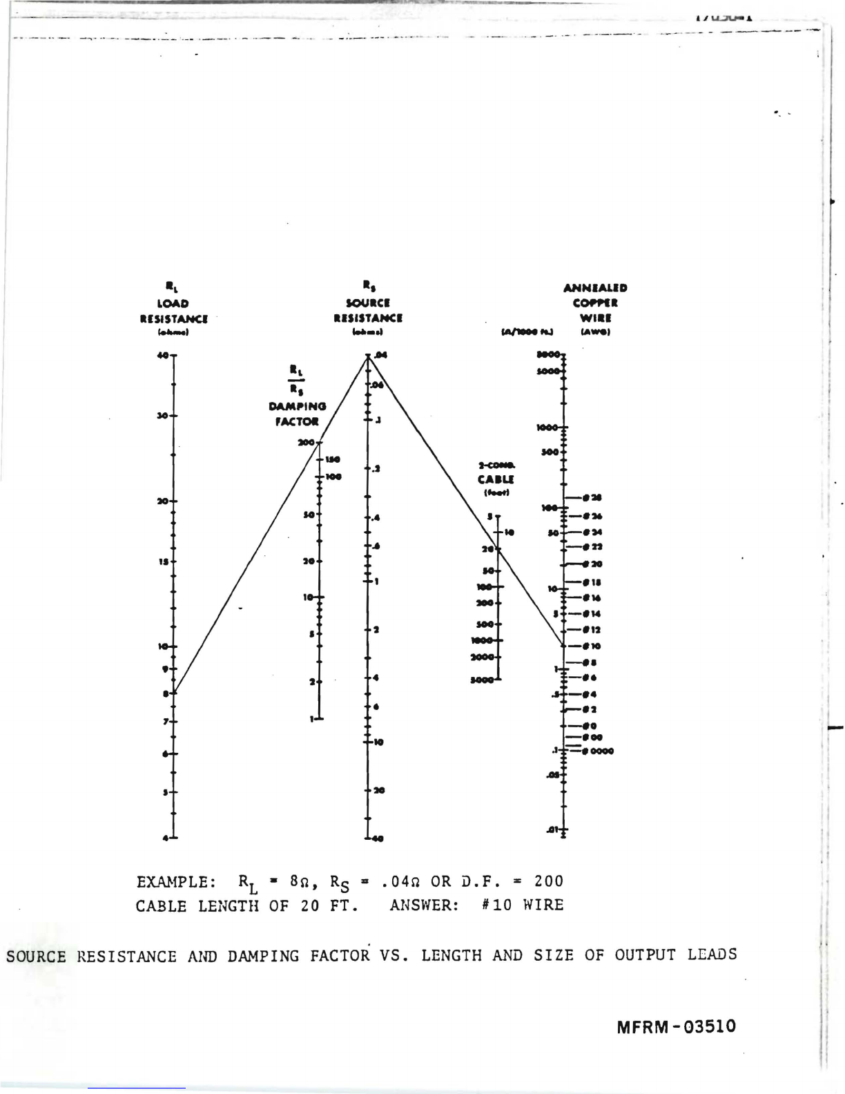
WIRE
SIZE
AND
DAMPING FACTOR
The high damping
factor
of
BGW
amplifiers
results in very
clean
bass response.
Excessively long, or small
diameter
speaker
wires
can
lower
the
damping
factor
and
distort
low frequencies. A damping
factor
of
at
least
50
should
be
maintained
to
insure good audio quali
ty.
The
relationship
between wire Jength and
diameter,
and damping
factor
can
be
calculated
using
the
chart
(MFRM-03510) on
the
foHowing page.
Proceed
as
follows:
1.
USing a
straight-edge,
line up
the
gauge
of
the
speaker
wire with
its
length.
Mark
off
the
resulting source
resistance
where
this line
crosses
the
center
column.
2. Line
up
the
source
resistance,
determined
in
step
1/
l,
with
the
manufacturer's
impedance of
the
speaker
system.
The damping
factor
can
now
be
read.
--
~--
. _.
..-
,,
_ . -
_.
_._
.-
-- -
..
- - -._- - -- -
--
0 • •
-,
AHNIALID
IOUICI
COPPCI
RlSfSTAHCI . IISISTAHCI
WII'
ret-e,
1M
...
IA
..
,
I'
J
•
10
.4
..
H
•
4
•
EXMfPLE:
RL •
SO.
RS
...
0412
OR
D.F
...
200
CABLE
LENGTH
OF
20
FT.
ANSWER:
#10
WIRE
SOURCE
RESISTANCE
AIID
DAMPING
FACTOR
VS.
LENGTH
AND
SIZE
OF
OUTPUT
LEADS
MFRM
-03510

."--.--0....-
_ _
__
_ _
4
5
•
7
1 •
10
12
14
16
20
2S
SPEAKER 1
,
.......
)
EXAMPLE:
~
-
8n,
PEAK
POWER
FUSE
SELECTOR
NOMOGRAPH
5
4
.2
J5
.1
.oa
FUSE
(
.....
,
400
300
200
150
100
10
60
40
30
20
PEAK
15
MUSIC
10 POWER
1
(watta)
•
4
3
2
1
SPEAKER
= 150W.
ANSWER:
FUSE
,.
2
AHPS
FOR
LOUDSPEAKER
PROTECTION
MFRM
-03530

·
~
...
03691
MONO
OPERA
nON
The
output
power
of
the
amplifier
can be increased
by
operating
it
in
the
Mono
(bridged) mode. The
correct
procedure for Mono
operation
is as follows:
1.
Set
Stereo/Mono
switch
to
Mono
position.
2. Use channel "A"
input
only. DO
NOT
use
the
channel "B" input.
3.
Connect
the
output
across
the two Plus (+) Terminals.
DO
NOT use
the
Minus
(-)
Terminals.
DO
NOT
reference
the load (speaker)
to
ground.
Designate
channel
"Art
as
Plus (+) and channel "B" as minus (-). Fuses, when
necessary,
should be
placed in
series
with one of
the
Plus .(+) Terminals.
"B" Channel "A" Channel
Input
.
Output
O©8
OCOCV
©@J
©~
mJ~
Output
Input
MONO STEREO
NOTE: Minimum load
impedance
for
Mono
operation
should be 8 ohms;
CIRCUIT DESCRIPTION
In
the
Mono mode,
the
output
of channel
"Art
is
fed
into
the
inverting
input
of
channel"B". The two channels work opposite
each
other;
when one goes positive,
the
other
goes
negative,
thus doubling
the
output
voltage
swing. The single
output
is
referenced
between
the
two red binding posts.

04000
POWER MAINS CONNECTIONS
The
unit
should
be
plugged in only when
it
has
been
established
that
it
is wired
for
the
correct
power mains
voltage
and
after
all
other
connections
have
been
made.
The mains (AC line)
voltage
is
indicated
on
the
serial
number
label
on
the
rear
of
the
unit.
Products
supplied
for
use in
the
United
States
and
Canada
are
factory
wired for 120
volts.
Only
the
indicated
mains
voltage
should
be
used.
If
the
mains
voltage
must
be changed,
see
POWER MAINS VOLTAGE CONVERSION.
A molded,
parallel
blade,
U-ground plug is
supplied.
This
connector
is
standard
in
the
United
States
and
Canada.
For use
elsewhere,
the
plug
must
be
replaced
with
the
correct
connector.
The
color-code
of
the
cord
is
as
follows:
HI
(switched Le$) -Brown (or Black)
LO
(neutral
Leg) -Blue (or White)
EARTH (Chassis ground) -
Green
with Yellow
tracer
(or
Green)

04132
POWER
MAINS
VOLTAGE CONVERSION
CAUTION: These servicing instructions
are
for use
by
qualtiied personnel only.
To
avoid
electric
shock,
do
not
perform any servicing
other
than
that
contained in
the
Operating Instructions, unless you
are
qualtiied
to
do so.
Refer
all servicing
to
qualified
service
personnel•
. NOTICE: .Voltage con-.:ersion should be done
by
a
BGW
Authorized
service
station
only.
The Model 8000 is shipped from
the
factory
wired for
correct
operation
in
the
country
in which
it
is
to
be sold. The
schematic
diagram,
MFRM
13610 and 13611
indicates
the
connections for
other
voltages.
CHASSIS
AND
CIRCUIT GROUNDS
Both chassis and
circuit
grounds
are
connected
together
internally.
They
can
be
separated
by
removing
the
Black wire connected
to
grounding lug under
the
"B"
module near
the
AC
power cord. The
circuit
grounds of all
active
units
(amplifiers,
preamplifiers, mixers,
etc.)
can
be
tied
to
earth
ground
at
a common point. This
aids
in
eliminating ground loops.

0.5202-1
OPERATION
PRECAUTIONS
1.
Speaker
destruction
is
often
due
to
improper
equipment
operation.
This
often
occurs
when
someone
without
the
proper
appreciation
for
the
components
of
a high
power,
high
quality
music
system,
has
the
opportunity
to
change
records
or
adjust
levels.
The
best
protection
here
is
caution.
Keep
the
equipment
out
of
reach
of
untrained
adults
and
children.
Make
sure
the
speaker
is
properly
protected
with
fuses
(Output
Connections
Section).
2.
Never
parallel
the
two
amplifier
outputs
together.
3.
If
the
amplifier
continuously
trips
its
circuit
breaker,
something
is wrong -do
not
continue
operation.
4. Do
not
connect
an
input
ground
lead
to
an
output
ground
lead;
to
do so
may
cause
a
ground
loop and
oscillations.
.5.
Do
not
operate
the
amplifier
from
power
mains
·which
exceed
the
indicated
mains
voltage
by
more
than
1096.
6.
Never
connect
the
output
of
the
amplifier
to
another
power
source
such
as
a
battery
or
power
main.
7.
Do
not
expose
the
amplilier
to
corrosive
chemicals
such
as
lye,
soft
drinks,
salt
water,
etc.
Also,
never
immerse
the
amplifier
in
any
liquid.
8. Do
not
remove
the
amplifier's
cover
during
operations.
9. The
amplifier
is
not
intended
for
high
frequency-high
power
use
and
should
not
be
used
for
high
power
ultrasonic
applications.
10.
Neither
the
amplifier
nor any
of
its
leads
should be
exposed
to
areas
likely
to
be
struck
by
lightning.
PROCEDURES
After
all
connections
have
been
made
to
the
power
amplifier,
tum
the
gain
controls
fully
counter-clockwise.
Tum
on
the
preamplifier
or
mixer,
then
tum
on
the
power
amplifier.
The
two
green
LED's on
the
front
panel
should
light.
If
they
do
not,
check
to
see
that
the
amplifier
is
plugged in
to
a
live
power
outlet.
,/ -.

0.5202-2
With
the
preamplifer
or
mixer
gain
controls
fully
off,
advance
the
power
amplifier
gain
controls
about
half
way
dock-wise
(slit in knob
facing
upwards).
There
ahould
be no
audible
hum;
if
a hum is
heard,
check
the
connections
between
the
power
amplifier
and
preamplifier.
Now
advance
the
preamplifier
gain
controls
until
the
desired
maximum
volume
is
achieved.
Should
the
preamplifier
gain
control
be in
excess
of
the
3/4
setting,
decrease
it
to
ha1:f
volume
and
increase
the
gain
controls
of
the
power
amplifier
to
the
desired
level.
Often,
tum-on
transients
originate
in
the
pre-amp
or
mixer.
This is
especially
true
of
tube-type
units.
If
this
situation
arises,
tum
the
amplifier
on
after
the
other
units
have
had
adequate
time
to
stabilize.
Table of contents
Other BGW Amplifier manuals


