BGW 150 User manual

mcnciirrc
For more Hi-Fi manuals and set-up information
please /is it www.hifiengine.com

12300-1
13130 SOUTH YUKON AVENUE HAWTHORNE, CALIFORNIA 90250
PHONE (213) 973-8090 TELEX NO. 86-4494
OWNER'S MANUAL
MODEL 150
PROFESSIONAL POWER AMPLIFIER
TABLE OF CONTENTS
DESCRIPTION FORM NUMBER
Important 00601
Description 01530
Specifications 02150
Unpacking and Set-Up 02500
Rack Mounting Hints 02650
Stereo Input Connections 03002
Bridging Balanced Line Inputs 03011
Bridging Unbalanced Line Inputs 03021
Balanced Line Input 03031
Unbalanced Line Input 03041
Terminating Resistance Chart 03051
Stereo Output Connections 03501
Damping Factor Nomagraph 03510
Speaker Fuse Nomagraph 03530
Mono Operation 03650
Power Mains Connection 04000
Operation 05200
Circuit Description 12310
Schematic Diagram, Amplifier Heatsink 12380
Schematic Diagram, Chassis 12370/71

12300-2
Schematic Diagram, AC wiring 12360/61
Block Diagram, Power Amplifier 12350
Parts List 12390
Warranty 17010
Service Authorization Form 17020
Warranty Registration Form 17030

00601
-IMPORTANT-
PLEASE READ THIS PAGE BEFORE OPERATING
YOUR
BGW POWER AMPLIFIER
Your new BGW amplifier is designed to provide years of trouble free performance.
Observing these few precautions will insure proper operation.
.All connections should be made to the power amplifier with the power OFF.
.Speaker fuses should be used to afford maximum speaker protection.
.Never connect the output of one channel to that of another.
.Connect the power cord to the proper vdltage mains as indicated on the rear of
the amplifier. Conversion to another voltage requires internal rewiring.
.Do not remove the amplifier's cover. Amplifiers may not be covered under
warranty if they are tampered with. There are NO adjustments within.
Potentially lethal voltages exist within the amplifier. Refer all service work to
an authorized BGW service station.

01530-1
DESCRIPTION
The BGW Model 150 is one of the most advanced solid state’, fully complementary,
bridgeable, stereo power amplifiers available.
Features of the Model 150 include precision step attenuator level controls, LED
metering, separate circuit and chassis grounds, XLR and K»" input connectors with
transformer sockets, and small size.
The front panel includes two vertical rows of four red LED's, one row for each
channel. The lower LED in each row is the IDLE indicator or pilot lamp. They will
be lit whenever the amplifier is turned on.
The top LED in each row is aclipping indicator and utilizes an exclusive BGW
circuit. Whenever either channel of the 150 is driven into clipping, acorresponding
indicator lights and remains lit for 0.20 seconds. These indicators, which actually
indicate loss of feedback, tell the operator that the amplifier is being overdriven
and can be invaluable to the engineer who must be sure that every component in his
system is producing aclean, distortion-free signal. An inadvertant short-circuited
output (with signal) will cause the LED to remain on until the short is removed.
The middle LED's are connected to acircuit employing integrated circuit to
provide an audio level indication of 0.5% and 50% of maximum power output. They
provide avaluable tool for total system evaluation in multiple amplifier
installations.
Both the circuit and chassis grounds are connected to separate barrier strip
terminals on the rear of the amplifier. They are connected together by a
removeable link. By removing the link, the circuit grounds of all active units
(amplifiers, preamplifiers, mixers, etc.) can be tied to earth ground at acommon
point. This aids in eliminating ground loops.
Either XLR-type of K» inch phone plugs may be used for input connections. If plug-
in transformers are used, the XLR-type connectors are connected. If not, jumpers
must be employed in the transformer sockets. See sections 03011, 03021, 03031,
and 03041 for details.
The size of the Model 150 is convenient for awide variety of applications.
However, please note the following precaution:
1) Do not use the front panel as the sole support for the amplifier.
Side rails or rack shelves should be employed (See section
02650).
The output stages of your amplifier use the most advanced type of transistors
available. These large geometric, complementary, power devices have large safe
operating areas and extended power bandwidth. Electrostatic and other highly
reactive speaker systems present no difficulties for the Model 150. The aluminum
heat sinks are located so the 150 power amplifiers can be stacked on top of each
other and air can be forced through both sides to cool the products.

01530-2
All of the semiconductors in the output area are in intimate contact with the heat
sink. The bias circuit is also mounted on this isotherm to provide rock steady bias
stability with temperature.
The voltage gain circuits are aiso mounted on the same circuit board. Atrue
operational amplifier integrated circuit acts as the front end.
The op-amp is aspecial unit featuring very low noise, high speed (10MHz). The op-
amp stage is followed by adiscrete complementary pair acting as an active current
source/sink and providing voltage gain. The current source is the ideal way to
drive the output stage, which is basically atriple Darlington voltage follower.
This sophisticated circuit design makes for an extremely accurate amplifier. The
accuracy of an amplifier is afunction of the ratio of the open loop gain to the
closed loop gain. In this case, the open loop gain is about 1,000,000. This
extremely accurate signal processing enables the amplifier to drive speakers at
very high levels while adding absolutely no coloration of its own. Even at milliwatt
levels, the output waveform exhibits no sign of crossover distortion.
02150-1
THE BGW 150
PROFESSIONAL POWER AMPLIFIER
Exacting design standards and unique features establish the BGW amplifier as the
industry leader in power amplifier technology. Features such as all steel chassis
and covers, metal-case output transistors and totally modular construction, have
set the industry standard in audio power amplifiers.
Delivering afull 50 watts per channel into 8 ohm loads and using the latest in full
complementary circuitry techniques, the Model 150 offers reliability and
performance unparalleled in the industry.
SPECIFICATIONS: BGW MODEL 150
OUTPUT POWER
50 watts minimum sine wave continuous average power output per channel with
both channels driving 8ohm loads over apower band from 20Hz to 20kHz. The
maximum Total Harmonic Distortion at any power level from 250-milliwatts to 50
watts shall be no more than .05%.
75 watts minimum sine wave continuous average power output per channel with
both channels driving 4ohm loads over apower band from 20Hz to 20kHz. The
maximum Total Harmonic Distortion at any level from 250-milliwatts to 75 watts
shall be no more than .08%.
150 watts minimum sine wave continuous average power output monaural driving
an 8ohm load over apower band from 20Hz to 20kHz. The maximum Total
Harmonic Distortion at any power level from 250 milliwatts to 150 watts shall be
no more than .08%.
All specifications and features are subject to change without notice.
02150-2
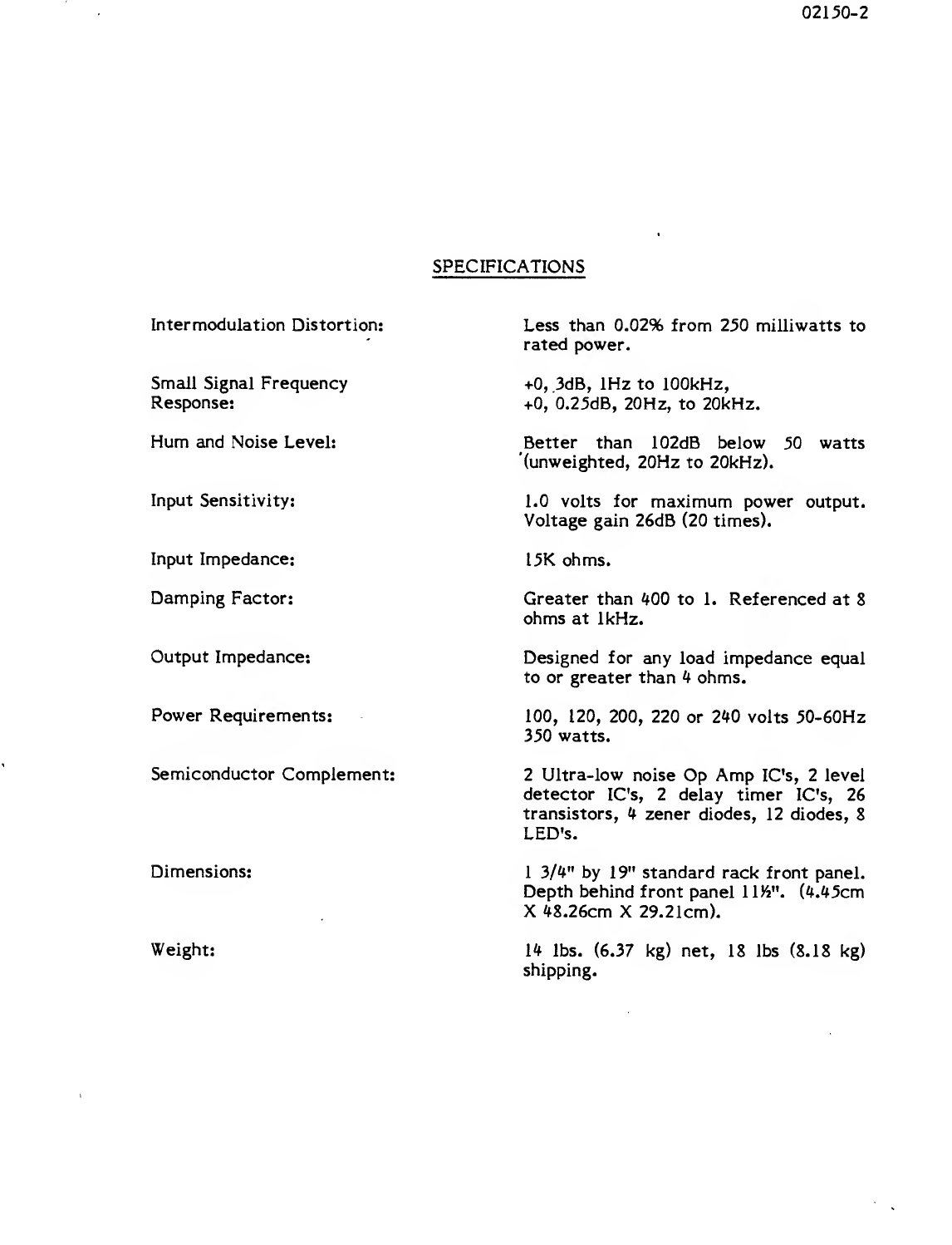
SPECIFICATIONS
Inter modulation Distortion:
Small Signal Frequency
Response:
Less than 0.02% from 250 milliwatts to
rated power.
+0, 3dB, 1Hz to 100kHz,
+0, 0.25dB, 20Hz, to 20kHz.
Hum and Noise Level:
Input Sensitivity:
Better than 102dB below 50 watts
(unweighted, 20Hz to 20kHz).
1.0 volts for maximum power output.
Voltage gain 26dB (20 times).
Input Impedance: 15K ohms.
Damping Factor: Greater than 400 to 1. Referenced at 8
ohms at 1kHz.
Output Impedance: Designed for any load impedance equal
to or greater than 4ohms.
Power Requirements: 100, 120, 200, 220 or 240 volts 50-60Hz
350 watts.
Semiconductor Complement:
Dimensions:
Weight:
2Ultra-low noise Op Amp IC's, 2level
detector IC's, 2delay timer IC's, 26
transistors, 4zener diodes, 12 diodes, 8
LED's.
13/4" by 19" standard rack front panel.
Depth behind front panel IIK
2". (4.45cm
X48.26cm X29.21cm).
14 lbs. (6.37 kg) net, 18 lbs (8.18 kg)
shipping.
02500
UNPACKING AND SET-UP
Your BGW Power Amplifier is shipped in an advanced packing container.
SAVE THE CONTAINER
AND ALL PACKING MATERIAL!
The container should be saved in the event the unit is moved or shipped at some
future date. Replacement containers are available from BGW.
Inspect the unit for damage in transit immediately upon receipt. If damage is
found, notify the transportation company immediately. Only the consignee may
institute aclaim with the carrier for shipping damage. BGW will cooperate fully in
such event. Be sure to save the container as evidence of damage for the shipper to
inspect.
The amplifier's mounting position must be chosen carefully so that the air flow to
the sides of the unit is not restricted. Inadequate ventilation may cause the
protective heat sensors to shut the unit off. For rack mounting, the four rubber
feet on the bottom of the unit may be removed and no hardware will be loosened
inside the unit.
DO NOT PLUG THE AMPLIFIER IN YET!
All connections should be made before power is applied.

02650
RACK MOUNTING HINTS
KEEPING IT COOL
Apower amplifier draws energy from aprimary electrical service, usually a120
VAC outlet, to drive loudspeaker systems with an audio signal. Typically, only half
of the energy can be delivered to the loudspeakers; remaining energy is converted
into heat, and must be dissipated (ventilated) into the air.
Air circulating past heat-producing components, absorbs the heat and carries it
away. To accomplish this, low and medium power amplifiers rely on natural
convection currents, while most high power amplifiers use fans. If the air flow is
impeded, the resulting rise in heat may cause an amplifier to stop working or fail.
Circulating air currents must not be cut off when installing power amplifiers in
racks. Power amplifiers using convection cooling require spacing between
amplifiers to permit air flow between them. Power amplifiers using forced-air
cooling, on the other hand, can usually be stacked closer to each other and may not
need any blank panel spacing between amplifiers.
To improve natural convection currents within arack, achimney can be created by
closing the back of the rack and venting the rack at the bottom to let in fresh air,
and at the top to exhaust hot air. Vents should be large rectangular slots
approximately 19" wide by 4" high.
The rack cabinet will require some type of blower if alarge air-flow is required. It
is best to exhaust air from the top of the rack rather than to blow it in from the
bottom. There will be less dust and dirt in the rack this way, if the bottom vent is
sufficiently large.
INSTALLING THE UNITS
Use care when mounting equipment in arack. Place the heaviest units near the
bottom of the rack and fill in all unused rack spaces with blank panels. Equipment
cannot always be supported by front panels alone. This is especially true of
amplifiers whose depth is more than twice their height. Uniform support can be
insured by installing bottom or side rails.
When racks are to be transported or used in amobile installation, some means of
securing the rear of the equipment is required. Angle brackets either attached to
the bottom, side rails or rear panel are practical approaches.
03002-1
STEREO INPUT CONNECTIONS
Three-pin XLR and in. phone jacks are provided on the rear of the amplifier for
input connections. Balanced or unbalanced lines may be used; however if input
cables are longer than 8feet, balanced lines may be necessary to maintain the
signal-to-noise ratio and high frequency response.
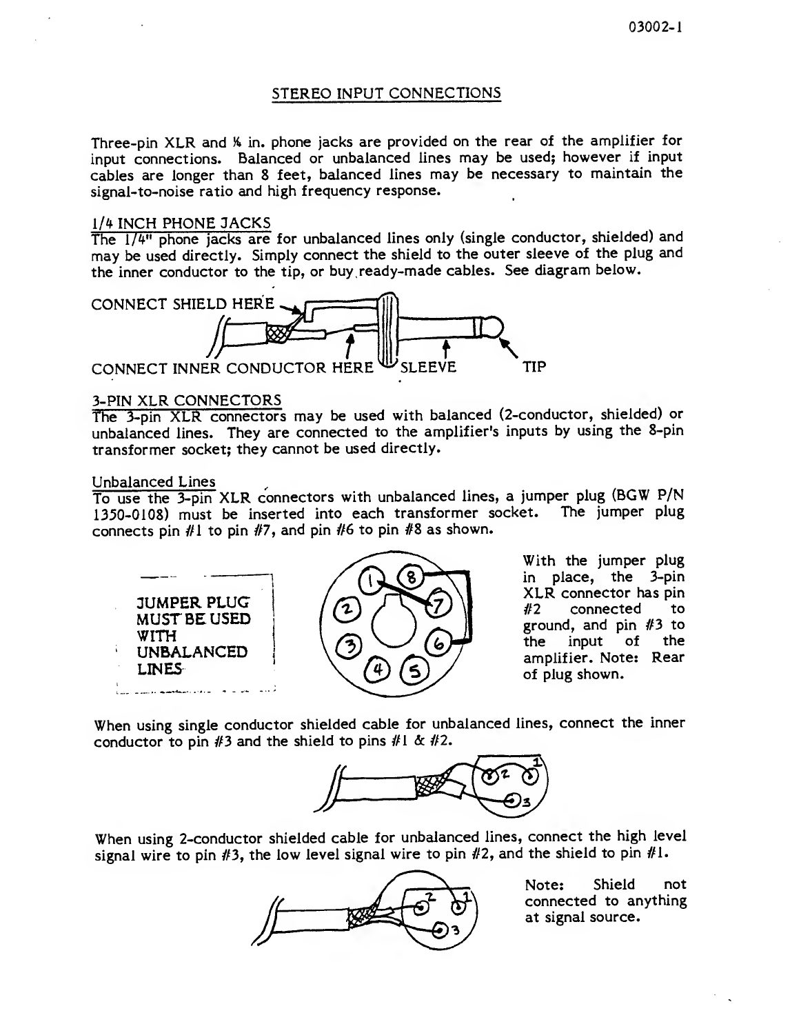
1/4 INCH PHONE JACKS
The 1/4" phone jacks are for unbalanced lines only (single conductor, shielded) and
may be used directly. Simply connect the shield to the outer sleeve of the plug and
the inner conductor to the tip, or buy ready-made cables. See diagram below.
CONNECT SHIELD HERE ms
CONNECT INNER CONDUCTOR HERE ^SLEEVE
ID
f\TIP
3-PIN XLR CONNECTORS
The 3-pin XLR connectors may be used with balanced (2-conductor, shielded) or
unbalanced lines. They are connected to the amplifier's inputs by using the 8-pin
transformer socket; they cannot be used directly.
Unbalanced Lines
To use the 3-pin XLR connectors with unbalanced lines, ajumper plug (BGW P/N
1350-0108) must be inserted into each transformer socket. The jumper plug
connects pin //I to pin #7, and pin //6 to pin #8 as shown.
JUMPER PLUC
MUST BE USED
WITH
UNBALANCED
LINES
With the jumper plug
in place, the 3-pin
XLR connector has pin
#2 connected to
ground, and pin //3 to
the input of the
amplifier. Note: Rear
of plug shown.
When using single conductor shielded cable for unbalanced lines, connect the inner
conductor to pin #3 and the shield to pins #1 &// 2.
When using 2-conductor shielded cable for unbalanced lines, connect the high level
signal wire to pin //3, the low level signal wire to pin //2, and the shield to pin //l.
Note: Shield not
connected to anything
at signal source.

03002-2
To achieve atrue balanced input, it is necessary to use one transformer for each
input. These should be plugged into the octal sockets provided. Depending on the
specific application, one of several different transformers may be selected.
Forms are included in this manual to help guide you in your use and selection of
transformers. Use the index below to find the appropriate form to match your
needs.
CONNECTING ON SOURCE TO ONE AMPLIFIER
Using Balanced Lines; Refer to form #03031
Using Unbalanced Lines: Refer to form #03041
CONNECTING ONE SOURCE TO TWO OR MORE AMPLIFIERS OR DEVICES
Using Balanced Lines; Refer to form #030 1
1
Using Unbalanced Lines; Refer to form #03021
NOTE: Each amplifier input will be referred to as the "Load" in the above
mentioned forms. Only one channel will be shown.
Two conductor shielded cable should be used in abalanced line system. Connect
input cables as shown below.
Pin #1 Shield (Ground)
Pin #2 Signal (Minus)
Pin #3 Signal (Plus)
FOR MONO (BRIDGED) OPERATION
To operate the unit as amono amplifier, use the left channel input only. DO NOT
use the right channel input. Remember to place the stereo/mono switch in the
mono position.

BRIDGING BALANCED LINE INPUTS
Used only when two or more devices are driven from the same input line.
MAXIMUM NUMBER OF AMPLIFIER 25ea
Input transformers for above
A. Use 1:1 transformer 600 ohms to 600 ohms
B. Nth load must have aterminating resistor added to the secondary
of the Input transformer.
One alternative configuration is
C. 1:1 transformer 15K ohms to 15K ohms
D. Nth load must have aterminating resistor added to the primary
of the input transformer.
To find this resistance value see sheet TERMINATING RESISTANCE CHART,
MFRM 03051.
NOTE: Terminating resistance is required when source is atransformer. Sources
other than a transformer may not need atermination.
03021
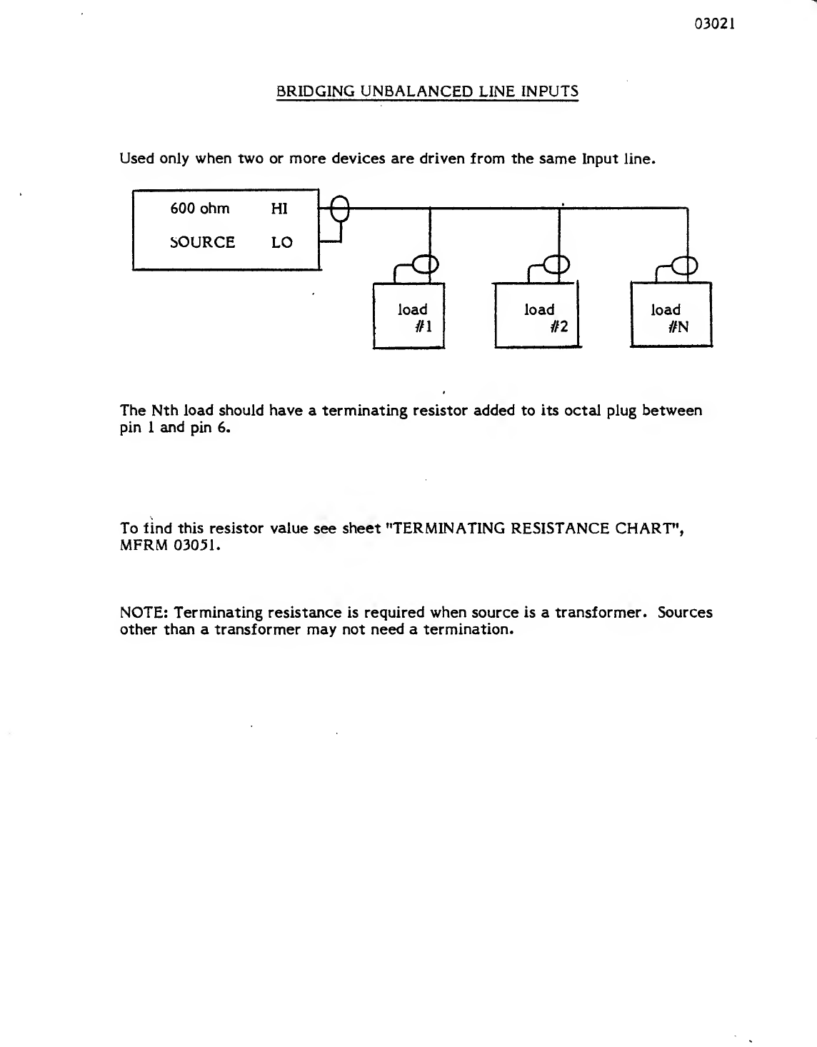
BRIDGING UNBALANCED LINE INPUTS
Used only when two or more devices are driven from the same Input line.
The Nth load should have aterminating resistor added to its octal plug between
pin 1and pin 6.
To find this resistor value see sheet "TERMINATING RESISTANCE CHART",
MFRM 03051.
NOTE: Terminating resistance is required when source is atransformer. Sources
other than atransformer may not need atermination.

03031
BALANCED LINE INPUT:
Used only when one amplifier is driven from one source.
600 ohm
Source
A^
LOAD
X1L
Input transformer for above
A. Use 1:5 transformer 600 ohms to 15K ohms
NOTE: No 600 ohm TERMINATION IS REQUIRED
B. Alternate transformer
Use 1:1 transformer 600 ohms to 600 ohms
NOTE: 600 ohms termination is required on the secondary of the transformer
NOTE: Terminating resistance is required when source is atransformer: sources
other than atransformer may not need atermination.
600 ohm termination, when required, can be accomplished by soldering the resistor
across pins 1and 6of the transformer as shown below
or by installing the resistor in a1/4" phone plug and inserting it into the unused
unbalanced input jack.

03041
UNBALANCED LINE INPUT
Used only when one amplifier is driven from one source
600 ohm
Source
A600 ohm terminating resistor must be added to its octal plug.
Between pin 1and pin 6
NOTE: Terminating resistance is required when source is atransformer. Sources
other than atransformer may not need atermination.

03051
TERMINATING RESISTANCE CHART
How to find terminating resistance for balanced or unbalanced 600 ohm
lines, driving more than one amplifier.
STEP AInput Impedance of Amplifiers Total Load Impedance
Number of Amplifiers “of Amplifiers
STEP BTotal Impedance of Amplifiers -600 K(Impedance Factor)
STEP C
™~60(5 “
(i+l)x 600 ohms =Load Resistor Required
EXAMPLE:
Input Impedance of Amplifiers =15,000 ohms
Number of Amplifiers =4
A1M92. -3750 ohms
B3750-600 e
Too =5-25
Cx600 =1.19 x600 =714.29 ohms
Closest value is 715 ohms 1% metal film resistor.
*Note ail amplifiers must have the same input impedance. If not, use
formula below:
30k and 7.5k
1
X+
+
X
Zi Zj Zu
EXAMPLE:
Total Load Impedance
Four (4) Amplifiers with input impedance of 15k, 30k,
1
lfffc 50K. 50(C 7.SK
=3750 ohms

03501-1
STEREO OUTPUT CONNECTIONS
Two sets of five-way binding posts, on the rear panel, serve as output connectors,
with one black and one red binding post for each channel. Left channel leads go to
the binding posts marked LEFT; right channel, to those marked RIGHT.
Output leads are best connected, to the amplifier, with standard banana plugs;
however, the five-way action of the binding posts permits the use of tinned wires
or spade lugs.
Make certain that the speakers are properly phased. Connect the black or minus (-)
terminal on the speaker cabinet to the appropriate black binding post on the
amplifier. Connect the red or plus (+) terminal to the red binding post. Check to
see that the stereo-mono switch on the rear of the amplifier is in the stereo
position.
SPEAKER PROTECTION
All speakers can be damaged by having too much power applied to them. Fuse
protection is an effective and inexpensive way of preventing this from occurring.
If your speaker system does not contain a fuse or acircuit breaker, afuse should be
placed in series with each speaker and the wire going to the red terminal on the
rear of the amplifier.
Maximum protection can be obtained with fast-acting fuses. Use the value
recommended by the manufacturer. If no value is specified, use the chart provided
to select the correct value (MFRM-03530).
To use the chart, take astraightedge, such as aruler, and line up the speaker's
impedance with its peak music power rating. The proper fuse value can then be
read from the center column. Choose afuse that is closest to, and below, the
value indicated.
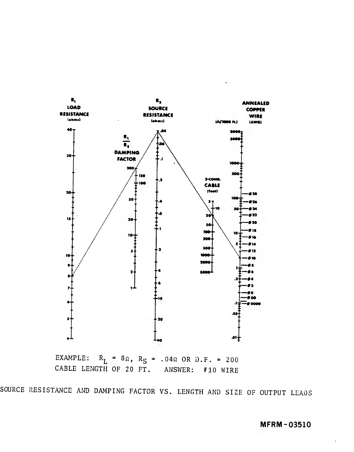
WIRE SIZE AND DAMPING FACTOR
The high damping factor of BGW amplifiers results in avery clean bass response.
Excessively long, and small diameter speaker wires can lower the damping factor
and distort the lower frequencies. Adamping factor of at least 50 should be
maintained to insure good audio quality.
The relationship between wire length and diameter, and damping factor can be
calculated using the chart (MFRM-03510) on the following page. Proceed as
follows:
1. Using astraight-edge, line up the gauge of the speaker wire with its length.
Mark off the resulting source resistance where this line crosses the center
column.
2. Line up the source resistance, determined in step #1, with the
manufacturer's impedance* of the speaker system. The damping factor can
now be read.

03501-2
The impedance of aspeaker system can be approximated by measuring the resistance
across the speaker terminals, with the amplifier disconnected. Multiplying this
result by 1.33, gives you the approximate impedance.
Note: This method cannot be used with electrostatic speakers.
«l
LOAD
RESISTANCE
(•tents)
*» ANNEAUD
SOURCI COSSCR
RESISTANCE WIRE
{A/1000 HJ (AWOt
EXAMPLE: \=8«, Rs=.04s? OR D.F. =200
CABLE LENGTH OF 20 FT. ANSWER: #10 WIRE
SOURCE RESISTANCE AND DAMPING FACTOR VS. LENGTH AND SIZE OF OUTPUT LEADS
MFRM -03510
Other manuals for 150
2
Table of contents
Other BGW Amplifier manuals


