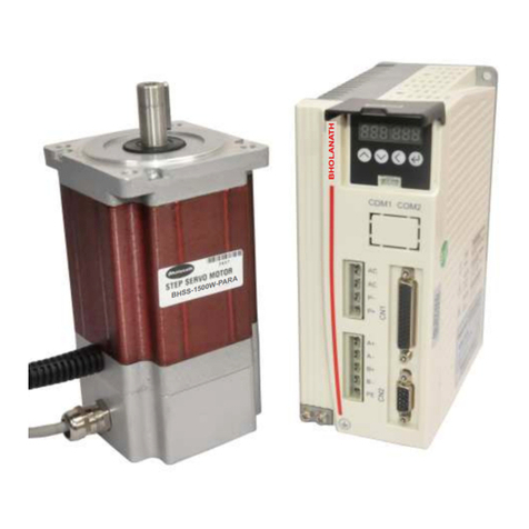
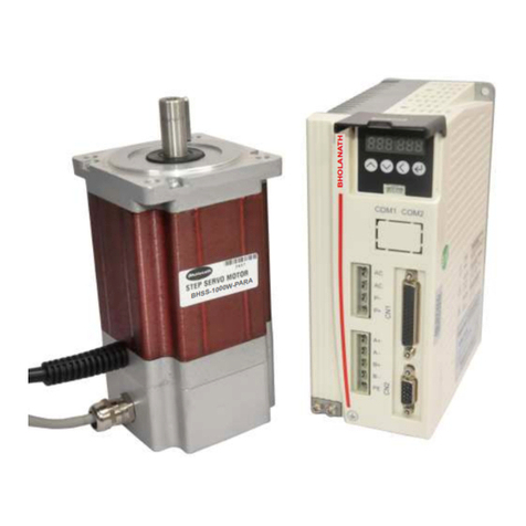
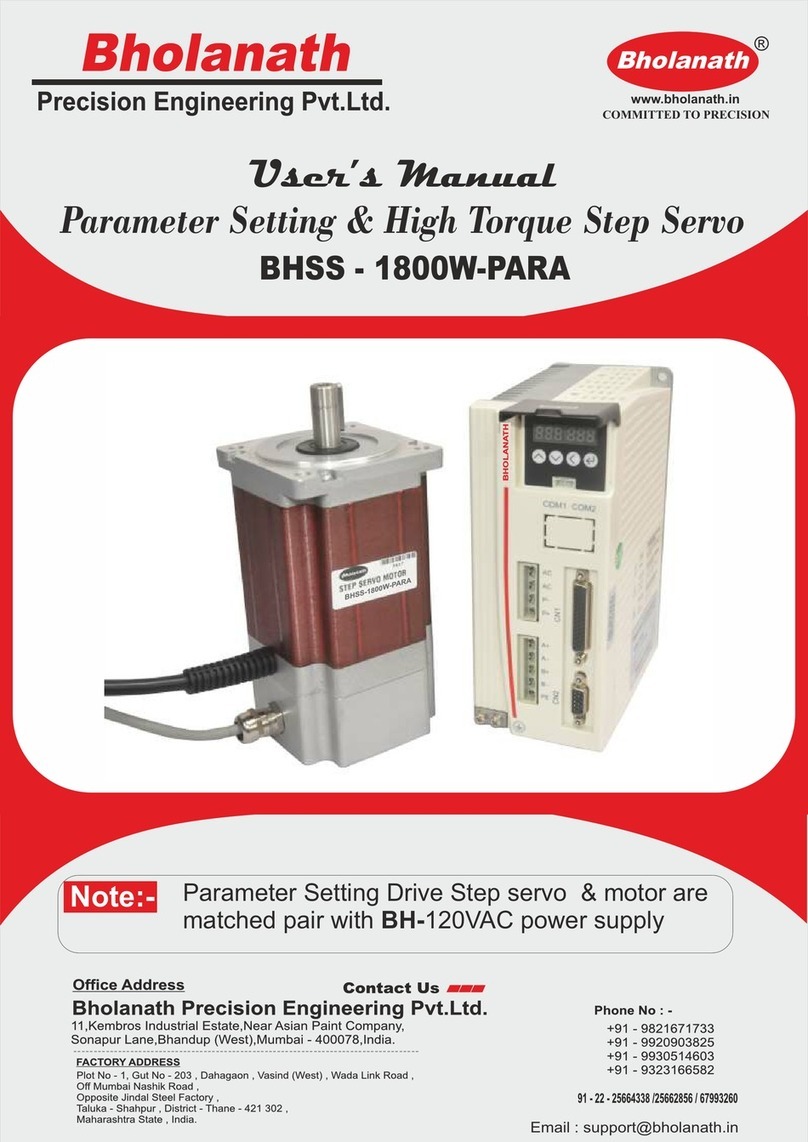
Bholanath BHSS-2500W-PARA User manual

Bholanath
COMMITTED TO PRECISION
®
www.bholanath.in
Email : [email protected]
Parameter Setting Drive Step servo & motor are
matched pair with BH-120VAC power supply
Note:-
Parameter Setting & High Torque Step Servo
BHSS - 2500W-PARA
User’s Manual
BHOLANATH
BHSS-2500W-PARA

Content
Foreword ......................................................................................................................................... 3
1 Overview
BHSS-2500W-PARA
................................................................
.................................................
................................
................................
................................
................................
......
......
5
5
1.1 Product Description ............................................................................................................... 5
1.2 Feature ................................................................................................................................... 5
1.3 Application field ...................................................................................................................... 5
2 Performance Indicators ............................................................................................................. 6
2.1 Electrical Characteristics ....................................................................................................... 6
2.2 Working Environment ............................................................................................................ 6
3 Installation.................................................................................................................................... 7
3.1 Installation Size ...................................................................................................................... 7
3.2 Installation Method................................................................................................................. 7
4 Port and wiring ............................................................................................................................ 8
4.1 Wiring diagram ....................................................................................................................... 8
4.2 Port definition ......................................................................................................................... 8
4.2.1 Power input port and motor output port ........................................................................ 8
4.2.2 Encoder feedback port ................................................................................................... 9
4.2.3 Control signal port .......................................................................................................... 9
4.2.4 Status Indicator ............................................................................................................... 10
4.2.5 Button X4 ........................................................................................................................ 10
5 Menu Operation ........................................................................................................................... 11
5.1 Operation interface ................................................................................................................ 11
5.2 Menu introduction .................................................................................................................. 11
5.2.1 System monitor menu items dP- ................................................................................. 12
5.2.2Parameter setting menu PA-......................................................................................... 13
5.2.3 Parameter management menu EE- ............................................................................ 17
5.2.4 Internal test menu item Sr- .......................................................................................... 18
5.2.5 History fault display dE- ............................................................................................... 18
6 Encoder Cable Specifications ............................................................................................. 19
7 Common faults and handling ................................................................................................. 20
7.1 Troubleshooting ................................................................................................................... 20
7.2 Fault analysis and solution.................................................................................................. 21
Bholanath
COMMITTED TO PRECISION
®
www.bholanath.in

Foreword
Thank you for using our easy servo drive.
Before using this product, be sure to read the manual to learn the necessary safety
information, precautions, and operating methods.
Incorrect handling may lead to extremely serious consequences.
Statement
This product is designed and manufactured without the ability to protect personal safety
from mechanical system threats. Users are advised to consider safety precautions
during use to prevent accidents caused by improper operation or product abnormalities.
Due to product improvements, the contents of this manual are subject to change without
notice.
Our company will not be responsible for any modification of the product by the user.
When reading, please pay attention to the following signs in the manual:
Notice: Remind you to pay attention to the main points in the text.
Caution: Indicates that incorrect operation may result in personal injury
and equipment damage.
Bholanath
COMMITTED TO PRECISION
®
www.bholanath.in
3
INDEX

BHSS - 2500 W-PARA STEP SERVO MOTOR
BHOLANATH STEP SERVO MOTOR BHSS - 2500 W-PARA
SERVO MOTOR 2500 WATTS
TECHNICAL DATA
Power Input - BH-120Vac
Characteristics
Encoder Options - 1000 PPR/2500 PPR
Cable Length - 3 / 5 Meters
Motor - Bipolar Hybrid Stepper Motor
Step Angle - 1.8 Degree
Degree Of Protection - DIN 40050 IP 60 / IP 65
Insulation Class - H
Weight - 10.5 Kg
Current Per Phase - 8.0 A
Torque - 30 Nm - 10.2 Nm
RPM - 0 - 1200
Stock Temperature - ( - 10° C to + 70° C )
Operation Temperature - ( - 10° C to + 40° C )
Shaft Axial Play - 0.08 Max.Play (450 G Load)
Shaft Radial Play - 0.02 Max.Play (450 G Load)
Max. Radial Force - 220 N (20 MM from Front Flange)
Max. Axial Force - 60 N (20 MM from Front Flange)
Motor Options Available -
Standard Model - S
With Low Backlash Planetary Gearbox - PL
With Electro Magnetic Brake - BR
With Helical Gearbox - HL
CE Certificate - N - STANDARD/CE - CERTIFIED
BHSS- 2500 W - S - 1000 - 3MTR.- IP 60-NORDERING CODE -
Closed Loop Stepping System which includes High Speed (>1200 RPM)Stepper Motors with
Incremental Optical Encoders,Digital Drives and 3 Meter Cable.
SUITABILITY - The BHSS - 2500 W-PARA Step Servo is comparable to 2500 Watts Servo Motor
upto 350RPM.The Step - Servo Motor BHSS - 2500 W-PARA gives more torque at lower RPM’s
thus giving abetter performance than 2500 Watts Servo Motors as seen in the graph.
4
TORQUE (Nm)
Bholanath
COMMITTED TO PRECISION
®
www.bholanath.in
4
INDEX
BHOLANATH
BHSS-750W-PARA
40
201
0
5
10
15
20
25
10 50 100 200 300 400 500 600 700 800 900 1000
RPM

1 Overview
1.1 Product Description
The servo stepper drive system combines the advantages of open-loop stepper and
servo control, and is particularly suitable for the upgrade of open-loop stepper drive
control and the cost reduction of traditional servo control.
1.2 Feature
l Digital PI current loop, low noise.
l Three operating modes:
- Self-operating mode: The motor can be triggered by a pulse signal. When
the pulse signal optocoupler is turned on, the motor starts self-run
according to the parameter setting of PA-45~PA-53; when it is turned off,
the motor stops self-running.
- Open loop mode: for testing and emergency use. The motor temperature
rise is higher.
- Position mode: This mode is the default mode of the drive and is suitable for
most occasions. When the driver works in this mode, the motor does not
lose step, the temperature is low, and the high and low speed performance
are better than the open loop mode.
l The microstep setting can be any number between 400-60000.
l Protection functions such as overcurrent, phase error, overvoltage and position
deviation error.
l 6 digital LED display, which can easily set parameters and monitor motor
running status.
l Pulse command averaging filter, the filter can turn the curve without
acceleration and deceleration into a trapezoidal acceleration/deceleration curve,
which greatly smoothes the motion. The trapezoidal acceleration/deceleration
curve is filtered to become a smoother S-shaped acceleration/deceleration
curve. Especially suitable for point-to-point sports occasions.
l Three types of pulse command: pulse + direction, double pulse(CW/CCW) and
quadrature input.
1.3 Application field
Mainly used in robots, industrial robot arms, engraving machines, wire stripping
machines, marking machines, cutting machines, plotters, CNC machine tools, automatic
assembly equipment and pattern machines.
Bholanath
COMMITTED TO PRECISION
®
www.bholanath.in
BHSS-1000W-PARA (Parameter) belongs to easy servo (servo-stepper) drives. With new generation
of 32-bit DSP motor control technology, which completely overcomes the problem of lost step of
open-loop stepping motor, BHSS-1000W-PARA greatly improves the high and low speed performance
and torque utilization rate of stepping motor, and effectively reduces motor heat.
5
INDEX

2 Performance Indicators
2.1 Electrical Characteristics
Parameter BHSS-1000W-PARA
Minimum value Typical value Maximum value Unit
Continuous Output
Current 0 - 6.5 A
Input Supply
Voltage 120 Vac
Logic Input
Current 7 10 20 mA
Logic Input
Voltage 0 - 200 kHz
Pulse Frequency 500 MΩ
2.2Working Environment
Cooling Method Natural cooling or external heat sink
Working
Environment
Working
occasion
Keep away from other heating equipment as far
as possible to avoid dust, oil mist, corrosive gas,
strong vibration, flammable gas and conductive
dust
Temperature 0°C-50°C
Humidity 40-90%RH
Vibration 5.9 m/s2 Max
Storage
Temperature
-20°C-+80°C
Weight Around 1000g
Bholanath
COMMITTED TO PRECISION
®
www.bholanath.in
6
INDEX

3 Installation
3.1Installation Size
Back Side
Installation dimension drawing (unit: mm)
3.2Installation Method
Install the drive with the upright side installation to create a strong air convection on
the surface of the heat sink; if necessary, install a fan near the drive to force heat
dissipation to ensure that the drive works within a reliable operating temperature range
(The reliable operating temperature of the drive is usually within 60 ° C and the motor
operating temperature is within 80 ° C).
Bholanath
COMMITTED TO PRECISION
®
www.bholanath.in
168
180
76
64
6
139.2
BHSS-PTR
Input supply Voltage: 110VAC
7
INDEX

4 Port and wiring
4.1 Wiring diagram
Drive wiring diagram
Note:
l Personnel involved in the wiring must have the professional ability.
l Input voltage should not exceed AC 110V.
4.2 Port definition
4.2.1 Power input port and motor output port
No. Symbol Name Definition
1 AC Power input port Connect 120V AC
2 AC
3 A+
Motor power port
Connect motor Green line
4 A- Connect motor Black line
5 B+ Connect motor Red line
6 B- Connect motor Blue line
Status indicaon interface
Control signal port
Button X4
Encoder input port
Power input port
Motor output port
Bholanath
COMMITTED TO PRECISION
®
www.bholanath.in
8
INDEX

Note:
l Must use the matching BHOLANATH motor, if the user uses other motor and
caused an accident, Bholanath shall not be responsible.
4.2.2 Encoder feedback port
Encoder extension cable provided by Bholanath (please refer to 6.2 Encoder Extension
Cable Specifications for reference), connect the encoder extension cable directly to the
motor encoder and drive.
4.2.3 Control signal port
The correspondence definition of each control signal is as follows:
1
2
3
4
5
6
7
8
9
1 0
1 1
1 2
1 3
1 4
1 5
1 6
1 7
1 8
1 9
2 0
21
2 2
2 3
2 4
2 5
2 6
2 7
2 8
2 9
3 0
31
32
33
3 4
35
3 6
3 7
3 8
39
40
4 1
42
43
44
No. Symbol Name Definition
3 5PU+ Pulse 5V positive input Pulse signal
(input signal)
4 PU- Pulse negative input
19 24PU+ Pulse 24V positive input
5 5DR+ Direction 5V positive input Direction signal
(input signal)
6 DR- Direction negative input
21 24DR+ Direction 24V positive input
11 5MF+ Enable 5V positive input Enable signal
(input signal)
12 MF- Enable negative input
27 24MF+ Enable 24V positive input
13 5CLR_A+ Deviation clear 5V positive
input Deviation clear
signal
(input signal)
14 CLR_A- Deviation clear negative
input
29 24CLR_A+ Deviation clear 24V positive
input
9 PEND+ In-position signal positive
output In-position signal
(output signal)
10 PEND- In-position signal negative
output
7 ALM+ Alarm signal positive output Alarm signal
(output signal)
8 ALM- Alarm signal negative output
41 S-OFF+ Motor brake control signal
positive output Motor brake
control signal
(output signal)
42 S-OFF- Motor brake control signal
negative output
16 A+ Encoder A channel positive
outputting
Encoder pulse
differential (output
signal)
31 A- Encoder A channel negative
Bholanath
COMMITTED TO PRECISION
®
www.bholanath.in
9
INDEX

outputting
18 B+ Encoder B channel positive
outputting
32 B- Encoder B channel negative
outputting
34 Z+ Encoder Z channel positive
outputting
35 Z- Encoder Z channel negative
outputting
39 PZOut Encoder Z channel
single-ended output
Encoder Z
channel
single-ended
output (output
signal)
In order to avoid some wrong actions and deviations, PU, DR and MF should meet
certain requirements, as shown in the following figure:
4.2.4 Status Indicator
PARA has a 6-digit LED to display the status. When the drive fails, the drive will
stop and show corresponding fault code; the drive will save the latest fault in the
EEPROM of the drive according to the queue form, and the drive can save up to 10 latest
history failure.
4.2.5 Button X4
button display panel to implement the
functions of up, down, shift/cancel and confirm. For details, see Chapter 5: Menu
Operation.
PUL
DIR
MF
Bholanath
COMMITTED TO PRECISION
®
www.bholanath.in
10
INDEX
There are four touch buttons on the PARA

5 Menu Operation
5.1 Operation interface
shift/cancel and confirm functions. As shown below:
MS S3-
The table below shows the function of each button:
Buttons Name Function
up page Switch up in the menus at the same level or
increase parameter value
down page Switch down in the menus at the same level or
decrease parameter value
shifting Short press this key to shift in parameter set
cancel Long press this key to return to the previous menu
or cancel the operation
confirm Enter the next menu or to confirm the operation
5.2 Menu introduction
There are three levels for system menu. Level 1 menu contains 5 item, the menu
items can be switched up and down by button up page and button down page
. Press confirm button once, to go to the next menu. Long press to
return to the previous menu. Short press on other menu to return to previous
directory.
dP -
dE-
Sr -
Up
Down
Confirm
Shi/Cancel
Bholanath
COMMITTED TO PRECISION
®
www.bholanath.in
11
INDEX
There are four touch buttons on the PARA button display panel to achieve up, down,

EE-
PA -
dP -
5.2.1 System monitor menu items dP-
dP- : Under this menu, ther’re total 12 second-level items, you can monitor 11
system State. Under the first-level menu, press and to select dP–menu item.
And then press to enter dP- menu secondary menu. Secondary menu as shown in
the following table:
Level 1
menu Level 2 menu Meaning Remark
dP -
dP – SPd Motor real time speed (r/min)
dP – SPr Given speed (r/min)
dP – PoS Current position low 4 bit (Encoder
pulse number)
dP – PoS. Current position high 4 bit
(Encoder pulse number)
dP – CPo Position command low 4 bit
(Command pulse number)
dP – CPo. Position command high 4 bit
(Command pulse number)
dP – EPo Position deviation low 4 bit
(Encoder pulse number)
dP – EPo. Position deviation high 4 bit
(Encoder pulse number)
dP – I Motor current (mA)
dP – bUS Drive internal bus voltage (V)
dP – Err Error code
00——No error
01——Memory read
error
02——Overvoltage
protection
04——Encoder failure
05——Overcurrent
protection
07——Position
tolerance protection
08——Motor wiring
wrong phase
Bholanath
COMMITTED TO PRECISION
®
www.bholanath.in
12
INDEX

dP – VEr Software Version
After entering the secondary menu, by press and to select the item that
you want to view the status, and then press the button, the display shows the
status value. If you want to exit, press .
5.2.2Parameter setting menu PA-
PA- Menu has 100 second-level menu item, each second-level menu item
corresponds to a system parameter. By press and to select the parameter that
you want to set, then press to enter parameter setup interface.
In the process of setting parameters, short press to shift, by press and
to modify the value. the values displayed will not be applied immediately, only after
the user press button, the values displayed are effectively applied to system. When
you need to exit the parameter setting, please long press .
Bholanath
COMMITTED TO PRECISION
®
www.bholanath.in
13
INDEX

※PA-common parameters list:
No. Name Function Default Range
PA-2 Operation mode
selection
0: Self-running (Triggered by
pulse signal. When the pulse
signal is turned on, the motor
starts to run according to the
parameter settings of PA-45 ~
PA-53; when it is off, the motor
stops running) 2 0~3
1: Open loop mode (run
without encoder line)
2: Servo mode 0
3: Servo mode 1
PA-4 Positional accuracy 2
1~65535
encoder
pulses
PA-6 Electronic gear ratio
numerator 4000 1~65535
PA-7
Electronic gear ratio
denominator (pulse
per round)
When PA-6 is set to 4000,
PA-7 value is equivalent to the
number of pulses required for
one round of the stepper motor
(microstep).
1600 1~60000
PA-8 Encoder resolution 4000 4000
PA-9 Tracking error alarm
threshold
This value can be changed
based on actual need 5000
0~65535
encoder
pulses
PA-10 Current loop Kp 1817 0~65535
PA-11 Current loop Ki 50 0~65535
PA-12 Current loop Kc 256 0~65535
PA-13
Alarm clear signal
(CLR-A) function
selection
0 CLR-A to clear deviation
alarm;
1 CLR-A to change the
direction of the motor rotation
0 0/1
PA-14 Enable (MF)
function setting
1 MF is used as a general
motor release signal
0 MF as a pulse blocking
function
1 0/1
PA-15 Enable (MF) level
selection
0 The default set is: the driver
respond to pulse command
when MF is not connected
1 Respond to pulse
command need 5V MF
signal
0 0/1
PA-16 Alarm signal (ALM) 1 Alarm output ALM normally 1 0/1
Bholanath
COMMITTED TO PRECISION
®
www.bholanath.in
14
INDEX

output level
selection
open
0 Alarm output ALM normally
close
PA-17 Single and double
pulse selection
0 Pulse + direction mode
0 0/1/2 1 Double pulse mode
2 Orthogonal input
PA-18 Pulse valid edge
selection
0 Respond to the pulse
when optocoupler turn
from off to on.
0 0/1
1 Respond to the pulse
when optocoupler turn
from on to off.
PA-19 Motor rotation
direction selection
0 Counterclockwise
1 0/1
1 Clockwise
PA-20 Pulse width filter Filter pulse signal glitches 10 1~128
PA-21
In-position signal
(PEND) mode
selection
0 When the position
deviation is less than the
number of encoder pulses
set by PA-23, it is in
position.
1 No position command,
when the position deviation
is less than the number of
encoder pulses set by
PA-23, it is in position.
2 No position command, and
the position deviation is
less than the number of
encoder pulses set by
PA-23, output in-position
signal until the time set in
PA-24 (in-position hold
time in milliseconds) is
passed. After the holding
time of the in-position signl,
the status is determined by
the position command at
that time and the status of
the position deviation.
1 0~2
PA-22
In-position signal
(PEND) level
selection
0 PEND turns on when in
position
1 PEND turns off when in
position
0 0/1
PA-23 Positioning end
range
To set the in-position pulse
range in controlled position.
For details, refer to PA-21.
5
0~65535
encoder
pulses
PA-24 In-position signal In-position signal holding time,
unit is ms, refer to PA-21 for 10 0~65535
15
INDEX

holding time details.
PA-25 Pulse command
microstep enable
0 microstep enable
1 microstep disable 1 1
PA-28 Pulse command
filtering
Filter time = (PA-28) * 50us.
This filter can change no
acceleration and deceleration
curve into a trapezoidal
acceleration and deceleration
curve, greatly smooth
movement. And change
trapezoidal acceleration and
deceleration curve into a
smoother S-shaped
acceleration and deceleration
curve. Particularly suitable for
point to point occasions.
30 1~2048
PA-45 Start speed
The motor rotates according to
the parameters of PA-45 to
PA-53 when the operation
mode is self-running or when
the Sr-ON (internal test) menu
is executed.
50 0~65535Hz
PA-46 Acceleration time 50 0~65535ms
PA-47 Deceleration time 50 0~65535ms
PA-48 Target speed 1600 0~65535 Hz
PA-49
Running pulse
number (high 2
bytes)
0 0~20000
PA-50
Running pulse
number (low 2
bytes)
1600 0~65535
pulse
PA-51 Intermittent time 100 0~65535ms
PA-52 Repeat time 10 0~65535
times
PA-53 Whether to run back
and forth 0 0/1
PA-56 Open loop current
percentage 100 0~100
PA-57 Closed-loop base
current percentage 60 0~100
PA-58
Closed loop
maximum current
percentage
100 0~100
PA-60
Position error
proportional
coefficient
1024 0~65535
PA-61
Speed error
proportional
coefficient
0 0~65535
Bholanath
COMMITTED TO PRECISION
®
www.bholanath.in
16
INDEX

PA-62 Speed feed forward
coefficient 0 0~65535
PA-63 Vibration damp
coefficient 512 0~65535
PA-64 Integral coefficient
In the point to point movement
occasions, if there’s need for
high positioning accuracy,
please increase this value,
increase it by 10 for each time.
0 0~65535
Note:These parameters need re-power after change:PA-2,PA-17,PA-18,
PA-20.
5.2.3 Parameter management menu EE-
EE- Menu has 6 second-level menu item, as shown in the following table:
Level 1 menu Level 2
menu
Function
EE-
(Parameters
Management)
EE-SEt
Write parameters, it would write parameters from drive
memory to EEPROM parameter area. If you do not do this,
the drive will restore to previous value after re-power.
EE-rd Parameters read, read EEPROM parameter data into
memory.
EE-bA Parameter backup, write parameters from drive memory to
EEPROM backup area.
EE-rS
Restore the backup to memory. This operation does not
write parameter to EEPROM parameter area. If users want
to permanently use EEPROM backup zone data, you need
to perform write operation (EE-SEt).
EE-dEF
Restore the default value of the parameter, it resets all
parameters to the default values are read into memory and
write to EEPROM.
EE-ACL Clearing the history fault
To save parameters, you need to do the following:
l Find level 1 menu of EE-
l Enter to the level 2 menu of EE-SET
l Long press button, StArt will be displayed on the screen. About 3
seconds later, appears FInISH, which represent the parameters
successfully saved.
Bholanath
COMMITTED TO PRECISION
®
www.bholanath.in
17
INDEX

5.2.4 Internal test menu item Sr-
Level 1 menu Level 2
menu
Function
Sr-
(Internal test)
Sr-On The internal test starts and the motor starts running at the
speed set by PA-45~PA-53.
Sr-Off The internal test ends and the motor stops running.
5.2.5 History fault display dE-
To view the latest 10 history of faults saved in drive EEPROM:
Level 1 menu Level 2
menu
Function
dE-
(History fault check)
dE-1
Displays the latest fault code in dE-01; Displays the
second latest fault code in dE-02;
……
dE-2
dE-3
dE-4
dE-5
dE-6
dE-7
dE-8
dE-9
dE-10
Bholanath
COMMITTED TO PRECISION
®
www.bholanath.in
18
INDEX

6 Encoder Cable Specifications
The encoder cable is used to connect the motor encoder and drive. The figure below
shows the encoder cable size drawing. The standard encoder cable length is 2m, and
other specifications such as 3m, 4m, 5m, 8m, 9m, 10m, 12m, 14m are available.
D B- 1 5P
Encoder Wiring
1
2
3
4
5
6
7
8
9
1 Red EA+
2 Green EA-
3 Brown EB+
4 Yellow EB-
5 White +5VCC
6 Black EGND
Bholanath
COMMITTED TO PRECISION
®
www.bholanath.in
19
INDEX

7 Common faults and handling
Caution:
l The drive and motor must be powered off for at least 5 minutes before
touching the drive and motor to prevent electric shock and burns.
l After the drive fault alarm, it must be eliminated according to the alarm code
before it can be put into use again.
7.1Troubleshooting
Does the LED display an error
code?
Is the supply voltage within the voltage range
required by the drive?
Is the power input connected?
Is the connecon loose?
Is the connecng part loose, disconnected,
broken, or shorted?
Is the wiring correct?
Is the control
signal port wiring
correct?
Is the connecng
part off,
disconnected, or
shorted?
Is the encoder
feedback port
loose or
disconnected?
Is the connecon loose?
Does the motor have an abnormal
sound?
Does the electromagnec brake
operate?
Is the encoder feedback
extension cable interface
loose or disconnected?
Encoder Motor
Bholanath
COMMITTED TO PRECISION
®
www.bholanath.in
20
INDEX
Table of contents
Other Bholanath Servo Drive manuals
Popular Servo Drive manuals by other brands
E.H. Wachs
E.H. Wachs MDSF user manual
SMC Networks
SMC Networks IN-777 Series Operation manual
Leadshine
Leadshine iSS57 Hardware installation manual
Inovance
Inovance SV670P Series Maintenance Guide

Mitsubishi Electric
Mitsubishi Electric MELSERVO-J4 series instruction manual
Siemens
Siemens SINUMERIK 880 installation guide
