BHV XRot-Pro User manual

XRot-Pro
MODEL:
XRot
Pro
Parts code: OM - 6200 - 64 - V2 - GB
Publishing date: 15 August 2021 (rev.HSE)
Printed in Italy
Overseas Business Division
P.le D. Luigi Sturzo, 15
00144 Roma - Italy
Phone +39-0444-885-722
Fax: +39-0444-885-482
BARBIERI Srl
MADE IN ITALY
User Manual
RADIO-CONTROLLED
GRASSLAND MOWER

11
SAFE OPERATION
SAFETY QUICK REMIND
SAFE AREA
SAFE AREA
50m
Gefahr
Peligro
Danger
Pericolo
SAFE AREA SAFE AREA
20m
Gefahr
Peligro
Danger
Pericolo
20m
20m
45° Stability safe limit
35° Fuel supply limit (engine could stop)
20° Lubrication limit (downhill)
6202542
314813
6202543
6201855
TORQUE 130 Nm
96 lbf ft
35°
45°
45° 20°
Slope limitation
Replacing parts for safety
Safe and Danger area
1
A - INTRODUCTION
INTRODUCTION
This handbook must be considered as part of the machine. The seller of
new and second-hand machines must record in the selling document that
this booklet has been given along with the machine.
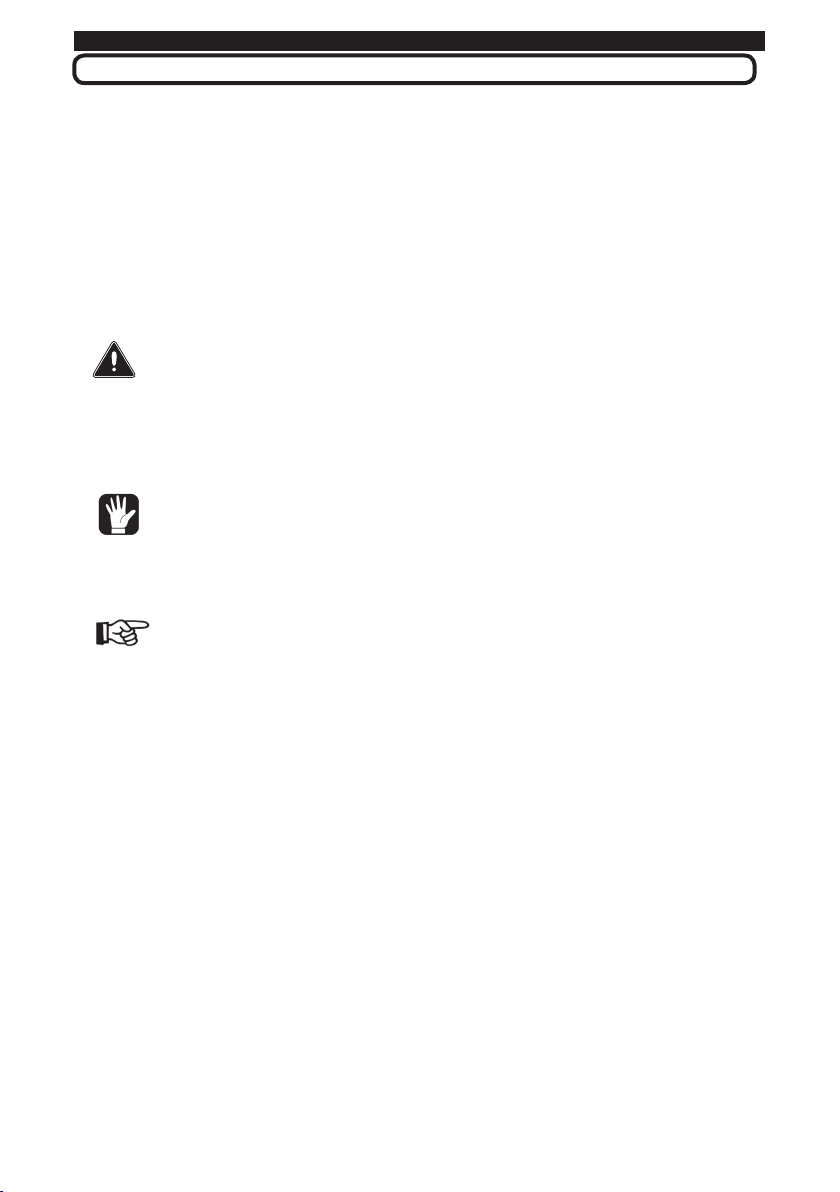
PICTURES USED IN THE HANDBOOK
Before starting use this machine, it is necessary to read carefully
this hand-book, learn and observe all the safety rules indicated with the
following symbols.
DANGER This symbol is used to highlight an important safety
information. If this information is ignored, people are in danger either
of possible injures - even serious ones - or death.
In these messages are also described the normal
precautions which have to be taken to avoid the danger.
Ignoring these precautions can cause serious
damages to the machine.
ATTENTION This warning is used in the handbook safety
messages when the danger can cause minor or moderate damages
and injuries.
The message can be used also for dangers which
can cause damages to the machine or its components.
IMPORTANT It is used for precautions which have to be
taken to avoid operations which can shorten the life of the machine
or of its component.
NOTE This word is used to highlight information which
refers to operations in progress.
Any time you see these symbols, whether on the machine or on the
following of this manual you must pay attention to avoid danger to yourself
and to other people.
Following some rules suggested by the common sense, you will avoid any
break risk and your machine will function longer and more efficiently.
A - INTRODUCTION

2
B - CONDITIONS AND LIMITS OF USE
DEFINITION OF PROPER USE
• This machine have been designed for grass cutting and weed control in
agriculture and public green, flat and sloped areas.
• The exact observance of use conditions, maintenance and reparation are
the essential element for a correct use.
• The machine should be used, maintained and repaired only by people who
have knowledge of the security rules.
• The general rules about accident prevention and public road circulation
rules should be respected
IMPROPER USES
• Any other use is not allowed. The manufacturer is not responsible for
damages caused by any use than the intended one. The user is fully
responsible for any possible risk.
• Each arbitrary modification carried out on the machine could release the
manufacturer from the responsibility for any damage or accident derived by
the machine.
ONLY ONE OPERATOR
The machine was designed to be used by one operator only. The presence of
other people in the closeness could be dangerous for the safety of both user
and people.
ACCESSORIES ON THE MARKET (ONLY IF AUTHORIZED)
Any use of accessories different from the authorized ones by the manufacturer
is not allowed. For further applications different from the authorized one or
in case of misunderstanding of this handbook, please contact the technical
department of the manufacturer.
BARBIERI s.r.l. - Technical department
36040 SOSSANO - (Vl) - ITALY
Tel: 0444/885722 - Fax: 0444/885482
e-mail [email protected]
Descriptions, figures and technical features mentioned herein are non-
binding for the Manufacturer. These are mentioned as mere information.
The Manufacturer reserves the right to make any change at any time
without notice, to improve the quality of the products without being bound
to update this publication.
B - CONDITION AND PROPER USE

3
C - INDEX
A- INTRODUCTION
B- CONDITIONS AND PROPER USE
C- INDEX OF CONTENT
D- MACHINE IDENTIFICATION
o Chassis number
o Type and serial number of the engine
o Dimensions
SECTION 1 - TECHNICAL DATA
1.1 Technical data
1.2 Noise
1.3 Vibrations
SECTION 2 - SAFETY RULES
2.1 Safety parts
2.2 Safety labels and safety advices
SECTION 3 - MACHINE PREPARATION
3.1 Packaging and endowment
3.2 Preliminary tests
SECTION 4 - CONTROLS
4.1 Name of the Major Components
4.2 Engine
4.2.1 Air Filter
4.2.2 Fuel Tank
4.3 Mower Deck
4.4 Electric System
4.5 Transmission
4.6 Remote Control
SECTION 5 - RULES FOR A SAFE USE
5.1 Connect the Radio Control
5.2 Engine start
5.3 Engine stop
5.4 Drive
5.5 Drive in a slope
5.6 Brakes system and Parking
5.7 PTO (Mowing blade switching ON)
5.8 Cutting height adjustment
5.9 Aux port
5.10 Controls during the use
5.11 Access to the work field
5.12 Safety in work field
C - INDEX OF CONTENT
SECTION 6 - TROUBLESHOOTING
SECTION 7 - MAINTENANCE
Main Maintenance components
Lubrification Points
Electric scheme
7.1 Tests before use
7.1.1 Control of the engine oil
7.1.2 Engine's air filter
7.1.3 Refuelling
7.1.4 Control of crawler tension and conditions
7.1.5 Radio Control battery charge
7.1.6 Control Cutting blades
7.2 Maintenance and adjustments
7.2.1 Lubrication program
7.2.2 Changing of engine oil and filters
7.2.3 Control and replacement of gear box oil
7.2.4 Lubrication of joints
7.3.5 Air Filter cleaning
7.2.6 PTO Belt tension
7.2.7 Blade sharpening and replacing
7.2.8 Crawler replacement
7.2.9 Replacement of debris flap-guard
7.2.10Use of the tensioner lock
7.2.11Battery of remote Control
7.3 Notice for disposal
SECTION 8 - COMPLAINTS AND WARRANTY
SECTION 9 - CERTIF. OF CONFORMITY

Tiller B70
4
D - IDENTIFICATION NUMBER
In case of a trouble, when You contact Your dealer for a reparation or to ask
for spare parts, it is necessary to identify the machine with the following data:
• Model and chassis number
• Engine type and number
MODEL AND CHASSIS NUMBER
ENGINE TYPE AND NUMBER
(Honda engine) (Kawasaki engine)
DIMENSIONS (cm)
D - IDENTIFICATION NUMBER
1190 (H) 1254 (K) 1314
700
150
G
Fig 1
Fig 2
Fig 3

I. SAFETY
5
SECTION 1 - TECHNICAL DATA
1.1 Technical data
ENGINE GENERATOR
Make HONDA KAWASAKI Generator 1 Phases 68VAC - 80A
Model GXV 390 FS481V Generator 2 Monophase 17VAC - 10A
Engine type Air cooled OHV petrol Air cooled OHV petrol
Pressure lubrication Forced lubrication
Bore x stroke 88 x 64 mm 73 x 72 mm CUTTING DEVICE
Displacement 389 cm3603 cm3 (2 cylinders) Type Mulcher back discharge
Compression ratio 7.7 : 1 Blade type 2 floating Multy-cut - 2600 rpm
Net power 7.6 kW@ 3 600 rpm 9.9 kW@ 3 600 rpm Cutting Width 70 cm (Honda)- 80 cm (Kawa.)
Cont. rated power 5.2 kW@3 000 rpm Height Adjust. 30 ÷ 150 mm stepless electric
Max. net torque 24.2 Nm@2500 rpm 38.4 Nm@1800 rpm Drive By belt with EM Clutch (Ogura)
Ignition system Transistorised Electronic
Starting system Electric START Electric START RADIO CONTROL 2,4 GHz
Air Filter Paper + Foam cartridge Paper + Foam cartridge Transm. technology AFA (Aut. Freq. Adjustment)
Fuel tank capacity 10 Lt 15 Lt Controls Optic - contactless
Fuel cons. @ rat power 2.5 L/hr - 3 000 rpm Radio transm. distance 150 m
Engine oil capacity 1.1 Lt 2 Lt Regulations compl. Dir R&TTE 1999/5/CE
2006/42/CE
PLe categoria 4 /SIL 3
ISO 13849-1:2008 / EN62061:2005”
Weight 1,3 Kg
TRANSMISSION DIMENSIONS
Type Hybrid-Electric motors 48V
with reduction gear
Overall dimensions
(cm)
119 x 131 x 68
125 x 131 x 70
Control Stepless electric - speed control Weight 320 Kg (H) - 370 kg (K)
Speed Range/ Max 0÷ 8 Km/h Soil pressure (g/cm²) 121 - 132
Max Slope 35°Uphill - Longitudinal 45° Crawler contact area (17,5x75/80x2) = 2625-2800 cm²
Tilt ang/h-gravity point 65° / 15cm
Motor type Brushless Perm. Magnetes
Power supply 3 Phases - 4Kw
Motor power 1.5 kW
Driver BHV - 48V 100A
1 - TECHNICAL DATA

Tiller B70
6
SECTION 1 - TECHNICAL DATA
1.2 Noise
The noise level was obtained during the equipment in action, in neutral
position and the results are the following:
Honda engine GXV 390 (4 strokes) with original muffler
- Acoustic pressure level (LpAm) .... 92,7 dB(A)
- Acoustic power level (LwA)...........107,3 dB(A)
Kawasaki engine FS481V (4 strokes) with original muffler
- Acoustic pressure level (LpAm) .... 87,0 dB(A)
- Acoustic power level (LwA)...........107,0 dB(A)
1.3 Vibrations
The vibrations level was obtained with the machine at work at 3060 rpm (85%
of the nominal condition of 3600 rpm) and the results are the following:
- Not applicable
LABELS AND WARNINGS POSITION
Fig 4
FUSIBLES
K
Relaisbuzzer
AC12V/Alternateur
Alim.Radio/recepteur
Aux
Hauteurde coupe
Accélérateur
RelaisPDF
DC12V/ Aux - Freins
DANGER ! DANGER !
Ne pas faire fonctionner le moteur dans un
endroit fermé car les gaz d'échappement
sont mortels.
Assurer une bonne ventilation du lieu.
Faire le plein de carburant à l’extérieur
exclusivement et avant de démarrer le moteur.
Ne pas fumer pendant cette opération ou
lorsque vous manipulez du carburant.
9990677
35° 45°
45° 20°
arrière
arrière
ISO/CD11684
9990617
ISO/CD11684
9997777
9990677
35° 45°
45° 20°
arrière
Radio Control
by
9997777
DANGER ! WARNING !
Do not exceed the maximum slope stated on the label
Never leave the machine with engine running on a slope
Switch the engine OFF on flat ground only.
Drive downhill in reverse, with the machine’s nose upwards
REMOTE CONTROL SLOPE MOWER
Designedin GERMANY - Made in ITALY
I. SAFETY
7
SECTION 2 - SAFETY NORMS
2 - SAFETY NORMS
Fig 5
2.1 SAFETY DEVICES
The terms “FRONT” - “REAR” - “RIGHT” - “LEFT” used in this handbook and
in the spare parts catalogue, are referred to the machine as shown in Fig. 5
SAFETY PARTS
The machine is equipped with a series of safety devices to comply with the
Machinery Directive. All safety devices are necessary for the safe use of the
machine and in case same of them are of missing, damaged or weared it is
mandatory to replace them with genuine spare part. Do not attempt to repair
a safety component.
DANGER
Do not use for any reason the machine with a wear, damaged, or missing
safety element. Replace the safety component with genuine parts before to
use the machine. The use of the machine without efficient safety element can
cause injure or death.
In detail, the following devices are provided for safety:
1- engine STOP device (A), (B) and (C) (fig.5)
2- Automatic brake system in case of engine stop
3- Front and rear shield to stop the object throwed by the blade
4- Blades and blade fasteners
5- Relay for automatic engine stop in case of loss of the radio control signal
6- Transmission belt cover
7- Warning labels
Right
Engine STOP
Front Flap-Guard
Rear Flap-Guard
Debris Chain &
Side rubber
debris guard
Rear
Front
Left
A
B
C
Blade fasteners
Blade support
Blade
Belt Cover

8
SECTION 2 - SAFETY NORMS
WARNING: BEFORE SERVICING
Read the technical instructions in the operation
manual before servicing the machine.
WARNING: RISK OF INJURY
Stay away of the discharge opening of the mower deck
because stones or other hard objects ejected from
the mower may hit you.Use visor to protect from flying object
WARNING: RISK OF ENTANGLEMENT
Stay clear of the belt while it is running
DANGER FOR HAND AND FEET:
Cutting blade: Keep hands and feet away.
WARNING:
Radio controlled machine.
Keep away if engine is running
WARNING:
Danger of hand crushing
WARNING:
Exhaust gases are poisonous!
Never start the engine in not
ventilated room
WARNING:
Petrol gases are explosive.
Do not refueling with free flames, sparks
or while smoking
ATTENTION:
Do not work in slopes over the limits
Stability and engine lubric. can be lost
DANGER : RISK OF INJURY
On a slope, stay below never above the machine.
2.2 WARNING LABELS AND SAFETY ADVICES
The most important warning labels are placed near to the danger around the machine.
Be sure to understand the meaning of the lables in order to use a proper behavior
to avoid any danger action. These labels are very important for the safe use of the
machine along the time. Keep these lable clean and in a good condition. In case of damage or
lack of such a lables it is mandatory to replace them with original ones.
CAUTION LABEL AND WARNINGS
Besides CE mark, safety pictures and indications are applied on the machine
and mentioned in the fig. 4.

I. SAFETY
9
SECTION 2 - SAFETY NORMS
1) Before starting the engine, be sure that the SAFETY DEVICES are well
working and fitting. Without these cares the operator might work in a
danger situation.
2) This machine has been designed and manufactured for being used
by one operator only who hold the Radiocontrol. Any other use is not
permitted!
3) It is important to ensure a safe distance between the operator and the
machine in the Work Field (see cap.5.12)
4) Before the machine is operating, read the Use and Maintenance manual
thoroughly, so that you are fully aware of all the operating controls and
safety aspects of the machine.
5) No modification to the machine or use of not genuine spare parts can
be done without the Manufacturer consent. This praxis can lead to
very dangerous and unpredictable situation and will anyway nullify the
warranty.
6) Do not under any circumstances transport people or objects on the
machine.
7) Before use, check that all the controls and safety components are
assembled and in good condition (see chapter 2.1)
8) Move the controls gradually; sudden engagement could cause the loose
of stability of the machine.
9) Check anytime that all the parts all well fixed
10) This machine have not to be used by children or inexperienced persons.
Operators that are not duly trained of people that are under effect of
alcohol or other substances.
11) Before operating the machine, check that the area is clear and free of
debris and that there are no people within the Work Field. The operator
will be held responsible for the safety of third parties, if these are found
within the Work Field. Stop work in these cases.
12) Do not use the machine when you are tired
13) Keep away from cutting blades at all times while the machine is in
operation. Observe carefully to avoid the danger area (See chap. 5.12).

Tiller B70
10
SECTION 2 - SAFETY NORMS
14) Use only genuine spare parts and accessories especially the safety parts
(chap.2.1) to guarantee the safety and the function of the machine.
15) Stop engine before refuelling
16) Handle the fuel with care to avoid spilling on the machine; clean any
spillage immediately.
17) Avoid overfilling the fuel tank
18) Plan well your work before starting
20) The area next to the engine exhaust will most likely reach temperatures
above 80°.
ATTENTION! Danger of scalding.
21) Keep the area of work clear and clean.
22) Only use the machine in clear visibility.
23) If you hit any objects during the work, stop the machine and check for
any damage immediately. For the blade and blade's fasteners integrity
refer to par.7.1.6
24) It is advisable to keep a first aid kit handy.
25) The speed of the machine must be convenient to the environment
conditions
26) Never do maintenance or cleaning works when the engine running.
27) When possible, avoid working up or down-hill. Always travel across the
slope.
28) Do not work on very steep slopes (max.35°).
29) During use, keep the hot sections of the engine (i.e. cylinder head,
exhaust, etc.) clean to avoid a stack-up of debris that will overheat the
engine.

I. SAFETY
11
SECTION 2 - SAFETY NORMS
30) Whenever possible, stop the machine on a flat ground.
31) Park the machine in an unaccessible place for children or unauthorized
persons: stop the machine and remove the Start key from the
dashboard.
32) Do not stop and leave the machine with the engine running. Reach a flat
ground and stop the engine.
33) Follow carefully the maintenance instruction and replace always the
damaged and worn parts with genuine spare part, if necessary.
34) Storage the machine after cleaning it, only.
35) If any, it is necessary to take heed of the specific safety norms in force in
the Country where the machine is operating.
36) Never refuel in confined places, in vicinity of open flames or near the
source of sparks. No smoking during fuel handling!
37) Never start the engine in a closed place. Exhaust fumes contain
poisonous carbon monoxide, so sufficient ventilation should be provided
when starting the engine indoors.
38) After storage of the machine for a long period, make a deep cleaning and
lubricate the machine according to the lubrication program.
39) Pay particular attention to all safety screens (front and rear bulkheads).
Damage or lack of them can cause serious accidents and even death.
DANGER
Do not attempt to use the machine if some safety protections are missing or
damaged. Immediately restore these protections with original spare parts,
before starting work.
12
SECTION 3 - MACHINE PREPARATION
3 - MACHINE PREPARATION
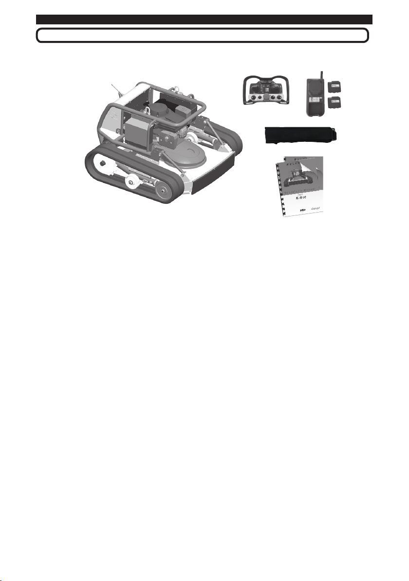
3.1 PACKAGING AND ENDOWMENT
The machine is supply with:
1 x Basic Unit X-Rot
1 x Radio Control
2 x Lithium battery for Radio control
1 x Battery charger
1 x Radio control’s hanging belt
1 x User Manual & Engine user manual
1 x Rod (for crawler replacement)
Before to use the machine, check the fuel and engine’s oil level and read
carefully the instruction manual about the safety regulation and the proce-
dures to start and control the machine.
3.2 PRELIMINARY TESTS
Before to use the machine for the first time, it is necessary to verify:
• Engine oil level (see Cap. 7.1.1)
• Fuel level in the tank (see Cap. 7.1.3)
• Battery charge on the Radio receiver (see Cap. 7.1.5)
- The engine oil should be always on the mark of the upper level. Lack of oil
will decrease the engine performance on the slope.
- The fuel level should be near to the max but not reaching the collar of the
tank. In case of slope the fuel can spill out and create a danger of fire.
- The 2 battery set have to be charged before to start any work. One battery
should be enough for one day operation but the 2nd one is required in case of
need.
Fig 6

I. SAFETY
13
SECTION 4 - COMPONENTS AND CONTROLS
4 - COMPONENTS AND CONTROLS
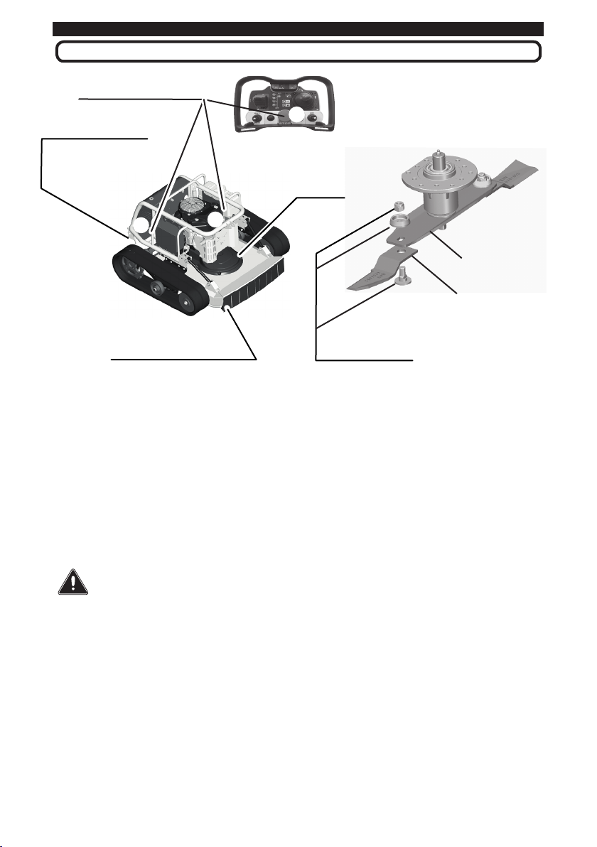
4.1 NAME OF MAJOR COMPONENTS (fig.7)
G
I
M
L
N
E
D
C
BA
O
Q
T
P
U
Basic Unit: Identification of the main components.
A) Tensor wheels H) Battery case & Start key Q)Remote control
B) Crawler’s roller I) Engine - Air inlet R) Front Flap-guard
C) Drive wheel L) Fuel Tank S) Blade support
D) Crawler Belt M) Air filter T) Blade
E) Rear Flap-guard N) Emergency switch U) Blade Fasteners
F) Drive motors O) Belt case
G)Electric cabinet P) Mower deck (*) Safety Parts
Fig 7
H
F
S
R

Tiller B70
14
SECTION 4 - CONTROLS
4.2 ENGINE (fig.7 - I)
The machine is equipped by a high quality petrol engine made in USA and
designed to assure a long operating life. The engine is provided by an electric
start. To start the engine follow the procedure of Cap. 5.2.
The engine is also provided by a forced lubrication system which help to
work in a sloping areas, nevertheless it is highly recommend not to exceed
the 35°. The instruction of the max angle are reported on the bottom of the
radio control.
IMPORTANT
Donotleavethemachineintheslopewiththeenginerunning.The
lubricationcanbeinsufficientandcausetheenginefailure.
ATTENTION
Neverstoptheenginewhilethemachineisontheslope.Theenginestop
willcausetheswitchingoffofthedrivemotors.Forparkingmovethe
machinetoaflatground.
The first 50 working hours represent the run-in of the engine. During this
first period we recommend not to use the machine at the full power.
It is also necessary to leave the engine running for few minutes at the idle
speed for warming after starting. A sudden use at the max power just after
starting cause a thermal shock to the engine components.
4.2.1 AIR FILTER (Fig.7 - M - Fig 27)
The engine is equipped by an air filter. In case of dry grass and dusty
environment the air filter have to be cleaned very often (every 2 hours). If
some flying grass are trapped by the net of engine inlet air (Fig. 7 - I) it means
that probably also the air filter need to be cleaned out. (see cap. 7.1.2). The
clogging of the air filter can cause a lose of engine power. In normal condition,
the air filter should be cleaned every day.
4.2.2 FUEL TANK (Fig.7 - L)
The fuel tank have a capacity of 15 liters of petrol and should assure 6 hours
of operation. Before to start any work remind to fill up the fuel tank. A reserve
of fuel of 3 litres (marked by a pilot light on the radio control) warn that it is
time to refuel. stop working and move the machine in a flat hard soil for refuel-
ling.
DANGER
Payattentionwhilerefuelling:Thegasofpetrolarehighlyexplosive.Do
notattempttorefuelifsomebodyaresmokingorinpresenceofsparksor
openflames.
I. SAFETY
15
SECTION 4 - CONTROLS
4.3 MOWER DECK (fig.7 - p)
The mower deck has a special design to reduce the power required. It is
connected directly to the engine by belt and disconnected by an EM clutch.
The engagement of the Mower is only possible if the engine is running at
suitable speed. (see Cap.5.7). The blade system is made with a strong cutter
for heavy duty operations. The Blade and Blade Fasteners as well as the
flap protection guard are safety components and should be verified
often according to the maintenance schedule 7.2.1. The cutting height
can be adjust from the remote control and it is visible from an indicator on the
right hand side of the machine (see Fig. 8 ). For maintenance of EM Clutch,
Blades and transmission Belt please refer to Cap. 7.2.7.
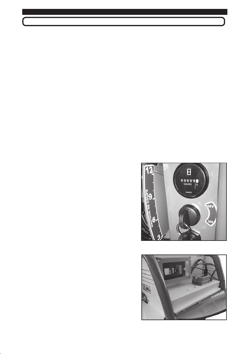
4.4 ELECTRIC SYSTEM
The driving system of this mower is electric. The alternator driven by the
petrol engine generates an electricity supply voltage of 48 V in a range (Extra-
low voltage - ELV) which carries no risk of electrical shock.
The crawler are then driven by 2 brushless electric motors controlled
electronically by 2 inverters with a sophisticate software that makes the
machine easy to use and flexible.
The electric cabinet on the back of the
machine have a easy access to the radio
receiver and to the fuse and relays boxes
(Fig 9). The electric system has a waterproof
grade of IP 54.
4.5 TRANSMISSION
The transmission of the power to the
crawler are made by 2 strong and silent
gear reductors. The portal shape of the
transmission allows to keep very low the
4 - CONTROLS
Fig 8
Fig 9
Fuse Box
Receiver
centre of gravity of the machine which is 15
cm off the ground, only. The technology of
these electric motors grants the maximal
torque also at a standstill. These 2 features
make this machine suitable for working on
very sloping ground. Moreover in case of
electric power failure, a passive breakage
device save the machine from running
downhill without any control.

Tiller B70
16
SECTION 4 - CONTROLS
4.6 REMOTE CONTROL
The remote control is a heavy duty and reliable unit which allow to carry
out all the controls and the adjustment of the machine. It works on a frequency
of 2,4 GHz with the Transmission technology AFA (Automatic Frequency
Adjustment) that automatically shift to a new free channel in case of noise on
the transmission.
CONTROLS OF THE RADIO TRANSMITTER
1 Radio connection button 6 Drive control Forw./Rev. - Left/Right
2 Engine Start button (with (1)) 7 Aux actuator adjustment lever
3 Engine's throttle 8 Drive reference inverter switch
4 PTO Switch button 9 Alarm switch (motorstop)
5 Cutting hight adjustment lever 10 Aux socket switch
Fig 10
56
47
2
8
3
1
10
9

17
SECTION 5 - HOW TO USE THE MACHINE
5 - RULES FOR A SAFE USE
Fig 11-a
ab
c
d
e
f
5.1 CONNECTING THE RADIO CONTROL
Turn the Starting Key switch to ON position. The buzzer
will start to sound to warn that the Radio control is not
connected.
To connect the Radio Control press the Green Button
(1 - Fig.10) on the left hand side of the remote control and
wait until the 2 warning lamps green (a) and blue (b) (see Fig. 11) start to
blink; then push again the green button (1 - Fig.10). The warning lamps stop
blinking and the Buzzer stop to sound : the radio control is now linked .
5.2 ENGINE START(fig.11)
Move the throttle lever up (c -Fig 11) to the maximum.
To start the engine at low temperature, pull the starter
(choke) (for Kawasaki engine only). Push both Buttons
on the left hand side (Fig.10 (1) and (2)) until the
engine starts.
Move the throttle lever down to reach the idle speed
and let the engine warm up. The engine speed will be
displayed by the Leds column (see Fig.11-a)
1700
2200
2700
3200
rpm
rpm
rpm
rpm
Fig 11-b
18
SECTION 5 - HOW TO USE THE MACHINE
5.3 ENGINE STOP (fig. 11)
To stop the engine push anytime the Red
STOP Button (Fig 11 - f) and the engine will
suddenly stops. Just after stopping, remind to
release the emergency Button (f) in its normal
position. After this operation it is necessary
to connect again the Radio control to the
machine.The engine can be also turned OFF
by Alarm Button on the top of the machine (Fig.7
(l)), or just turning the Star Key (Fig 7 (h1)) OFF or if the machine lose the
Radio connection with the remote Control.
NOTE: Ifpossibleitisalwaysrecommendtomovethemachineinaflatground
beforetostoptheengine.IncaseofemergencySTOPassoonaspossible
starttheengineandmovethemachineinsuitableflatgroundforparking.
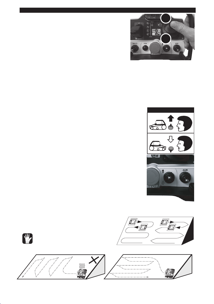
5.4 HOW TO DRIVE (fig.12 and 13)
Check that the lever (8) is set in the UPER position.
Fig 12
F
R
A-A A-B
Fig 13
Fig 14-b
6
8
This lever reverse the motion. Move the Joystick (6)
FORWARD gradually and continuously. The machine
will move ahead. The machine can be easily controlled
by a finger that controls both speed and direction. It
is possible to reverse the Joystick function when the
machine moves forward and towards you (Fig 13).
5.5 HOW TO DRIVE IN A SLOPE
In a slope it is recommend to drive in a longitudinal
way and (if possible) with the left hand side downhill.
To work on the slope it is not necessary to turn (A-A)
because the machine can work in both direction. So the
suggested path is A-B as represent in the Fig 14-a.
It is reccomend to work longitudinally and not up
USE OF INVERSING SWITCH
OK !
Slow....
Fast.....
and down (Fig 14 -b). In this 2nd case the
machine will drive much slower and the
transmission will warm up.
ATTENTION
Donotexcedethe45°whendrive
longitudinallyandthe20°when
drivedownhill. Fig 14-a
Table of contents
Other BHV Lawn Mower manuals


