Biber OSKA9563 User manual

SB-520-1
Open screw compressors for NH3 applications
Translation of the original Operating Instructions
English....................................................................................................................................................... 2
Offene Schraubenverdichter für NH3-Anwendungen
Originalbetriebsanleitung
Deutsch ..................................................................................................................................................... 16
Compresseurs à vis ouverts pour applications NH3
Traduction des instructions de service d'origine
Français..................................................................................................................................................... 30
OSKA9563
OSKA9583
OSKA9593
OSKA95103
OSNA9563
OSNA9583
OSNA9593
OSNA95103
Installer
Monteur
Monteur

SB-520-12
Table of contents
1 Introduction............................................................................................................................................................4
1.1 Also observe the following technical documents ...........................................................................................4
2 Safety ....................................................................................................................................................................4
2.1 Authorized staff..............................................................................................................................................4
2.2 Residual hazards...........................................................................................................................................4
2.3 Safety references...........................................................................................................................................4
2.3.1 General safety references ................................................................................................................. 4
3 Application ranges.................................................................................................................................................5
4 Mounting................................................................................................................................................................5
4.1 Transporting the compressor.........................................................................................................................5
4.2 Installing the compressor...............................................................................................................................5
4.3 Direct drive via coupling.................................................................................................................................5
4.4 Connecting the pipelines ...............................................................................................................................6
4.4.1 Pipe connections................................................................................................................................ 6
4.4.2 Pipelines ............................................................................................................................................ 6
4.4.3 OSKAB (booster version)................................................................................................................... 7
4.5 Connections and dimensional drawing..........................................................................................................8
4.5.1 Additional connections for evacuation ............................................................................................... 9
4.5.2 Capacity control and start unloading.................................................................................................. 9
5 Electrical connection..............................................................................................................................................9
5.1 Mains connections.........................................................................................................................................9
5.2 Safety and protection devices........................................................................................................................9
5.2.1 Compressor control module............................................................................................................... 9
5.2.2 Motor safety and protection devices .................................................................................................. 9
5.2.3 High pressure switches.................................................................................................................... 10
6 Commissioning ....................................................................................................................................................10
6.1 Checking the strength pressure...................................................................................................................10
6.2 Checking tightness ......................................................................................................................................10
6.3 Charging with oil ..........................................................................................................................................10
6.4 Evacuation...................................................................................................................................................10
6.5 Charging with refrigerant .............................................................................................................................11
6.6 Tests prior to compressor start....................................................................................................................11
6.7 Compressor start .........................................................................................................................................11
6.7.1 Checking the rotation direction ........................................................................................................ 11
6.7.2 Start ................................................................................................................................................. 11
6.7.3 Checking the oil level ....................................................................................................................... 11
6.7.4 Setting high pressure and low pressure switches (HP + LP)........................................................... 12
6.7.5 Setting the condenser pressure control ........................................................................................... 12
6.7.6 Checking the operating data ............................................................................................................ 12
6.7.7 Vibrations ......................................................................................................................................... 12
6.7.8 Particular notes on safe compressor and system operation ............................................................ 12
7 Operation.............................................................................................................................................................13
7.1 Regular tests................................................................................................................................................13

SB-520-1 3
8 Maintenance........................................................................................................................................................13
8.1 Integrated pressure relief valve ...................................................................................................................13
8.2 Integrated check valve.................................................................................................................................13
8.3 Oil filter.........................................................................................................................................................13
8.4 Oil change....................................................................................................................................................13
8.5 Shaft seal.....................................................................................................................................................13
8.6 Coupling.......................................................................................................................................................14
8.6.1 Elastomer elements ......................................................................................................................... 14
8.6.2 Checking the elastomer elements for wear...................................................................................... 14
8.7 Roller bearings.............................................................................................................................................14
8.7.1 Checking the roller bearings ............................................................................................................ 14
8.7.2 Replacement of the roller bearings .................................................................................................. 14
9 Decommissioning ................................................................................................................................................14
9.1 Standstill ......................................................................................................................................................14
9.2 Dismounting the compressor.......................................................................................................................15
9.3 Disposing of the compressor .......................................................................................................................15
9.4 Dismounting the oil separator and oil cooler................................................................................................15

SB-520-14
1 Introduction
These refrigeration compressors are intended for incor-
poration into refrigeration systems in accordance with
the 2006/42/EC Machinery Directive. They may only be
put into operation if they have been installed in the refri-
geration systems according to these Mounting/Operat-
ing Instructions and if the overall system complies with
the applicable legal provisions (applied standards: see
declaration of incorporation).
The compressors have been built in accordance with
state-of-the-art methods and current regulations. Partic-
ular importance was placed on user safety.
These Operating Instructions must be kept available
near the refrigeration system during the whole lifetime
of the compressor.
1.1 Also observe the following technical documents
SW-100: Tightening torques for screw fixings.
ST-150: Compressor monitoring module CM-SW-01.
2 Safety
2.1 Authorized staff
All work done on compressors and refrigeration sys-
tems may only be performed by qualified and author-
ized staff who have been trained and instructed accord-
ingly. The qualification and expert knowledge of the
personnel must correspond to the local regulations and
guidelines.
2.2 Residual hazards
The compressor may present unavoidable residual
risks. That is why any person working on this device
must carefully read these Operating Instructions.
The following rules and regulations are mandatory:
• the relevant safety regulations and standards (e.g.
EN 378-2, EN 60204, EN 60335 and EN953),
• generally accepted safety rules,
• EU directives,
• national regulations.
2.3 Safety references
are instructions intended to prevent hazards. Safety ref-
erences must be stringently observed!
!
!
NOTICE
Safety reference to avoid situations which may
result in damage to a device or its equipment.
CAUTION
Safety reference to avoid a potentially hazard-
ous situation which may result in minor or mod-
erate injury.
WARNING
Safety reference to avoid a potentially hazard-
ous situation which could result in death or seri-
ous injury.
DANGER
Safety reference to avoid an imminently hazard-
ous situation which may result in death or seri-
ous injury.
2.3.1 General safety references
State of delivery
CAUTION
The compressor is filled with a holding charge:
Overpressure 0.5 .. 1 bar.
Risk of injury to skin and eyes.
Depressurize the compressor!
Wear safety goggles!
For work on the compressor once it has been
commissioned
DANGER
Hair, hands or clothes may get caught in the
coupling!
Serious injuries are possible.
Secure the coupling zone with a separating
cover (protective grid)!
CAUTION
Surface temperatures of more than 60°C or be-
low 0°C.
Risk of burns or frostbite.
Close off accessible areas and mark them.
Before performing any work on the compressor:
switch it off and let it cool down.
SB-520-1 5
!
!
NOTICE
Risk of compressor failure!
Operate the compressor only in the intended ro-
tation direction!
WARNING
The compressor is under pressure!
Serious injuries are possible.
Depressurize the compressor!
Wear safety goggles!
3 Application ranges
Allowed refrigerant: R717 (NH3)
Oil charge: Reniso KC68, Reflo 68A, SHC226E
Application limits: See brochure SP-520 and
BITZER SOFTWARE
Risk of air penetration during operation in the vacuum
range
!
!
NOTICE
Potential chemical reactions as well as in-
creased condensing pressure and rise in dis-
charge gas temperature.
Avoid air penetration!
WARNING
A critical shift of the refrigerant ignition limit is
possible.
Avoid air penetration!
4 Mounting
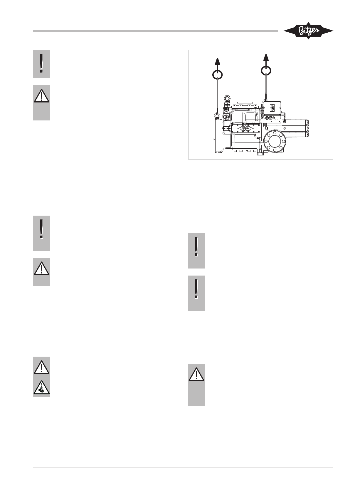
4.1 Transporting the compressor
Either transport the compressor screwed onto the pallet
or lift it using the eyebolts, see figure 1, page 5.
DANGER
Suspended load!
Do not step under the machine!
Fig.1: Lifting the compressor
4.2 Installing the compressor
Install/mount the compressor horizontally. Take suit-
able measures if the compressor is operated under ex-
treme conditions (e.g. aggressive atmosphere, low out-
door temperatures, etc.). Consultation with BITZER is
recommended.
!
!
NOTICE
Do not mount the compressor solidly on the
heat exchanger!
Risk of damage to the heat exchanger (fatigue
fractures).
!
!
NOTICE
Potential chemical reactions due to air penetra-
tion!
Proceed swiftly and keep shut-off valves closed
until evacuation.
Provide sufficient free space under the suction gas filter
housing for dismounting and mounting the suction gas
filter (>450mm).
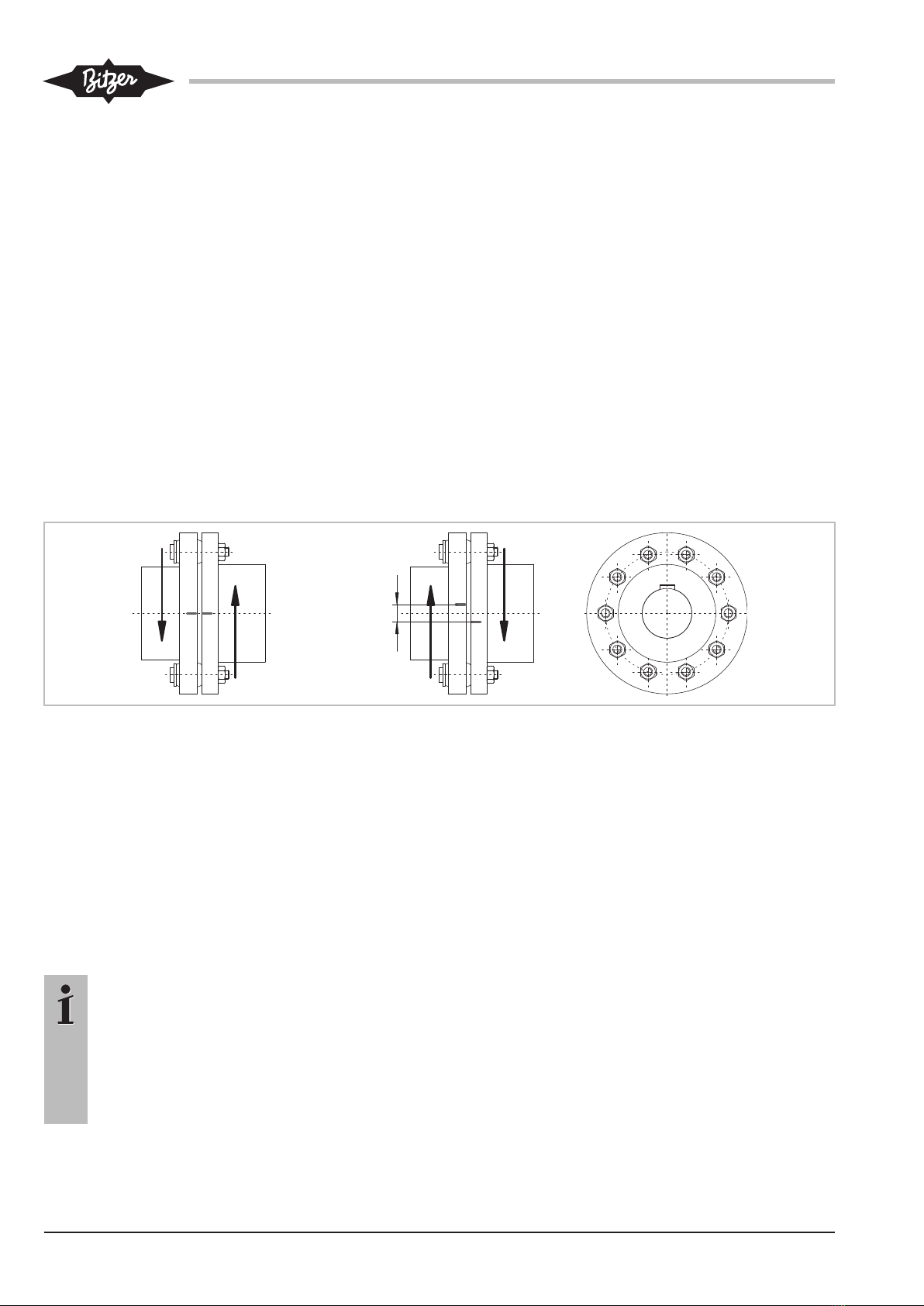
4.3 Direct drive via coupling
DANGER
Hair, hands or clothes may get caught in the
coupling!
Serious injuries are possible.
Secure the coupling zone with a separating
cover (protective grid)!
SB-520-16
Information
Observe safety standards EN ISO 13857 / EN
294 / EN 349 and national regulations.
Use only couplings with elastic intermediate ele-
ments which can compensate for slight shifts in
axial direction, but do not exert their own axial
force.
!
!
NOTICE
Risk of damage to the compressor due to wrong
couplings!
Use only couplings approved by BITZER!
Approved coupling:
• KS900
The compressor is connected to the motor via the
coupling housing:
• Clean mating surfaces on the compressor, motor
and coupling housing.
• Install the motor on rails.
• Slide the coupling half for the compressor side (in-
cluding parallel key) on the compressor shaft, make
sure that it is flush and fasten it with screws, fasten
the compressor to the coupling housing.
• Slide the coupling half for the motor side (including
parallel key) loosely on the motor shaft, fasten the
coupling housing to the motor.
• Remove protective grid from the coupling housing,
move the coupling half on the motor side until the
clearance is 2 .. 5 mm, then fasten it with screws.
• Make sure to re-install the protective grid afterwards!
!
!
NOTICE
Poor coupling alignment may cause premature
coupling failure and damage to bearings and
shaft seal!
Carefully align the motor and compressor shaft!
!
!
NOTICE
Risk of damage to compressor and coupling!
Firmly tighten the fixing elements of both coup-
ling halves to prevent them from getting loose
during operation!
Tightening torque: 15Nm.
Provide additional support for the compressor on the
base frame.
Direct drive without coupling housing is possible, but it
requires a very stable base frame and an exact align-
ment of the compressor shaft and motor shaft. The
shaft ends must not touch each other. For height ad-
justment, use stable supports (flat sheets).
Special drives (e.g. combustion engines) require indi-
vidual consultation with BITZER.
4.4 Connecting the pipelines
WARNING
The compressor is under pressure!
Serious injuries are possible.
Depressurize the compressor!
Wear safety goggles!
!
!
NOTICE
Potential chemical reactions due to air penetra-
tion!
Proceed swiftly and keep shut-off valves closed
until evacuation.
4.4.1 Pipe connections
The pipe connections are designed in way that they are
suitable for pipes in all common dimensions in milli-
metres and inches.
!
!
NOTICE
Do not overheat the shut-off valves!
Cool the valve body and the welding adapter
during and after the welding operation.
For welding, dismount the pipe connections and
the bushes.
4.4.2 Pipelines
Use only pipelines and system components which are
clean and dry inside (free from slag, swarf, rust and
phosphate coatings) and which are provided with an
air-tight seal on delivery.
As standard, the compressors are supplied with blank-
ing plates on the pipe connections. These must be re-
moved before performing the strength pressure and
tightness tests and commissioning the system.
!
!
NOTICE
For systems with rather long pipelines or for
welding operations without protective gas:
Install the suction-side cleaning filter (mesh size
<25μm).
Information
The blanking plates are only designed to serve
as a transport protection. They are not suitable
as a separation between different system sec-
tions during the strength pressure test.

SB-520-1 7
!
!
NOTICE
Risk of compressor damage!
Evacuate the system and flush it once or sev-
eral times with dry nitrogen, if necessary.
Mount pipelines in such a way that the compressor is
protected from flooding with oil or liquid refrigerant dur-
ing standstill. Strictly observe the instructions indicated
in the manual SH-510.
Lines for economiser (ECO) and liquid injection (LI):
The ECO connection is arranged on the top side of the
compressor housing, therefore a bridge for protection
against oil migration is not required. Guide the line hori-
zontally or downwards from the connection. See Tech-
nical Information ST-600.
When retrofitting the ECOshut-off valve:
Information
To increase the corrosion protection, it is recom-
mended to paint the ECO shut-off valve.
4.4.3 OSKAB (booster version)
An external oil pump may be necessary in systems
where a sufficient oil pressure difference cannot be
built up directly after the compressor start. This may
apply, for example, to large parallel compounding sys-
tems with extremely low condensing temperature or to
boosters.

SB-520-18
4.5 Connections and dimensional drawing
1a (HP)
1/8-27 NPTF
3 (HP)
1/8-27 NPTF
7a
M22x1,5
1/8-27 NPTFG 1/4
2b (LP) 2a (LP)
1/8-27 NPTF
Ø21
Ø12
1/8-27 NPTFG 1/4
1b (HP)
19 5
20
Vi (–)Vi (+)
17
M22x1,5
Ø332
Ø370
M16
Ø65
94
SL
466
170
55
450
822
217
599
632
664
458
356
535
1055
155
315 580
30
117
332
198
206
DL
41 (HP)2 (LP)
161
12°
Ø294
Ø288
17
7b
1/8-27 NPTF
CR (–) CR (+)
18
187
1/8-27 NPTF
50
94
611
206
44
7c
14
Fig.2: Dimensional drawing OS.A95103
Connection positions
1 High pressure connection (HP)
1a Additional high pressure connection (HP)
1b Connection for high pressure transmitter
(HP)
2 Low pressure connection (LP)
2a Additional low pressure connection (LP)
2b Connection for low pressure transmitter
(LP)
3 Connection for discharge gas temperature
sensor (HP)
4 Connection for economiser (ECO) or liquid
injection (LI)
HS.85 and OS.85: Connection for econo-
miser (ECO)
Connection positions
HS.85: ECO valve with connection line
(option)
OS.85 and OS.95: ECO valve (option)
5 Connection/valve for oil injection
6 Oil pressure connection
HS.85 and OS.85: Oil drain (compressor
housing)
7 Oil drain (motor housing)
7a Oil drain (suction gas filter)
7b Oil drain from shaft seal (maintenance con-
nection)
7c Oil drain hose (shaft seal)
8 Threaded bore for foot mounting

SB-520-1 9
Connection positions
9 Threaded bore for pipe fixture (ECO and LI
lines)
10 Maintenance connection for oil filter
11 Oil drain (oil filter)
12 Monitoring of oil stop valve
OS.85: Monitoring of rotation direction and
oil stop valve
13 Oil filter monitoring
14 Oil flow switch
OS.95: Oil level monitoring
15 Earth screw for housing
16 Oil drain (oil filter chamber)
17 Maintenance connection for shaft seal
18 Liquid injection (LI)
19 Compressor monitoring module
(CM-SW-01)
20 Slider position indicator
SL Suction gas line
DL Discharge gas line
Tab.1: Connection positions
Dimensions (if specified) may have tolerances accord-
ing to ENISO13920-B.
The legend applies to all open and semi-hermetic
BITZER screw compressors and contains connection
positions that do not occur in every compressor series.
4.5.1 Additional connections for evacuation
In case of a great system volume, install generously
sized, lockable additional connections on the pressure
and suction side. Sections locked by check valves must
have separate connections.
4.5.2 Capacity control and start unloading
The OS.A95 compressors are equipped with an "infinite
capacity control" (slide control). The compressor control
module controls the solenoid valves.
For the detailed descriptions of the capacity control,
see Technical Information ST-150.
For the start unloading, the compressor control module
sets the capacity slider to the minimum displacement.
For this, a time period of approx. 5 min in the system
control must be provided.
5 Electrical connection
!
!
NOTICE
Risk of short-circuit due to condensation water
in the terminal box!
Use only standardised cable bushings.
When mounting, pay attention to proper sealing.
General information
Compressors and electrical equipment comply with the
EU Low Voltage Directives 2006/95/EC and 2014/35/
EU.
Connect mains cables, protective earth conductors and
other cables according to the description, see Tech-
nical Information ST-150. Observe the safety standards
EN60204, IEC60364 and national safety regulations.
5.1 Mains connections
When dimensioning motor contactors, feed lines and
fuses:
• Use the maximum operating current or maximum
power consumption of the motor as a basis.
• Select the contacts according to the operational cat-
egory AC3.
Compare the voltage and frequency specifications on
the motor type plate with the data of the mains supply.
The motor may be connected only if the values match.
Wire the terminals according to the instructions of the
motor manufacturer.
!
!
NOTICE
Risk of compressor failure!
Operate the compressor only in the intended ro-
tation direction!
5.2 Safety and protection devices
5.2.1 Compressor control module
The compressor control module monitors the essential
operating parameters and protects the compressor
from operation under critical conditions, see Technical
Information ST-150.
5.2.2 Motor safety and protection devices
Provide motor safety and protection devices according
to the regulations of the motor manufacturer or the dir-
ectives on the protection of drive motors.
SB-520-110
5.2.3 High pressure switches
A pressure limiter and a safety pressure limiter are re-
quired for securing the compressor's application range
in order to avoid unacceptable operating conditions.
The low pressure can be secured using the built-in low
pressure transmitter, see Technical Information
ST-150.
6 Commissioning
The compressor has been carefully dried, checked for
tightness and filled with a holding charge (N2) before
leaving the factory.
DANGER
Risk of explosion!
Never pressurize the compressor with oxygen
(O2) or other industrial gases!
WARNING
Risk of bursting!
A critical shift of the refrigerant ignition limit is
possible in case of excess pressure.
Do not add a refrigerant (e.g. as a leak indic-
ator) to the test gas (N2 or air).
Environmental pollution in case of leakage and
when deflating!
!
!
NOTICE
Risk of oil oxidation!
Check the entire system for strength pressure
and tightness, preferably using dried nitrogen
(N2).
When using dried air: Remove the compressor
from the circuit – make sure to keep the shut-off
valves closed.
6.1 Checking the strength pressure
Check the refrigerant circuit (assembly) according to
EN378-2 (or other applicable equivalent safety stand-
ards). The compressor had been already tested in the
factory for strength pressure. A tightness test is there-
fore sufficient, see chapter Checking tightness, page
10.
If you still wish to perform a strength pressure test for
the entire assembly:
DANGER
Risk of bursting due to excessive pressure!
The pressure applied during the test must never
exceed the maximum permitted values!
Test pressure: 1.1-fold of the maximum allow-
able pressure (see name plate). Make a distinc-
tion between the high-pressure and low-pres-
sure sides!
6.2 Checking tightness
Check the refrigerant circuit (assembly) for tightness,
as a whole or in parts, according to EN378-2 (or other
applicable equivalent safety standards). For this, create
an overpressure, preferably using dried nitrogen.
Observe test pressures and safety reference, see
chapter Checking the strength pressure, page 10.
6.3 Charging with oil
Oil type: see chapter Application ranges, page 5. Ob-
serve information in manual SH-510.
Charged quantity: Quantity required for the operation of
oil separator and oil cooler plus the volume of the oil
lines. The additional quantity for oil circulation in the re-
frigerant circuit is approx. 1 .. 2% of the refrigerant
charge; in systems with flooded evaporators the share
of the additional quantity may be greater.
To prevent dry running of the shaft seal during the com-
pressor start, charge approx. 1l oil in the connection
for oil injection (see figure 2, page 8, pos. 5).
Before evacuation, charge oil directly in oil separator
and oil cooler. Open shut-off valves of oil separator / oil
cooler. The filling level in the oil separator must be
within the sight glass area.
Information
The compressor control module controls the
solenoid valve in the oil injection line, see Tech-
nical Information ST-150.
6.4 Evacuation
Switch on oil heater in the oil separator.
Open the shut-off valves. Keep the shut-off valve in the
oil injection line closed. Use a vacuum pump to evacu-
ate the entire system, including the compressor, on the
low and the high pressure sides. With the vacuum
pump shut off, a "standing vacuum" lower than
1.5mbar must be achieved. Repeat the operation sev-
eral times if necessary. After the evacuation, open the
shut-off valve in the oil injection line.

SB-520-1 11
6.5 Charging with refrigerant
DANGER
Risk of bursting of components and pipelines
due to hydraulic excess pressure while feeding
liquid.
Serious injuries are possible.
Avoid overcharging the system with refrigerant
under all circumstances!
!
!
NOTICE
Risk of wet operation during liquid feeding!
Measure out extremely precise quantities!
Maintain the discharge gas temperature well
above the condensing temperature:
with NH3 at least 30K.
!
!
NOTICE
Lack of refrigerant causes low suction pressure
and superheat condition!
Observe the application limits.
• Before charging with refrigerant:
– Use approved refrigerants only (see chapter Ap-
plication ranges, page 5).
– Switch on the oil heater.
– Check the oil level in the oil separator.
– Do not switch on the compressor!
• Charge condenser or receiver, on systems with
flooded evaporator, also the evaporator or liquid sep-
arator directly with liquid refrigerant.
• After commissioning, it may be necessary to add re-
frigerant: While the compressor is running, charge
with refrigerant on the suction side, preferably at the
evaporator inlet or in the liquid separator.
6.6 Tests prior to compressor start
• Oil level in the oil separator (in the sight glass area).
• Oil temperature in the oil separator (approx. 15 ..
20K above ambient temperature).
• Setting and functions of safety and protection
devices.
• Setpoints of the time relays.
• Cut-out pressure values of the high-pressure and
low-pressure limiters.
• Cut-out pressure values of the pressure switches.
Record the setting.
• Are shut-off valves in the oil injection line open?
!
!
NOTICE
Do not start the compressor if it was flooded
with oil due to faulty operation! It is absolutely
necessary to empty it!
Internal components may be damaged.
Close shut-off valves, depressurize the com-
pressor and drain oil via drain plug on the com-
pressor.
6.7 Compressor start
6.7.1 Checking the rotation direction
!
!
NOTICE
Risk of compressor failure!
Operate the compressor only in the intended ro-
tation direction!
Check the rotation direction during the first compressor
start:
• Connect the pressure gauge to the suction shut-off
valve. Close the valve spindle and open again by
one turn.
• Let the compressor start for a short time (approx.
0.5 .. 1 s).
• Correct rotation direction: Suction pressure drops im-
mediately.
• Incorrect rotation direction: Suction pressure in-
creases.
Reverse the polarity of the terminals on the common
feed line.
6.7.2 Start
Restart, slowly open the suction shut-off valve and ob-
serve the sight glass in the oil injection line. If there is
no oil flow within 5 s, switch off immediately. Check oil
supply!
6.7.3 Checking the oil level
Immediately after commissioning, carry out the follow-
ing checks:
• During operation, the maximum and recommended
oil level is within the sight glass area of the oil separ-
ator (the minimum oil level is secured by the oil level
switch).
• During the start phase, oil foam may appear which,
however, should decrease after 2 to 3min. Other-
wise high proportions of liquid in the suction gas are
suspected.

SB-520-112
!
!
NOTICE
Risk of wet operation during liquid feeding!
Measure out extremely precise quantities!
Maintain the discharge gas temperature well
above the condensing temperature:
with NH3 at least 30K.
If the oil level switch is triggered during the start phase
of the oil monitoring system or after the delay time has
elapsed (10 s), this indicates an acute lack of oil. This
may be caused by a too large share of refrigerant in the
oil. Check the suction gas superheat.
!
!
NOTICE
Risk of compressor failure due to liquid slug-
ging!
Before adding larger quantities of oil: check the
oil return!
6.7.4 Setting high pressure and low pressure
switches (HP + LP)
Perform a test to check the exact cut-in and cut-out
pressure values according to the application limits.
6.7.5 Setting the condenser pressure control
Set the condenser pressure so that the minimum pres-
sure difference is reached within 20s after the start (for
application limits, see BITZER SOFTWARE). Avoid
quick pressure reduction with finely stepped pressure
control.
6.7.6 Checking the operating data
• Evaporation temperature
• Suction gas temperature
• Condensing temperature
• Discharge gas temperature:
– Min. 30K (NH3) above condensing temperature
– Max. 100°C
• Oil temperature:
– Reniso KC68, Reflo 68A, SHC226E: max. 60°C
• Cycling rate
• Motor current
• Motor voltage
• For operation with ECO:
– ECO pressure
– Temperature at the ECO connection
• Creation of data protocol
For application limits, see brochure SP-520 or
BITZER SOFTWARE.
To prevent motor failures, the following requirements
are specified:
• Maximum cycling rate, motor current, motor voltage:
Observe the notes of the motor manufacturer.
• Desirable minimum running time: 5 min
!
!
NOTICE
Risk of motor failure!
The specified requirements must be ensured by
the control logic!
6.7.7 Vibrations
When operating with frequency inverter, check the en-
tire speed range of the system for abnormal vibration.
Speeds at which resonances still occur must be
avoided in the programming of the frequency inverter. If
required, take additional safety measures.
!
!
NOTICE
Risk of burst pipes and leakages on the com-
pressor and system components!
Avoid strong vibrations!
6.7.8 Particular notes on safe compressor and
system operation
Analysis show that compressor failures are most often
due to an inadmissible operating mode. This applies
especially to damage resulting from lack of lubrication:
• Always maintain oil heater operation in the oil separ-
ator when the system is at standstill. This is valid for
all applications.
When installing the system in zones where the tem-
peratures are low, it may be necessary to insulate
the oil separator. At compressor start, the oil temper-
ature, that is measured under the oil sight glass,
should be 15 .. 20 K above the ambient temperature.
• Automatic sequence change for systems with sev-
eral refrigerating circuits (approximately every 2
hours).
• Install an additional check valve in the discharge gas
line behind the oil separator if temperature and pres-
sure compensation is not reached even after long
standstill times.
• If needed, mount a time and pressure-dependant
controlled pump down system – particularly for high
refrigerant charges and/or when the evaporator may
SB-520-1 13
become hotter than the suction gas line or the com-
pressor.
For further information about pipe layout, see manual
SH-510.
7 Operation
7.1 Regular tests
Examine the system at regular intervals according to
national regulations.
• Operating data, see chapter Checking the operating
data, page 12.
• Oil supply, see chapter Checking the operating data,
page 12.
• Safety and protection devices and all components
for compressor monitoring, see chapter Safety and
protection devices, page 9 and see chapter Check-
ing the operating data, page 12.
• Tightness of the integrated check valve.
•Check the elastomer elements of the coupling after
the running-in period and then once a year.
• Tight seat of electrical cable connections and
screwed joints.
• Screw tightening torques (see SW-100).
• Refrigerant charge.
• Tightness
• Prepare data protocol.
8 Maintenance
DANGER
Hair, hands or clothes may get caught in the
coupling!
Serious injuries are possible.
Secure the coupling zone with a separating
cover (protective grid)!
WARNING
The compressor is under pressure!
Serious injuries are possible.
Depressurize the compressor!
Wear safety goggles!
8.1 Integrated pressure relief valve
The valve is maintenance-free.
However, after repeated venting, it may leak perman-
ently because of abnormal operating conditions. The
consequences are reduced performance and a higher
discharge gas temperature.
Recommended replacing interval: 100,000h.
8.2 Integrated check valve
If the check valve is defective or contaminated, the
compressor runs for some time in reverse direction
after it has been switched off. The valve must then be
changed.
Recommended replacing interval: 20,000 .. 40,000h.
8.3 Oil filter
It is recommended to change the oil filter for the first
time after 50 .. 100 operating hours. During operation,
the degree of contamination can be permanently
checked by the oil filter monitoring (option).
8.4 Oil change
The listed oils (see chapter Application ranges, page 5)
are characterised by a particularly high degree of stabil-
ity. With NH3 operation, it is recommended to change
oil once a year or after each 5,000 operating hours.
Impurities stemming from the plant components or op-
erating outside the application ranges are the only
things that can cause deposits to form in the lubricating
oil, causing it to darken. In this case, change the oil.
Also renew the oil filter. Determine the cause of operat-
ing outside of the application area and eliminate it.
Oil types: see chapter Application ranges, page 5.
WARNING
Oil separator and oil cooler are under pressure!
Serious injuries are possible.
Depressurize oil separator and oil cooler!
Wear safety goggles!
Dispose of waste oil properly!
8.5 Shaft seal
A routine check of the shaft seal is generally not re-
quired.
However, with regard to the operational reliability, a
check in connection with oil change or faults in the lub-
ricating circuit is recommended.
In doing so, pay particular attention to:
• hardening and cracks on the O-rings
SB-520-114
• wear
• corrugations
• material deposits
• oil carbon
• copper plating
Leakage oil quantities up to approx. 0.2cm3 per operat-
ing hour are within the tolerance range. Leakage oil
which may escape can be drained via an oil drain pipe
at the flange of the shaft seal.
Increased oil leakage is possible during the running-in
period of the shaft seal (approx. 250 hours).
Recommended replacing interval: 20,000 .. 40,000h.
8.6 Coupling
8.6.1 Elastomer elements
Check the elastomer elements of the coupling after the
running-in period and then once a year, see figure 3,
page 14.
8.6.2 Checking the elastomer elements for wear
• Turn both coupling halves without torque against
each other to the stop.
• Mark both halves.
• Turn coupling halves also without torque to the other
direction to the stop.
• Measure radial distance between the two marks.
• Replace all elastomer elements if the distance is
more than 4mm.
ma x . 4 m m
Fig.3: Checking the elastomer elements of the coupling
8.7 Roller bearings
BITZER screw compressors are equipped with durable
roller bearings. Therefore, a replacement is generally
not required.
8.7.1 Checking the roller bearings
The roller bearings are checked by means of the noise
analysis.
Recommended test interval: 10,000h.
Information
When replacing the roller bearings, visually
check the rotors, the housing and the discharge
flange.
In case of deep corrugations or abnormal wear,
a general overhaul of the compressor by
BITZER or Green Point or its replacement is re-
commended.
8.7.2 Replacement of the roller bearings
Recommended replacing interval: 40,000 .. 50,000h.
In this case, the entire service life of the roller bearings
is not used.
The bearings may need to be replaced due to occa-
sional deviations from the standard operation, such as
lack of oil, wet operation or thermal overload.
9 Decommissioning
9.1 Standstill
Leave the oil heater switched on until disassembly.
This prevents increased refrigerant concentration in the
oil.
SB-520-1 15
9.2 Dismounting the compressor
WARNING
The compressor is under pressure!
Serious injuries are possible.
Depressurize the compressor!
Wear safety goggles!
In the case of repair work requiring dismounting or in
the event of decommissioning:
Close the shut-off valves on the compressor. Extract
the refrigerant. Do not deflate the refrigerant, but dis-
pose of it properly!
Open screwed joints or flanges on the compressor
valves. Remove the compressor using hoisting equip-
ment.
9.3 Disposing of the compressor
Drain the oil from the compressor. Dispose of waste oil
properly!
Have the compressor repaired or dispose of it properly.
9.4 Dismounting the oil separator and oil cooler
WARNING
Oil separator and oil cooler are under pressure!
Serious injuries are possible.
Depressurize oil separator and oil cooler!
Wear safety goggles!
Drain oil when performing repair work or decommis-
sioning the oil separator and oil cooler.
If possible, block refrigerant and oil lines in front of and
behind the oil separator and oil cooler.
Prepare a pan: Drain oil, collect oil and dispose of it
properly.
In case of damage, the oil separator or oil cooler must
be separated from the refrigerator system and re-
placed. For this, extract the refrigerant and drain the
coolant.
Dispose of contaminated substances properly!

BITZER Kühlmaschinenbau GmbH
Eschenbrünnlestraße 15 // 71065 Sindelfingen // Germany
Tel +49 (0)70 31 932-0 // Fax +49 (0)70 31 932-147
[email protected] // www.bitzer.de
Subject to change // Änderungen vorbehalten // Toutes modifications réservées // 80450801 // 02.2017
80450801 // 02.2017
Subject to change
Änderungen vorbehalten
Toutes modifications réservées
This manual suits for next models
7
Table of contents
Popular Air Compressor manuals by other brands

California Air Tools
California Air Tools 8010SPC owner's manual

Craftsman
Craftsman 16923 owner's manual

Emerson
Emerson Copeland Discus Series Application guidelines

GEA
GEA FK40/560 N Assembly instructions

BLACKMER
BLACKMER NGH1013 Installation, operation and maintenance instructions

BUSCH
BUSCH Mink MM 1202 AP Installation and operating instructions


