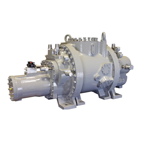
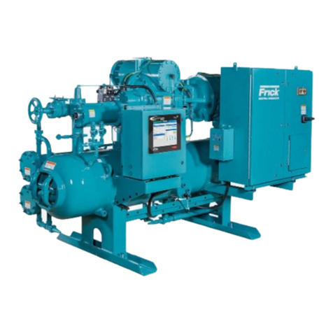
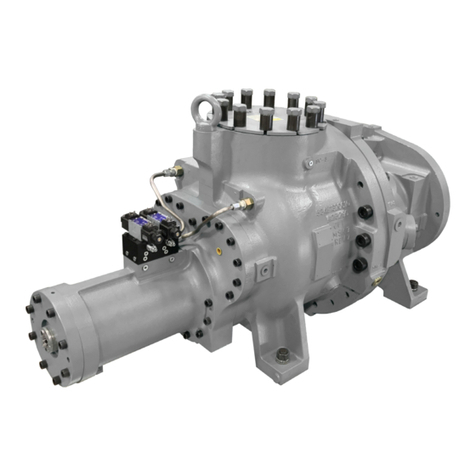
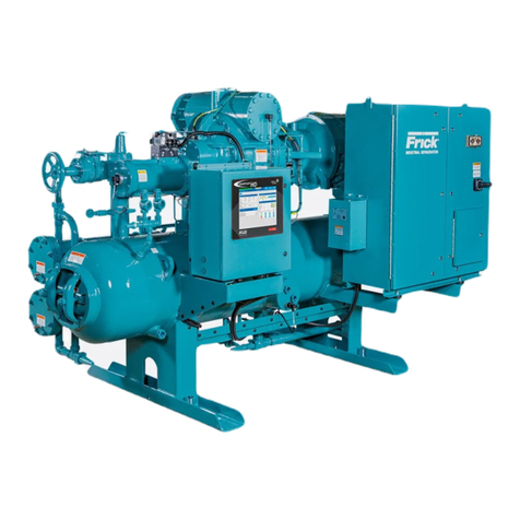
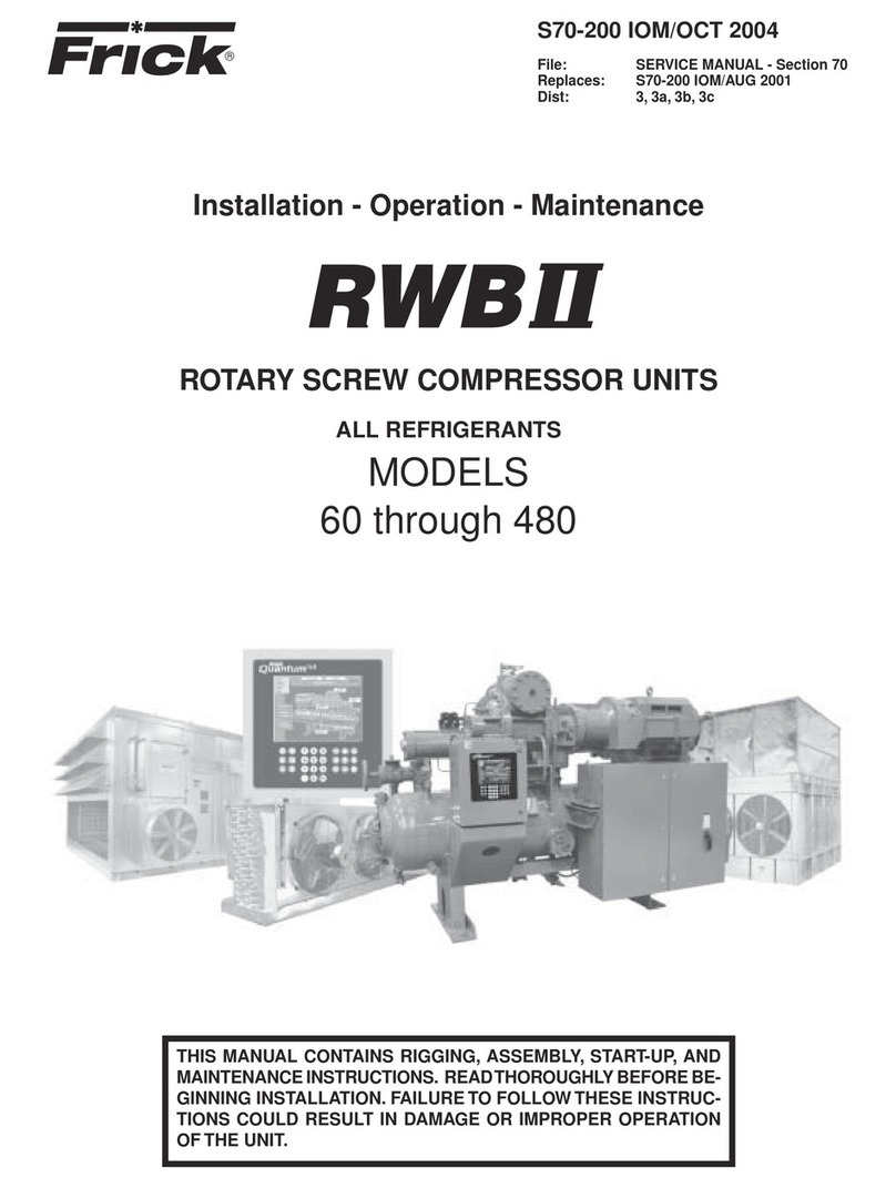
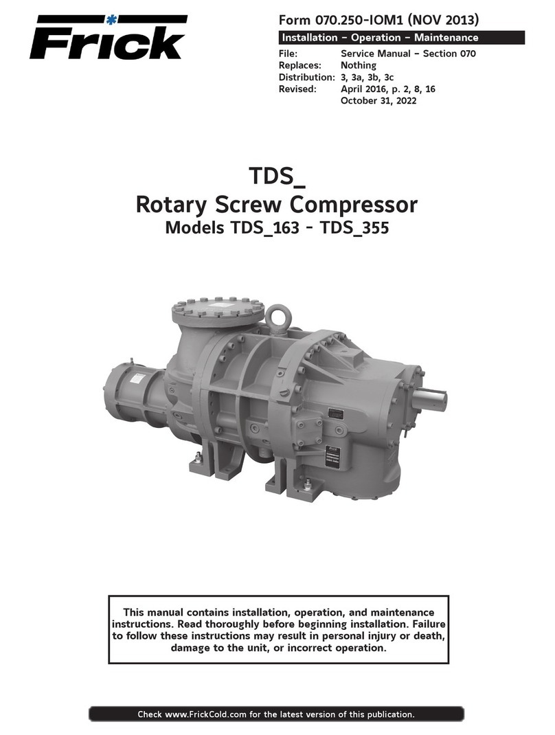
Frick RXB PLUS Owner's manual

Installation - Operation - Maintenance
ROTARY SCREW COMPRESSOR UNITS
WITH
MICROPROCESSOR CONTROL
ALL REFRIGERANTS
THIS MANUAL CONTAINS RIGGING, ASSEMBLY, START-UP, AND
MAINTENANCE INSTRUCTIONS. READ THOROUGHLY BEFORE
BEGINNING INSTALLATION. FAILURE TO FOLLOW THESE IN-
STRUCTIONS COULD RESULT IN DAMAGE OR IMPROPER OPERA-
TION OF THE UNIT.
S70-101 IOM/JAN 2000
File: SERVICE MANUAL - Section 70
Replaces: S70-101 IOM/APR 96
Dist: 3, 3a, 3b, 3c

RXB PLUS ROTARY SCREW COMPRESSOR UNITSS70-101 IOM
Page 2 INSTALLATION - OPERATION - MAINTENANCE
GENERAL INFORMATION
Preface..............................................................................3
Design Limitations ............................................................3
Job Inspection...................................................................3
Transit Damage Claims .....................................................3
Compressor/Unit Identification..........................................3
INSTALLATION
Foundation ........................................................................4
Handling and Moving ........................................................4
Skid Removal ....................................................................5
Motor Mounting .................................................................5
Compressor/Motor Coupling Installation ..........................5
Coupling Alignment Procedure .........................................6
Hot Alignment of Compressor/Motor ................................8
Checking Motor/Compressor Rotation..............................8
Holding Charge and Storage ............................................8
Compressor Oil .................................................................8
Oil Charge.........................................................................8
Oil Heater..........................................................................8
Liquid Injection Oil Cooling ...............................................9
Dual Dip Tube Method.......................................................9
Level Control Method........................................................9
Water-Cooled Oil Cooling ...............................................10
Thermosyphon Oil Cooling .............................................10
Economizer - High Stage ................................................12
Electrical .........................................................................13
Motor Starter Package ....................................................13
Current Transformers (CT) Ratios ...................................14
Minimum Burden Ratings................................................14
Battery Backup ...............................................................14
OPERATION
General Information ........................................................15
Microprocessor Control Panel.........................................15
Keys and Key Functions .................................................16
To Change The Adjustable Setpoints..............................18
How To Determine Adjustable Setpoints.........................18
Temperature-Pressure Control Program.........................22
Lead-Lag (Option)...........................................................24
Communications Troubleshooting ...................................24
How The Microprocessor Works - Summary ..................25
Multiple Compressor Sequencing...................................26
Microprocessor Telecommunications..............................27
Communications Protocol Specifications .......................27
RXB Compressor ............................................................30
Compressor Lubrication System.....................................30
Full-Lube Oil System ......................................................30
Compressor Oil Separation System ...............................30
Compressor Hydraulic System .......................................31
Compressor Oil Cooling Systems...................................32
Single-Port Liquid Injection .............................................32
Dual-Port Liquid Injection................................................33
Liquid Injection Adjustment Procedure ...........................33
Prestart Checklist............................................................34
TABLE OF CONTENTS
Initial Start-up Procedure ................................................35
Normal Start-up Procedure.............................................35
Restarting Unit After Power Failure.................................35
MAINTENANCE
Normal Maintenance Operations ....................................36
Compressor Shutdown and Start-up ..............................36
General Instructions For Replacing
Compressor Unit Components....................................36
Suction Check Valve Bypass Valve .................................36
Oil Filter, Single...............................................................36
Oil Filter, Dual .................................................................37
Strainer, Oil Return .........................................................37
Strainer, Oil Pump (Optional) ..........................................37
Strainer, Liquid Injection .................................................37
Coalescer Filter Element ................................................38
Changing Oil ...................................................................38
Recommended Maintenance Program ...........................38
Vibration Analysis ...........................................................39
Oil Quality and Analysis..................................................39
Motor Bearings ...............................................................39
Operating Log .................................................................39
Maintenance Schedule ...................................................40
Troubleshooting Guide ....................................................41
Abnormal Operation Analysis and Correction ................41
Troubleshooting The Microprocessor..............................42
EPROM Memory I/C Chip Replacement ........................45
SBC Board Replacement................................................45
Microprocessor Display Replacement ............................45
Output Fuse Replacement ..............................................45
Pressure Transducers - Testing.......................................45
Pressure Transducer Conversion Data ...........................45
Pressure Transducers - Replacement.............................46
Volumizer Potentiometer - Replace/Adjust .....................47
Temperature/Pressure Adjustment .................................47
Bare Compressor Mounting ............................................47
Troubleshooting The RXB PLUS:
Compressor.................................................................48
Oil Separator System ..................................................48
Hydraulic System ........................................................48
Full-Time Pump Systems ............................................49
Liquid Injection Oil Cooling .........................................49
Thermal Expansion Valves .............................................50
Temperature Control Valve..............................................51
Wiring Diagrams .............................................................52
P and I Diagrams ............................................................58
PROPER INSTALLATION OF ELECTRONIC
EQUIPMENT ...............................................................61
SPARE PARTS LIST.......................................................64
OPERATING LOG ..........................................................65
RXB PLUS ROTARY SCREW COMPRESSOR UNITS S70-101 IOM
Page 3
PREFACE
This manual has been prepared to acquaint the owner and
serviceman with the INSTALLATION, OPERATION, and
MAINTENANCE procedures as recommended by Frick for
RXB PLUS Rotary Screw Compressor Units.
It is most important that these units be properly applied to
an adequately controlled refrigeration system. Your autho-
rized Frick representative should be consulted for his ex-
pert guidance in this determination.
Proper performance and continued satisfaction with these
units is dependent upon:
CORRECT INSTALLATION
PROPER OPERATION
REGULAR, SYSTEMATIC MAINTENANCE
To ensure correctinstallationandapplication, the equipment
must be properly selected and connected to a properly de-
signed and installed system.The Engineering plans, piping
layouts, etc. must be detailed in accordance with the best
practicesandlocal codes,such asthoseoutlined inASHRAE
literature.
A refrigeration compressor is aVAPOR PUMP.To be certain
that it is not being subjected to liquid refrigerant carryover, it
is necessary that refrigerant controls are carefully selected
and in good operating condition;the piping is properly sized
and traps, if necessary, are correctly arranged; the suction
line has an accumulator or slugging protection; that load
surges are known and provisions made for control; operat-
ing cycles and defrosting periods are reasonable; and that
high side condensers are sized within system and compres-
sor design limits.
It is recommended that the entering vapor temperature to
the compressor be superheated to 10OF above the refriger-
ant saturation temperature.This ensures that all refrigerant
at the compressor suction is in the vapor state.
DESIGN LIMITATIONS
The compressor units are designed for operation within the
pressure and temperature limits as shown in Frick Pub.
E70-100 SED.
JOB INSPECTION
Immediately upon arrival examine all crates, boxes and ex-
posed compressor and component surfaces for damage.
Unpack all items and check against shipping lists for any
possible shortage. Examine all items for damage in transit.
TRANSIT DAMAGE CLAIMS
All claims must be made by consignee. This is an ICC re-
quirement. Request immediate inspection by the agent of
the carrier and be sure the proper claim forms are execut-
ed.
Report damage or shortage claims immediately to Frick ,
Sales Administration Department, in Waynesboro, PA.
COMPRESSOR and UNIT IDENTIFICATION
Each compressor unit has 2 identification data plates.The
compressor data plate, containing compressor model and
serial number, is mounted on the compressor body.Theunit
data plate, containing unit model, serial number, and Frick
sales order number, is mounted on the side of the motor
base.
NOTE: When inquiring about the compressor or unit, or
ordering repair parts, provide the MODEL,SERIAL, and
FRICKSALES ORDER NUMBERS fromthesedata plates.
COMPRESSOR DATA PLATE
UNIT DATA PLATE
GENERAL INFORMATION

RXB PLUS ROTARY SCREW COMPRESSOR UNITSS70-101 IOM
Page 4
FOUNDATION
Each RXB PLUS Rotary Screw Compressor Unit is shipped
mounted on a wood skid which must be removed prior to unit
installation. CAUTION: Allow space for servicing both ends
of the unit. A minimum of 24 inches is recommended.
The first requirement of the compressor foundation is that it
must be able to support the weight of the compressor pack-
age including coolers, oil, and refrigerant charge. Screw
compressors are capable of converting large quantities of
shaft power into gas compression in a relatively small space
and a mass is required to effectively dampen these rela-
tively high frequency vibrations.
Firmlyanchoringthe compressor packageto asuitablefoun-
dation by proper application of grout and elimination of pip-
ing stress imposed on the compressor is the best insurance
for a trouble free installation. Use only the certified general
arrangement drawings from Frick to determine the mount-
ing foot locations and to allow for recommended clearances
around the unit for ease of operation and servicing. Foun-
dations must be in compliance with local building codes and
materials should be of industrial quality.
The floor should be a minimum of 6 inches of reinforced con-
creteandhousekeepingpads arerecommended. Anchorbolts
are required to firmly tie the unit to the floor. Once the unit is
rigged intoplace(SeeHANDLINGand MOVING),thefeetmust
then be shimmed in order to level the unit. The shims should
beplacedtopositionthefeetroughlyone inch abovethehouse-
keeping pad to allow room for grouting. An expansion-type
epoxy grout must be worked under all areas of the base with
novoidsandbe allowedto settlewith aslight outwardslope so
oil and water can run off of the base.
Wheninstallingona steel base, thefollowingguidelinesshould
beimplemented to properly design thesystem base:
1. UseI-beams inthe skidwhere thescrewcompressor will be
attached to the system base. They should run parallel to the
package feet and support the feet for their full length.
2.The compressorunit feetshould be continuously weldedto
the system base at all points of contact, or bolted.
3. The compressor unit should not be mounted on vibration
isolatorsin order to holddown packagevibration levels.
4.The customer’s foundation for the system base should fully
support the system base under all areas, but most certainly
underthe I-beams thatsupportthecompressor package.
When installing on the upper floors of buildings, extra pre-
cautions should be taken to prevent normal package vibra-
tion from being transferred to the building structure. It may
be necessary to use rubber or spring isolators, or a combi-
nation of both, to prevent the transmission of compressor
vibrationdirectlyto thestructure. However,this mayincrease
package vibration levels because the compressor is not in
contact with any damping mass. The mounting and support
of suction and discharge lines is also very important. Rub-
ber or spring pipe supports may be required to avoid excit-
ing the building structure at any pipe supports close to the
compressor package. It is best to employ a vibration expert
in the design of a proper mounting arrangement.
Inanyscrewcompressor installation, suctionanddischarge lines
should be supported in pipe hangers (preferably within 2 ft. of
vertical pipe run) so that the lines won’t move if disconnected
from the compressor. See table for Allowable Flange Loads.
A licensed architect should be consulted to determine the
proper foundation requirements for any large engine or tur-
bine drive.
INSTALLATION
NOZ.
SIZE
NPS
(in.)
AXIAL VERT. AXIAL VERT. LAT.LAT.
MRMCMLPV
CVL
1
1.25
1.5
2
3
4
5
6
8
10
12
14
50
50
75
125
250
400
450
650
900
1200
1500
2000
50
50
75
125
250
400
450
650
900
1200
1500
2000
50
50
100
150
225
300
400
650
1500
1500
1500
1700
25
25
40
70
175
200
400
750
1000
1200
1500
1800
25
25
40
70
175
200
400
750
1000
1200
1500
1800
25
25
50
100
250
400
425
1000
1500
1500
1500
2000
ALLOWABLE FLANGE LOADS
MOMENTS (ft-lbf) LOAD (lbf)
HANDLING AND MOVING
THIS UNIT MAY BE TOP HEAVY.
USE CARE WHILE HANDLING.
Spreader bars should be used on
both the length and width of the package to prevent
bending of oil lines and damage to the package.
The unit can be moved with rigging, using a crane or forklift.
The recommended method is to insert lengths of 2" pipe
through the lifting holes in the vertical supports (see FIG. 1).
Alternatively, hooks may be used in rigging, inserting them
in the lifting holes (see FIG. 2).
Use CAUTION in locating the lifting ring. If no motor is
mounted, the lifting ring should be moved off center to the
compressorside of theunit because60 percentof the weight
is toward the compressor end. If a motor is mounted, ap-
propriate adjustment in the lifting point should be made to
compensate for motor weight.Adjustment of the lifting point
must also be made for any additions to the standard pack-
age, such as an external oil cooler, etc., as the center of
balance will be affected.
FIG. 1 - RECOMMENDED LIFTING METHOD
When applying screw compressors at high pressures, the
customer must be prepared for package vibration and noise
higherthan the valuespredictedfornormal refrigerationduty.
Proper foundations and proper installation methods are vi-
tal;and even then, sound attenuation or noise curtains may
be required to reduce noise to desired levels.
For more detailed information on Screw Compressor Foun-
dations, please request Frick publication S70-210 IB.

RXB PLUS ROTARY SCREW COMPRESSOR UNITS S70-101 IOM
Page 5
INSTALLATION
MAXIMUM
TOTAL
INDICATOR
READING
CLAMP
BOLT
TORQUE
KEYWAY
SETSCREW
TORQUE
BETWEEN SHAFT SPACING SHAFT ENGAGEMENT FACE SPACING
CH
COUP-
LING
SIZE in. mm mm mmin. in. mm in. in. mm in. mm ft-lb Nm ft-lb Nm
COUPLING HUB
MIN * MAX MIN MAX
CH COUPLING DATA TABLE
76.2
76.2
96.8
90.5
101.6
138.1
161.9
149.2
23.8
34.9
46.0
60.3
19.0
25.4
25.4
31.8
22.2
27.0
28.6
36.5
3
3
3-13/16
3-9/16
3/4
1
1
1-1/4
15/16
1-3/8
1-13/16
2-3/8
7/8
1-1/16
1-1/8
1-7/16
.004
.004
.004
.004
.104
.104
.104
.104
10
20
35
35
13.6
27.1
47.5
47.5
13
13
13
13
17.6
17.6
17.6
17.6
3-1/4
3-7/16
4
5-7/16
6
7
8
9C
FIG. 2 - ALTERNATIVE LIFTING METHOD
The unit can be moved with a forklift by forking under the
skid, or it can be skidded into place with pinch bars by push-
ing against the skid. NEVER MOVE THE UNIT BY PUSH-
ING OR FORKING AGAINST THE SEPARATOR SHELL
OR ITS MOUNTING SUPPORTS.
SKID REMOVAL
If the unit is rigged into place the skid can be removed by
takingoff thenutsandbolts thatare fasteningtheunit mount-
ing supports to the skid before lowering the unit onto the
mounting surface.
If the unit is skidded into place, remove the cross members
from the skid and remove the nuts anchoring the unit to the
skid.Using a 5-ton jack under the separator, raise the unit at
the compressor end until it clears the two mounting bolts.
Spreadthe skid to clear the unit mountingsupport, then lower
the unit to the surface. Repeat procedure on opposite end.
MOTOR MOUNTING
The following procedure is required only when the motor is
mounted at the job site.
1. Thoroughly clean the motor feet and mounting pads of
grease, burrs, and other foreign matter to ensure firm seat-
ing of the motor.
2. Attach the motor to the base using the bolts and motor-
raising blocks, if required. Bolt snugly through the base.
3. Weld the four kick bolts into place so that they are posi-
tioned to allow movement of the motor feet.
4. Now that the motor has been set, check that the shafts
are properly spaced for the coupling being used. Refer to
the coupling data table for the applicable dimension.
COMPRESSOR/MOTOR COUPLING
INSTALLATION
RXB PLUS units are arranged for direct motor drive and
require a flexible drive coupling to connect the compressor
to the motor. Before installing, perform the following:
1. Inspect the shaft of the motor and compressor to ensure
that no nicks, grease, or foreign matter is present.
2. Inspect the bores in the coupling hubs to make sure that
they are free of burrs, dirt, and grit.
3. Check that the keys fit the hubs and shafts properly.
CH COUPLING – TheT.B.Woods Elastomeric CH Coupling
is used in most applications. It consists of two drive hubs
and a loose, gear-type Hytrel Drive Spacer.The split hub is
clamped to the shaft by tightening the clamp screws.Torque
is transmitted from the motor through the elastomeric gear
which floats freely between the hubs. Install as follows:
IT IS MANDATORYTHATTHE COU-
PLING CENTER BE REMOVED
AND THE DIRECTION OF MOTOR
ROTATION BE CONFIRMED
BEFORE
RUNNING THE
COMPRESSOR. Proper rotation of the compressor shaft
is clockwise looking at the end of the compressor shaft.
FAILURE TO FOLLOW THIS STEP COULD RESULT IN
BACKWARD COMPRESSOR ROTATION WHICH CAN
CAUSE COMPRESSOR FAILURE OR EXPLOSION OF
THE SUCTION HOUSING.
1. Slide one hub onto each shaft as far as possible. It may
be necessary to use a screwdriver as a wedge in the slot to
open the bore before the hubs will slide onto the shafts.
2. Hold the elastomeric gear between the hubs and slide
both hubs onto the gear to fully engage the mating teeth.
Makesure that thekeys onthe compressorand motor halves
of the coupling are offset 180O(see FIG.3).Center the gear
and hub assembly so there is equal engagement on both
shafts. Adjust the space between hubs as specified in the
CH Coupling Data Table below.
3.Torque the clamping bolts in both hubs to the torque value
given in the CH Data Table. DO NOT USE ANY LUBRI-
CANT ON THESE BOLTS.
4. Proceed to Coupling Alignment.
DRIVE COUPLING
FIG. 3 - COUPLING/SHAFT KEYS INSTALLATION
Other manuals for RXB PLUS
1
Table of contents
Other Frick Air Compressor manuals

Frick
Frick HPS 2709 Owner's manual

Frick
Frick RWB II Owner's manual

Frick
Frick HPS 36 User manual

Frick
Frick HPS 2709 User manual

Frick
Frick XJS 95 User manual

Frick
Frick XJS 95M Owner's manual

Frick
Frick SGC 1913 User manual

Frick
Frick RWB II 496 Owner's manual

Frick
Frick TDS Series Owner's manual

Frick
Frick RWB II User manual