●Make sure that the compressor will not be touched inadvertently
during operation, provide a guard if appropriate
●Make sure that the sight glass (e) of the synchronising gear will re-
main accessible
Gas Inlet
CAUTION_a
Intruding foreign objects or liquids can destroy the compressor.
In case the inlet gas can contain dust or other foreign solid particles:
◆Make sure that a suitable filter (5 micron or less) is installed
upstream the compressor (included in scope of delivery)
●Make sure that the suction line fits to the gas inlet (b) of the
compressor
●Make sure that the gas will be sucked through a vacuum-tight
flexible hose or a pipe
In case of using a pipe:
◆Make sure that the pipe will cause no stress on the
compressor’s connection, if necessary use an expansion joint
●Make sure that ambient pressure ±200* hPa (=mbar) will be pres-
ent at the gas inlet (b) at any operating point
*unless specified otherwise on the nameplate of the compressor
Version “Aqua”, if very humid process gases and/or adverse operating
cycles bear the risk, that condensates remain in the compressor:
◆Provide a shut-off valve, a drip-leg and a drain cock in the suc-
tion line, so that condensates can be drained from the suction
line
◆Provide a valve for the unthrottled suction of ambient air (am-
bient air valve) between the shut-off valve and the compressor
(in order to dry the compressor after process end).
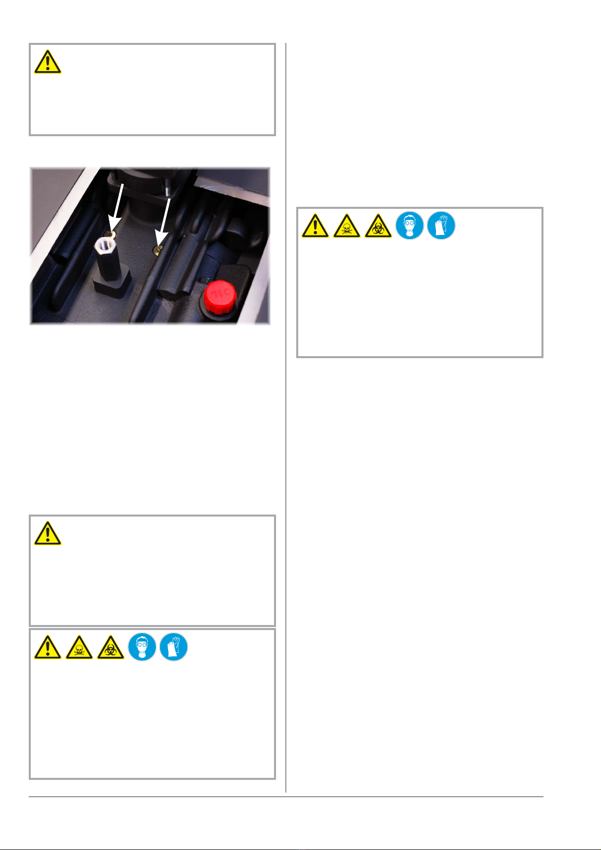
◆Make sure that the anti-pulsation chamber is equipped with a
condensate drain cock (k) (optional; if the condensate drain
cock is missing contact the Busch service)
●Make sure that the suction line does not contain foreign objects,
e.g. welding scales
Pressure Connection
●Make sure that the pressure line fits to the pressure connection (p)
of the compressor
●Make sure that the pressure connection is connected to a pres-
sure-tight flexible hose or a pipe
●Make sure that the pressure line is designed for 2.0 barg and
250 °C
In case of using a pipe:
◆Make sure that the pipe will cause no stress on the
compressor’s connection, if necessary use an expansion joint
●Make sure that the line size of the pressure line over the entire
length is at least as large as the pressure connection (p) of the
compressor
In case the length of the pressure line exceeds 2 m it is prudent to use
larger line sizes in order to avoid a loss of efficiency and an overload of
the compressor. Seek advice from your Busch representative!
●Make sure that the pressure line either slopes away from the
compressor or provide a liquid separator or a drip leg with a drain
cock, so that no liquids can back up into the compressor
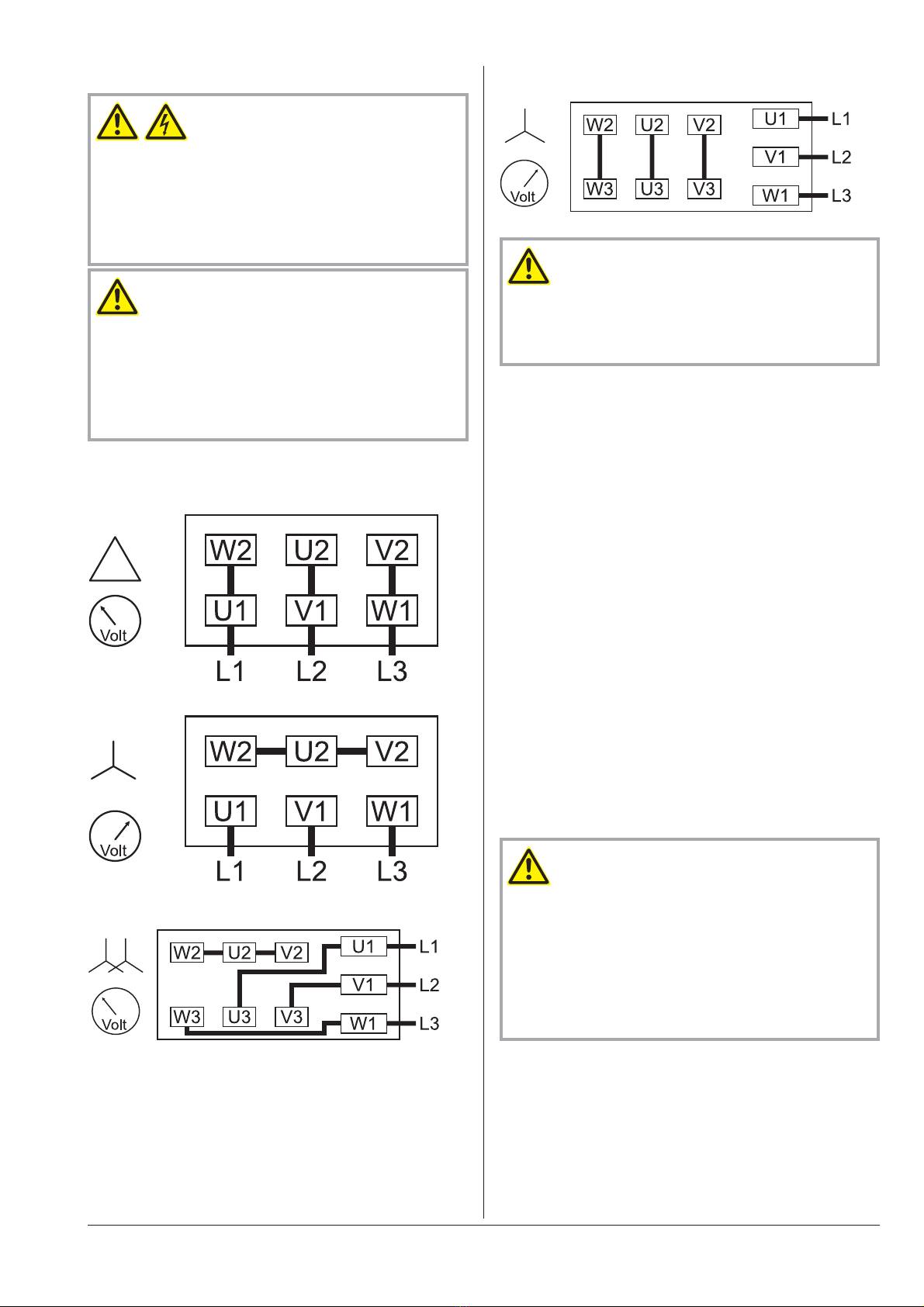
Electrical Connection / Controls
●Make sure that the stipulations acc. to the EMC-Directive
2004/108/EC and Low-Voltage-Directive 2006/95/EC as well as
the EN-standards, electrical and occupational safety directives and
the local or national regulations, respectively, are complied with
(this is the responsibility of the designer of the machinery into
which the compressor is to be incorporated; Úpage 15: note in
the EU Declaration of Conformity).
●Make sure that the power supply for the drive motor is compatible
with the data on the nameplate of the drive motor
●Make sure that an overload protection according to EN 60204-1 is
provided for the drive motor
●Make sure that the drive of the compressor will not be affected by
electric or electromagnetic disturbance from the mains; if necessary
seek advice from the Busch service
In case of mobile installation:
◆Provide the electrical connection with grommets that serve as
strain-relief
Installation
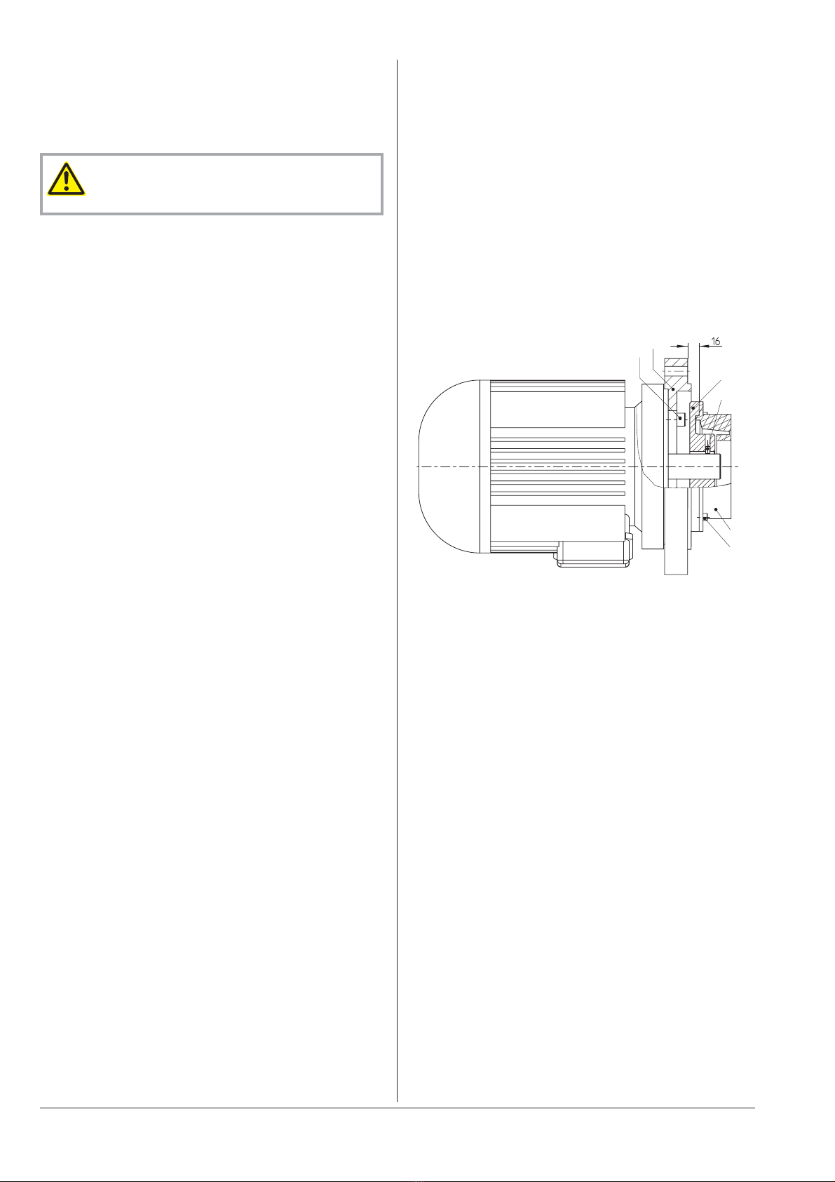
Mounting a NEMA-Motor with
BoWex-Coupling
For certain markets the compressor is available without motor, but with
a NEMA-adaptor flange and a BoWex-coupling.
●Remove the NEMA-adaptor flange (I) from the compressor
●Pull the elastomer part (V) together with the hub (III) off the shaft
of the compressor
●Mount the NEMA-adaptor flange (I) on the motor (the bolts (II)
are not part of the Busch scope of delivery)
●Undo the cylinder screws (VI) and remove the elastomer part (V)
from the hub (III)
●Make sure that the parallel key is inserted into the motor shaft
●Push the hub (III) onto the motor shaft such that the mounting
face of the hub (III) will be located 16±1 mm before the mounting
face of the NEMA-adaptor flange (I) (Úsketch)
●Fasten the hub (III) on the motor shaft using the set screw (IV)
●Apply thread locking agent on the threads of the cylinder
screws (VI)
●Mount the elastomer part (V) on the hub (III) with the cylinder
screws (VI) and tighten the cylinder screws with 14 Nm
●Mount the motor on the compressor
Mounting
●Make sure that the installation prerequisites (Úpage 5) are com-
plied with
●Set down or mount the compressor at its location
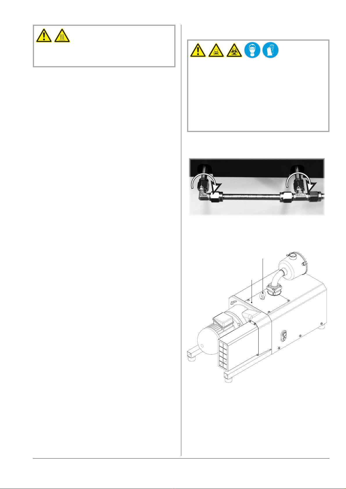
Checking Synchronising Gear Oil
The compressor is delivered with oil filled synchronising gear.
The level shall be slightly above the middle of the sight glass (e).
●Check on the sight glass (e) that the proper amount of oil is filled
Installation and Commissioning MM 1202, 1252, 1322 AP gas tight
page 6 0870144686 / 201205
I
II
III
IV
V
VI