Bicom Systems OfficeBox Gen. 3 User manual

OfficeBox Gen. 3
HARDWARE MANUAL

c
2018 Bicom Systems Ltd.
PUBLISHED BY BICOM SYSTEMS LAB
BICOMSYSTEMS.COM
DOCUMENTATION IS PROVIDED “AS IS” AND ALL EXPRESS OR IMPLIED CON-
DITIONS, REPRESENTATIONS AND WARRANTIES, INCLUDING ANY IMPLIED
WARRANTY OF MERCHANTABILITY, FITNESS FOR A PARTICULAR PURPOSE OR
NONINFRINGEMENT, ARE DISCLAIMED, EXCEPT TO THE EXTENT THAT SUCH
DISCLAIMERS ARE HELD TO BE LEGALLY INVALID.

NOTICE
While reasonable efforts have been made to ensure that the information in this document is
complete and accurate at the time of publishing, Bicom Systems assumes no liability for any
errors. Bicom Systems reserves the right to make changes and corrections to the information
in this document without the obligation to notify any person or organization of such changes.
COPYRIGHT
All rights reserved. No parts of this document may be reproduced, stored in retrieval systems,
or transmitted in any form or by any means, without prior written permission of the publisher.
WARRANTY
Bicom Systems provides a limited warranty on Bicom Systems hardware and/or software.
Refer to your sales agreement to establish the terms of the warranty. In addition, Bicom Sys-
tems’s standard warranty language, as well as information regarding support for this product
while under warranty is available to Bicom Systems customers and other parties through the
Bicom Systems Support website: HTTP://WWW.BICOMSYSTEMS.COM/SUPPORT. Please
note that if you acquired the product from an authorized Bicom Systems reseller, the warranty
is provided to you by said Bicom Systems reseller and not by Bicom Systems.
TRADEMARKS
The trademarks, and logos displayed in this document, are the registered or unregistered
trademarks of Bicom Systems, its affiliates, or other third parties. Users are not permitted to
use such trademarks without prior written consent from Bicom Systems or such third party
which may own the trademark.
Bicom Systems is a registered trademark of Bicom Systems Ltd.
All non-Bicom Systems trademarks are the property of their respective owners.
OBTAINING DOCUMENTATION
For the most up to date version of the documentation, please visit the Bicom Systems Support
website: HTTP://WWW.BICOMSYSTEMS.COM/SUPPORT.


Contents
1Document overview ......................................... 7
1.1 Intended audience 7
1.2 Conventions used in this document 7
1.3 Important safeguards 8
1.3.1 Safetyprecautions ................................................ 8
1.3.2 Power source and power supply . . . . . . . . . . . . . . . . . . . . . . . . . . . . . . . . . . . . 8
1.3.3 Electricalshock ................................................... 8
1.3.4 Equipmentmodifications........................................... 8
1.3.5 Ventilation ....................................................... 8
1.3.6 Placement ....................................................... 9
1.3.7 Regulationsandinformation ........................................ 9
IDevice
2Device overview ............................................ 13
2.1 Hardware specification 13
2.2 Front view of the device 14
2.3 Back view of the device 14
2.4 Supported phones 15
3Hardware assembly ........................................ 17
3.1 Case disassembly 17
3.2 Preparing the motherboard 18

3.3 Securing the motherboard 19
3.4 Preparing X1 sockets 20
3.5 Parts assembly 21
3.6 Inserting cards 22
3.7 Attaching other case plates 22
4Installation ................................................... 23
4.1 Installing the software image 23
4.1.1 WritingimagetoUSBmemory ..................................... 23
4.1.2 Installing the software to the device . . . . . . . . . . . . . . . . . . . . . . . . . . . . . . . . 24
4.2 Mounting 24
4.2.1 Rackmount ..................................................... 24
4.2.2 Wallmount...................................................... 26
4.2.3 Deskplacement ................................................. 28
4.3 Network setup 28

1. Document overview
Administration manual covers the initial process of obtaining the licenses up to the process
of deployment of the OfficeBox appliance. This is explained in simple steps which take a
short amount of time and if followed correctly, will provide a rock solid platform that will
satisfy customers business needs.
1.1 Intended audience
This document is intended for the re-sellers that will be obtaining licenses, and administrators
which will assemble the hardware and install the software for the appliance.
1.2 Conventions used in this document
The document will follow a set of conventions which will give it a different emphasis,
depending on the importance that shown information has. Please observe the following.
W
This is a warning section which emphasizes information of critical importance. It is
crucial to read and adopt the information marked within this section.
N
This section notifies the user about the additional information provided within the
section, that complements the rest of the information in the chapter.
Computer code or similar text is shown like this .
When an emphasis is given to one or more words within normal text, it is emphasized with
bold
,italic, or SPECIAL EMPHASIS, which really depends on the context and the place within
the text.

8Chapter 1. Document overview
1.3 Important safeguards
Although the device is based on low-powered embedded components, for your safety and
proper operation of the device, please read this manual carefully. Malfunctions resulting
from non-compliance with the information provided in this manual are not covered by the
provided guarantee.
1.3.1 Safety precautions
For your protection when setting up your appliance, please observe:
•All cautions and instructions marked on the equipment should be followed,
•
Make sure that your power source voltage and frequency matches the one required by
the appliance’s power supply,
•
Never insert objects through openings in the appliance, as this can be dangerous and
damage your equipment.
1.3.2 Power source and power supply
Please ensure that your power source voltage and frequency matches the one required by
your power supply adapter.
W
Power supply is designed to work with the single-phase power systems. To reduce the
risk of electrical shock, do not plug the equipment into any other power system. If you
are not sure what kind of power system your facility has, please contact the facility
manager or qualified electrician.
W
Not all power adapters will fit your OfficeBox power supply, so usage of power adapters
other than the one supplied with your box is not recommended.
1.3.3 Electrical shock
To reduce the risk of electrical shock, do not disassemble or tamper in any way with the
power supply. Opening the power supply may expose you to dangerous voltage, and incorrect
reassembly will damage your equipment.
1.3.4 Equipment modifications
Equipment hardware tampering or modifications are strictly prohibited by your guarantee.
The hardware configuration will be preset by the official reseller and any change to the
hardware configuration must be done by said reseller. Please do not open your device since
that will void your guarantee.
1.3.5 Ventilation
Although the appliance does not use active cooling, integrated heat pad that transfers heat
from APU to the bottom panel of the appliance, is sufficient as a cooling setup. Nevertheless,
good ventilation space is suggested for additional protection. Openings on the appliance
must not be covered or blocked and should be kept free from the dust.

1.3 Important safeguards 9
1.3.6 Placement
Openings on the top cover and side panels are meant as a ventilation for any amount of
excess heat that is not transferred to the bottom panel, and they should be kept free from
obstructions. Make sure that appliance is stored in a well vented place and no objects are
placed on top of it, as well as avoiding placing the device on top of other radiating surfaces.
W
Do not put the appliance near a radiator or any other heat emitting device. Failing to do
so can cause your appliance to overheat and malfunction.
1.3.7 Regulations and information
This device complies with the CE and FCC Rules and Regulations which can be obtained
from the supplier.


I
2Device overview ................. 13
2.1 Hardware specification
2.2 Front view of the device
2.3 Back view of the device
2.4 Supported phones
3Hardware assembly ............. 17
3.1 Case disassembly
3.2 Preparing the motherboard
3.3 Securing the motherboard
3.4 Preparing X1 sockets
3.5 Parts assembly
3.6 Inserting cards
3.7 Attaching other case plates
4Installation ........................ 23
4.1 Installing the software image
4.2 Mounting
4.3 Network setup
Device


2. Device overview
OfficeBox is a telephony device designed and manufactured by Bicom Systems Ltd. and
powered by our own PBX software.
Depending on the expected functionality, the device comes in two editions:
•Business edition - with our PBXware telephony software,
•Key systems edition - with our Key systems telephony software
Hardware wise, the appliance supports OpenVox and Sangoma analog and T1 cards giving a
variety of options to chose from.
2.1 Hardware specification
OfficeBox is a highly embedded appliance owning its integrated nature to latest technology
advancements, which in turn guarantees small dimensions, minimal number of parts, and
no moving parts whatsoever. This also guarantees low temperature footprint, as previously
noted, and minimal power consumption.
This is achieved by utilizing apu2c2 x86 embedded motherboard from PCEngines. As
such, motherboard specification are:
•6x6" format
•AMD Embedded G series GX-412TC, 1 GHz quad Jaguar 64 bit core,
•2GB DRAM,
•three Gigabit Ethernet channels (Intel i211AT),
•two external USB 3.0 and two internal USB 2.0 ports,
•three front panel LEDs,
•one front panel pushbutton,
•12V DC, 2.5 mm jack,
•COM2 (3.3V RXD / TXD)

14 Chapter 2. Device overview
2.2 Front view of the device
Figure 2.1: officeBox Front mask.
As can be seen on figure 2.1, OfficeBox has only one through-hole control button and
three LEDs used for signalling the system status.
•PWR - Left most LED, signals that the system is powered on,
•SYS - Middle LED, signals that the system is started and operational,
•
CALLS - Right most LED, signals that the system has active calls running at the
moment.
Reset through-hole button has several purposes, but for the end user two most important ones
are:
•Press the button and hold it for three seconds, release it and the appliance will reboot,
•
Press the button and hold it for six seconds, release it and the appliance will shutdown.
W
Holding the Reset button for more than 6 seconds will trigger the factory reset, and as a
consequence all contained data will be lost.
2.3 Back view of the device
Figure 2.2: OfficeBox Back plate.
Rear panel of the appliance is custom made so it can accommodate one or two cards (see
Hardware Specification document). Two blanking plates, as seen on figure 2.2, are used to
cover the holes where cards might be used. Depending on the configuration, there will be at
least one analog card, or two in better equipped devices.

2.4 Supported phones 15
The back plate will also have named cutouts for all the connectors that the motherboard
provides. From left to right, the connectors are:
•
CONSOLE - COM port used as a serial connection to the appliance, just in case a
certified technician needs to debug it (for simplicity reasons, appliance does not have
any monitor connectors such as VGA, DVI or HDMI),
•
LAN - Standard ethernet port which is used as the main communication port for the
appliance.
•
MAN - Managed Area Network, ethernet port used for the manual connection to the
appliance which is needed to discover or setup the network details for the LAN port
(See Section 4.3).
•
RAN - Replication Area Network, dedicated ethernet port used for network replication
to a second appliance for backup purposes.
•USB - two USB 3.0 ports for various needs.
•POWER JACK - 12VDC power connector.
2.4 Supported phones
Depending on the edition of the appliance, number of supported phones will vary. If the
appliance is a business edition appliance, it will support all the models that are officialy
supported by PBXware. Please check out our wiki1page for a complete list.
1http://wiki.bicomsystems.com/UADs

3. Hardware assembly
Before anything could be done with the device, it must be assembled into its designated
aluminium case. Tools needed for this are the Phillips screwdriver and Allen key which
comes packaged with the appliance. These should be enough to work with all the screws in
the appliance.
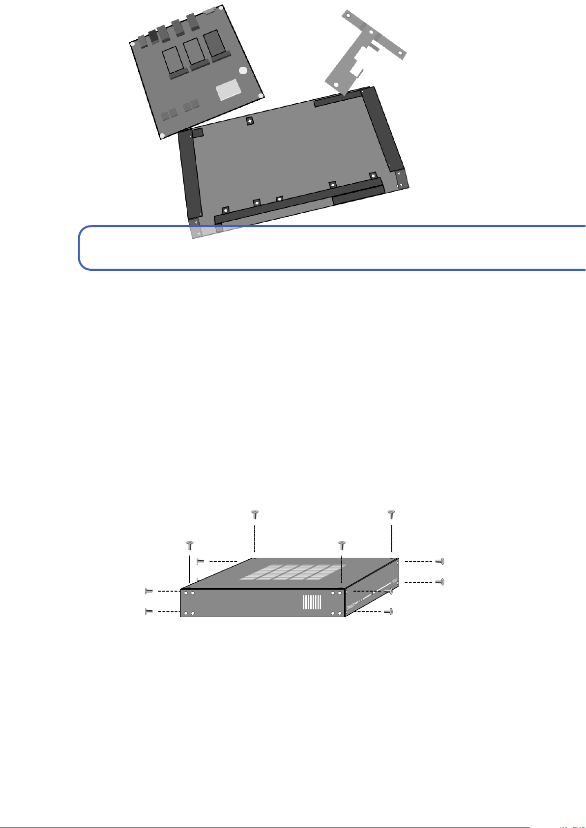
3.1 Case disassembly
Case disassembly is a pretty straightforward matter and can be described in several steps.
Figure 3.1: Case disassembly.
STEP 1.
Remove the top cover first by unscrewing the four Allen head screws from the top
cover, and gently lift it up.
18 Chapter 3. Hardware assembly
N
There are two types of screws with differing threads used in the assembly process.
Please remember where they all go.
If you switch screws and use them with wrong threads, it could lead to the destruction
of the threads in the holes or on the screws.
STEP 2.
Remove the front and back plate next. They both have four screws attaching them
to the main body of the case.
STEP 3.
Remove the T-shaped card holder, if present in the case. It is secured by only two
screws.
STEP 4. Remove the four screws from the bottom plate so you could detach side panels.
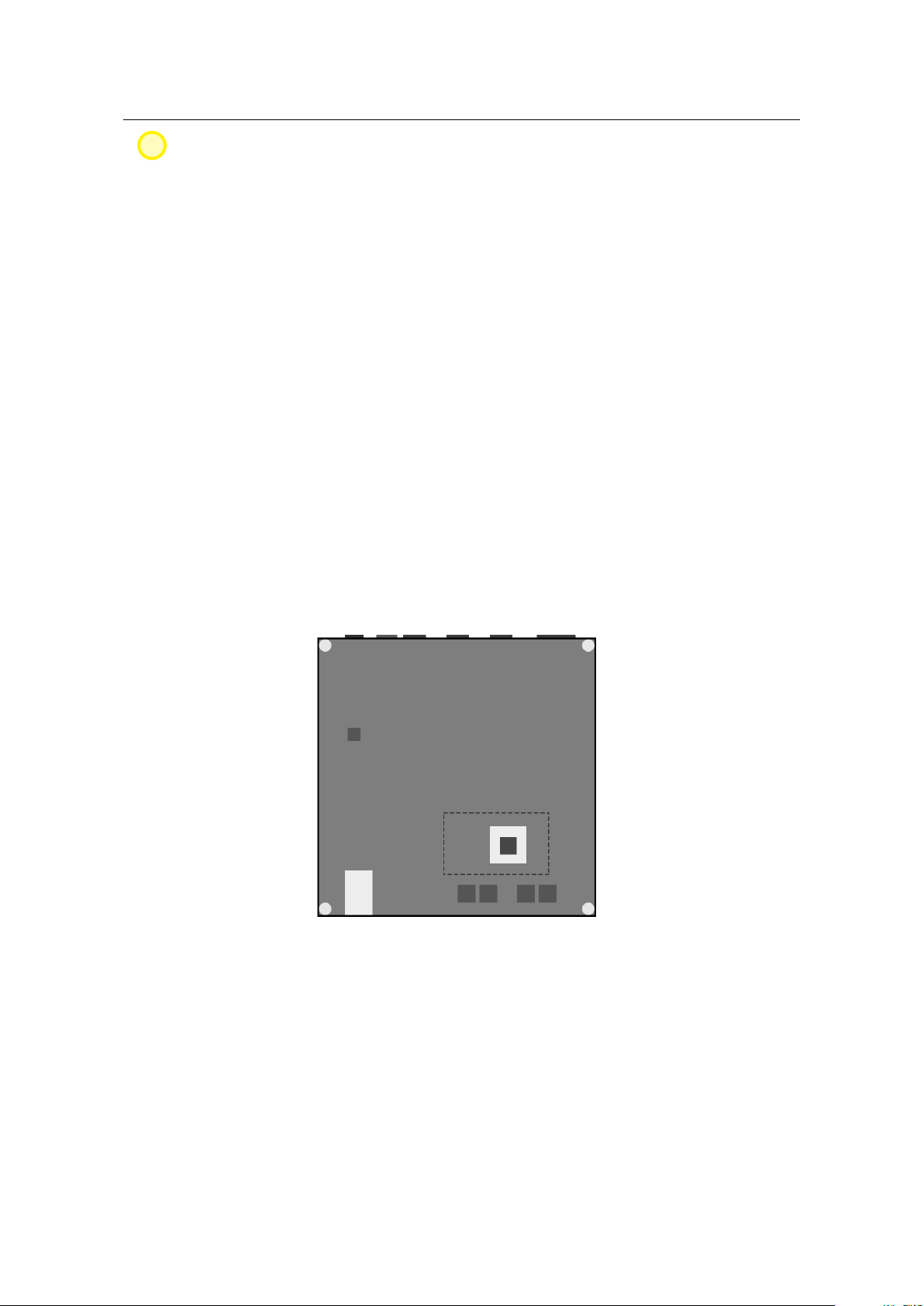
3.2 Preparing the motherboard
STEP 1.
Unpack both the motherboard and the APU heat sink from the plastic wrapping.
Use the small double sided sticky tape that came in the heat sink package and center it on the
APU on the motherboard.
As you can see on figure 3.2 the dashed line shows the position where heat sink should
be placed over the APU with sticky tape on it.
Figure 3.2: Placement for the heat sink.
The APU heat sink should have one side completely covered with double sided sticky
tape and the other should be clean. Place the clean side of the heat sink against the APU.
STEP 2.
To connect the analog cards to the motherboard later on, you will use the mini PCI
express card to PCI express X1 socket adapter which is basically a mini PCI card connected
with included flat cable to the PCIx1 socket.
Place the motherboard as seen on figure 3.3.

3.3 Securing the motherboard 19
Figure 3.3: Motherboard assembly.
If attaching two analog cards, first insert the mini PCI card into the left mini PCI slot, by
placing the card diagonally in the slot and gently pressing downwards until you hear a click.
Place the second mini PCI card the same way as the first one, into the middle/2nd mini
PCI slot.
Lastly, insert the 16GB mSATA SSD storage into the rightmost slot marked mSATA the
same way as the mini PCI cards.
3.3 Securing the motherboard
Figure 3.4: Motherboard placement.
STEP 1. Remove the protective plastic wrapper from the heat sink under the motherboard.

20 Chapter 3. Hardware assembly
While we did ensure that the case is simple as possible for handling, the part where
you insert the motherboard into the case can be a bit tricky. Take the motherboard, turn its
connectors to the back of the case, tilt it towards the front end of the case so you could slide
it slightly under the front slotted aluminium sheet which protrudes from the bottom plate.
STEP 2.
Gently slide it under the slot, just enough so its back end can pass under the
aluminium lip, which is used for T-frame attachment.
W
While sliding the motherboard in the case, be very careful with the heat sink under the
motherboard and do not let it stick to the bottom plate until you have positioned the
motherboard so that you can secure it with four screws in the corners.
STEP 3.
When the corner screw holes on the motherboard align with the bottom plate
threads, fasten the motherboard with four screws that came with it.
3.4 Preparing X1 sockets
X1 sockets come in two varieties:
•GH-EMLX1 - attached to the T-frame,
•GH-EMRX1 - attached to the inner side of the right side panel.
The nomenclature references Left and Right orientation, when looking from the back of the
device.
Figure 3.5: Attaching X1 socket.
As you can see on figure 3.5, the GH-EMLX1 is positioned in such a way that white
power connector comes on top while the PCIx1 socket is bottom oriented. The GH-EMRX1
is positioned rotated by 180 degrees, so that white power connector points to the bottom
while card connector is on top.
Table of contents


