Karel MS48 User manual

Telephone System
Central Téléphonique
Centralita
Mini Guide... Mini Guía

Introduction
In this guide you will find overall information about Karel MS48 Telephone System in 4 main chapters;
1) System Overview (pg 2): General technical information about KAREL MS48 Telephone System is
presented.
2) Installation (pg 3): Installation of the system and its accessories is presented.
3) Basic Programming (pg 8): Basic programming steps to make the system run with basic functions are
presented.
4) User Features (pg 10): Most commonly used user facilities are presented.
This guide is meant for quick reference only, please contact your dealer for detailed information.
1

System Overview
Karel MS48 Telephone System in the basic capacity serves for 4 lines and 12 extensions, and with its modular
structure, the capacity can be expanded up to 48 ports by adding expansion boards.
This system with its flexible hardware and rich software structure is designed to meet your requirements. The
wide range of accessories is to enhance the functionality of the system whilst keeping the low cost levels.
The extension numbering starts at 11 and is a two digit number for the systems with capacities 4/12 and 6/18,
whereas it starts at 111 and is a three digit number for bigger capacities. The line numbering starts at 01 and is
a two digit number for all capacities.
The system parts and accessories :
1) EXP48 (4/12) : Expansion Module for 4 lines and 12 extensions.
2) EXP48 (2/6) : Expansion Module for 2 lines and 6 extensions.
3) EXP48 (0/16) : Expansion Module for 16 extensions.
4) SPS48 : Power Card of the system.
5) LT48(-H) : Feature Phone, with a multi lingual, menu driven 2-line x 16-character LCD, 10
programmable double function memory keys with dedicated LEDs and 6 special
function keys. Handsfree is optional.
6) OP48(-H) : System Console, with a Busy Display Panel to monitor the states of all lines and
extensions,8-characterdisplaytoshowthetime,thenumberdialedandsomesystem
features, and 6 special function keys. Handsfree is optional.
7) DSS80 : Direct Station Select Module, with 80 programmable double function memory keys
with dedicated LEDs.
8) DSS40 : Direct Station Select Module, with 40 programmable double function memory keys
with dedicated LEDs, a Busy Display Panel and a 2-character display to monitor the
states of all ports.
9) EVM48 : Integrated Auto Attendant & Voice Mail Module to serve as a robot operator and let
the users leave voice messages to private mailboxes.
10) CM48-W : Call Record Listing Interface to establish the connection to a PC to serve as a
statistics and database program for the call records.
11) PK48-D : PC-Console Interface to serve as a PC-Console and a maintenance module.
12) RS232 : RS232 Interface for connection to a serial printer to have the call records printed, an
alternative to CM48-W.
13) KY16 : Special Karel Mini Printer (16-column) to have the call records printed, an alternative
to RS232 and CM48-W.
14) PG100 : Local Pager to page the extensions equipped with beepers (receivers) so that they
can pick up their calls or attend later.
15) DY26 : Doorphone.
16) FPBASE & FPEXP : Filter & Protection Units for four lines or remote extensions.
2
I

Installation
It is recommended to install the MS48 system and accessories (if any) in the following order:
+Hanging the system on the wall
+Installing DY26 Doorphone
+Installing CM48-W Call Record Listing and/or PK48-D PC-Console or RS232 Serial Printer Interfaces
+Installing EVM48 Auto Attendant & Voice Mail Module
+Installing EXP48 Expansion Cards & MFR48 MF Receiver Card
+Installing KY16 Mini Printer
+Wiring the extensions and lines
+Installing PG100 Local Pager
+Installing FPBASE & FPEXP Filter & Protection Units
Figure 1 - Locations of connectors on the motherboard
Connectors:
1 - 4 Lines 01 to 04
5 - 16 Extensions 11 to 22
(or 111 to 122)
17 External Relay
18 External Music Source
X1 Serial Data
X2 KY16 Mini Printer
X3 DY26 Doorphone
X4 Reserved for future use
A1 - A3 CM/PK or RS232 Card
B1 - B3 EVM48 Card
C1, C2 MFR48 Card
D1 - D5 EXP48 (2/6) Card
D1 - D7 EXP48 (4/12)/EXP48
(0/16) Card
3
B2
D4
D5
S3
D3
D1
B3
A3
C1 B1 X3 A1
A2
C2
SPS48
X1 X2
G1
MOTHERBOARD
D6
S1
D7
Cabinet
16 15 14 13 12 11 10 9 8 7 6 5 4 3 2 1
17
18
Mains cable
Mains fuse
On/Off switch
Cable hole
D2
X4 S4
S2
II

II.1HANGING THE SYSTEM ON THE WALL
1) Place the template on the wall to select the proper location for the system.
2) Drill two holes as shown on the template, place the screws and hang the system through the pear holes
at the back of the cabinet.
II.2INSTALLING DY26
1) Hang the doorphone on the wall.
2) Pass the free end of the cable through the cable hole at the bottom part of the system cabinet.
3) Insert the 4-pin plug into the Doorphone socket (X3) on the motherboard (see Figure 1).
II.3INSTALLING CM48-W AND/OR PK48-D OR RS232
To install the hardware:
1) Insert the pin connectors of the card into the A1-A3 connectors on the motherboard (see Figure 1).
2) Pass the pin connector end of the cable through the cable hole at the bottom part of the cabinet.
3) Insert the pin connector into the socket on the PKCR or RS232 card.
4) For the PKCR card, connect the 25-pin D-type plug to the security plug and the security plug to the PC.
For the RS232 card, connect the 25-pin D-type plug to your serial printer.
To set up the CM48-W /PK48-D software on the PC:
1) Insert the diskette into the PC.
2) Run INSTALL.EXE file in the diskette and follow up the prompted commands.
NOTE: Using a single PKCR card, a cable and a security plug, you can set up both the CM48-W and PK48-D
programs on the PC.
II.4INSTALLING EVM48
1) Remove the screw S4 on the motherboard and fix the brass card holder instead (see Figure 1).
2) Insert the pin connectors of the card into the B1-B3 connectors on the motherboard (see Figure 1). Then fix the
screw to the brass card holder to fix the card.
To install optional EVM-FE (Auto Attendant Expansion Module) or EVM-DE (Voice Mail Expansion Module):
1) Insert the pin connectors on the EVM-FE / EVM-DE card to the male ones on the EVM48 card (see Figure 2).
Figure 2 - Installation of EVM-FE and EVM-DE
4
F1 F2 D3 D2 D1
EVM48
Optional
EVM-FE Optional
EVM-DE

II.5INSTALLING EXP48
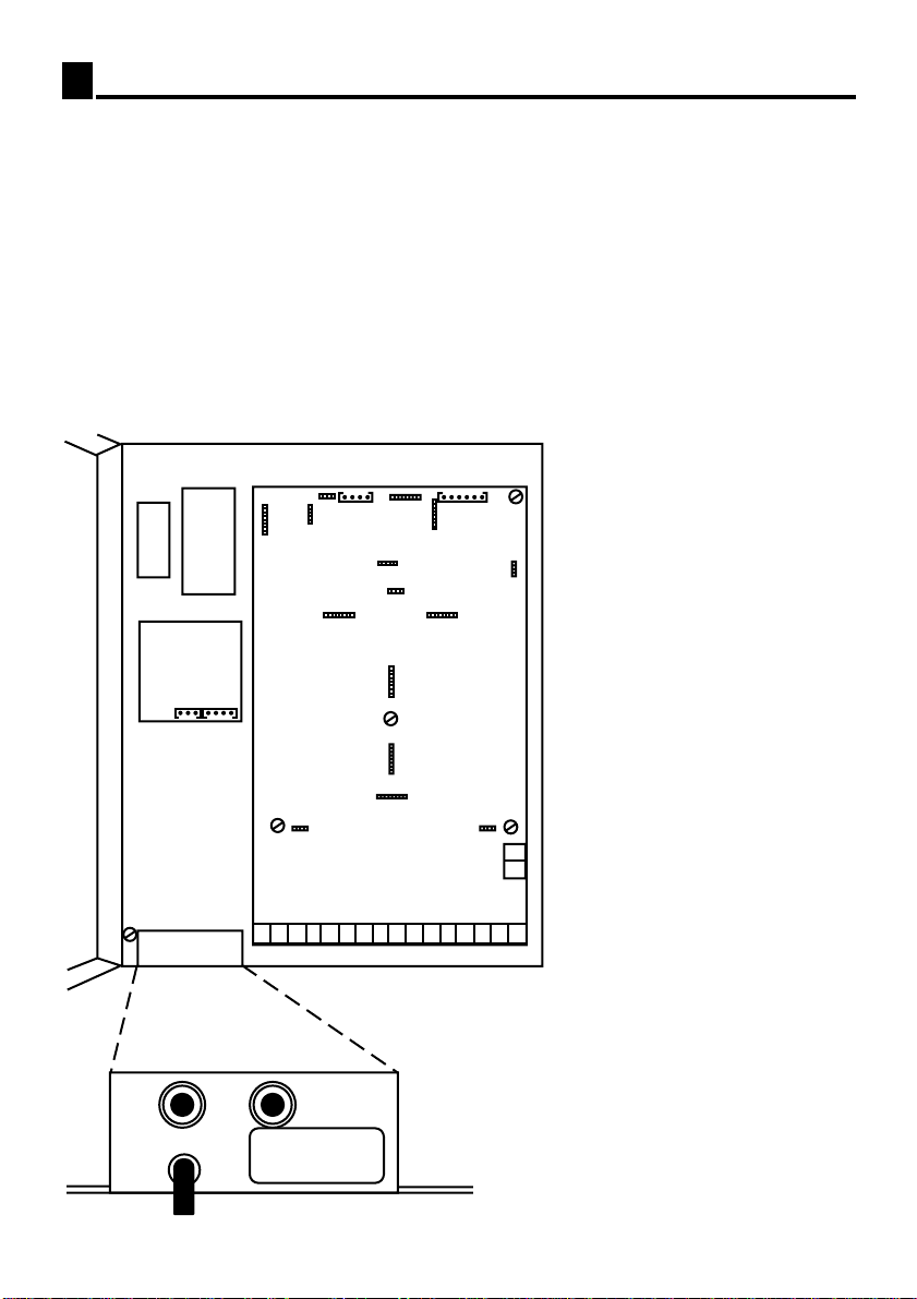
1) Remove the screws S1-S3 from the motherboard and fix the brass card holders instead (see Figure 1).
2) Insert the pin connectors of the EXP48 (2/6) card to the D1-D5 connectors or the pin connectors of the
EXP48 (4/12) / EXP48 (0/16) card to the D1-D7 connectors on the motherboard (see Figure 1). Then fix
the screws to the brass card holders to fix the card.
3) If a second expansion board is to be inserted on the first one, then instead of fixing the screws as explained
in item "2", fix the brass card holders and insert the pin connectors of the second expansion card to D1-D7
connectors on the first expansion board. Then fix the screws to fix the card.
4) If an EXP48 (0/16) or EXP48 (4/12) card is installed on the motherboard, then the MFR48 card must be
installed as well by inserting the pin connectors on the MFR48 card to the C1&C2 connectors on the
motherboard (see Figure 1).
NOTE: At most two expansion cards can be installed on an MS48, but, both cannot be EXP48 (2/6) or
EXP48 (0/16).
NOTE: Screw "S2" is very important as chassis ground of the system is carried to the expansion boards via
the brass card holder fixed here. Electrical safety of the system depends on this screw.
NOTE: If there are two EXP48 cards and if one of them is EXP48 (2/6), EXP48 (2/6) must be installed on top.
II.6INSTALLING KY16
1) Adjust the dipswitches on the KY16 card; 1 and 2 to OFF, 3 and 4 to ON.
2) Hang KY16 on the wall.
3) Pass the 4-pin free end of the KY16 data cable through the cable hole at the bottom of the cabinet and plug
it to X2 on the SPS48 card (see Figure 1).
4) Plug in the mains cable of KY16.
II.7WIRING OF THE EXTENSIONS AND LINES
1) Pass the cables of the extension telephones and lines through the cable hole (see Figure 1).
2) Insert the two wire (A-B wires) of the telephone cable or line cable to the relevant connector (Connectors
1 to 16 in Figure 1).
To make the data wiring of LT48(-H), OP48(-H), DSS80 and/or DSS40 :
3) Pass the 3-pin free end of the System Data Cable through the cable hole and plug it to X1 connector on
SPS48 card (see Figure 1 and 3).
4) Connect Data, +12 VDC, GND signals from the relevant pins of the connection box of system data cable to
the relevant pins of the connection box of the telephone data cable of LT48(-H), OP48(-H), DSS80 or DSS40
in parallel. In other words: All "+" terminals must be connected among themselves, all "-" terminals must be
connected among themselves and all "D" terminals must be connected among themselves.
5) For LT48(-H) and OP48(-H) connect A-B wires from the relevant extension connector to the A-B pins in the
connection box of the telephone data cable.
6) Connect one of RJ11 plug ends of the telephone data cable to the connection box and the other end to the
LT48(-H), OP48(-H), DSS80 or DSS40 (see Figure 3).
5

To set the extension numbers:
a) OP48(-H): Keep the "Message" key pressed till the extension number starts blinking on the display and "A"
appears next to it. Then, press the same key repeatedly till the correct extension number appears on the
display.
b) LT48(-H): Keep the "H/R" key pressed till the extension number starts blinking on the display. Then, press
the same key repeatedly till the correct extension number appears on the display.
c) DSS80: Press the "A" key till the 3rd beep. Then enter the extension number.
d) DSS40: Press the "Pa/Pr" key till the 2nd beep. Then, press the same key repeatedly till the correct
extension number appears on the display.
NOTE: LT48(-H), OP48(-H), DSS80 and DSS40 can only be connected to the first 16 extensions of the
system.
NOTE: A total of 10 LT48(-H), OP48(-H), DSS80 or DSS40 units may be connected to the system.
II.8INSTALLING PG100
1) Hang the PG100 on the wall.
2) Connect the Data, +12 VDC and GND signals of System Data Cable in parallel to the connection box of the
PG100 Data Cable and plug the RJ plug to the Data connector at the bottom face of the local pager (see
Figure 3).
Figure 3 - Wiring Karel Special Telephone, DSS and PG100 on MS48
System Data Cable
1) Data
2) GND
3) A (tip)
4) B (ring)
6) +12VDC
2
6
1
RJ11
SPS48
Card
MOTHERBOARD
A-B Lines
RJ11 RJ11 RJ11 RJ11 RJ11 RJ11 RJ11
A-B Lines A-B Lines
Data cable parallel
to all sets below
LT48(-H) DSS80 DSS40 DSS40 OP48(-H)LT48(-H) PG100
2
6
1
4
3
2
6
1
2
6
1
4
3
2
6
1
2
6
1
2
6
1
2
6
1
4
3
X1
6

II.9INSTALLING FPBASE AND FPEXP:
To install the FPEXP modules on an FPBASE or on another FPEXP:
1) Remove the screws at the corners of base card.
2) Passtheboltendsofthebrasscardholdersthroughtheholesatthecorners of the FPEXP card. Thenplace
the plastic spacers to three of these bolt ends. For the fourth brass card holder which is lying on the
grounding pin of the FPBASE unit, fix the two nuts to the bolt end as a grounding spacer.
3) Fix the bolt ends to the holes of the bottom module.
4) Place the FPEXP cover on the card and fix the screw to the brass card holder at four corners (see Figure 4).
To make the proper wiring:
1) Connect the two wires of the PTT line or far extension to the PTT connector of FPBASE or FPEXP modules
(see Figure 5).
2) Connect the two wires from the PABX connector of FPBASE or FPEXP to the relevant line or extension
connector of the system (see Figure 1 and Figure 5).
3) Connect the GND pin on the FPBASE unit to the chassis ground of the system at G1 (see Figure 1).
Figure 4 - Installation of FPEXP on an FPBASE
Figure 5 - Wiring of FPBASE & FPEXP
7
PABX PABX PABX PABX
PABX PABX PABX PABX
PTT PTT PTT PTT
PTT PTT PTT PTT
To the system
FPEXP
From line or far extension
To the system Pear holes
From line or far extension
GND
GND
FPEXP
FPBASE
Chassis ground
of the system

Basic Programming
After the system is powered on, it will take a couple of minutes for the system to initialize itself and recognize
all the peripherals automatically. Then it is necessary to do some basic programming to make the system run
properly. To do this, the system must be put in the programming mode by dialing 877777 from the system
supervisor's telephone. After all the necessary programs are entered, the programming mode must be exited by
dialing 877778 again from the system supervisor's telephone.
System supervisor is the operator of the system by default (extension 11 or 111).
First "Loading the country specific parameters" program must be entered (section III.3).
The codes in sections III.1, III.2, III.12 were given as the basic settings for the system even though they are not
program codes, but operator only facilities.
III.1 SETTING THE TIME
1) 88 + Hour (00..23) + Miinute (00..59)
III.2 SETTING THE DATE
1) 833 + Day (01..31) + Month (01..12) + Year (00..99)
III.3 LOADING THE COUNTRY SPECIFIC PARAMETERS
1) 8009 + Country Parameter (0..8)
)1 : Greece 2 : Poland & Pakistan 3 : Portugal
4 : Spain 5 : Russia & CIS Countries 6 : Romania
7 : Malta 8 : Republic of South Africa 0 : Others
2) 8259
III.4 PUTTING THE LINES IN SERVICE
1) 89 01 9 0
2) 89 + Line Number + 1 + Signaling (0 / 1)
)1 : DTMF signaling
0 : DP signaling
III.5 DEFINING EXTENSIONS’ CALL AUTHORITY LEVELS
1) 887 11 9 0
2) 887 + Extension Number + Call Authority Level (0 / 1 / 2 / 3 / 4 / 5)
)0 : Only internal calls
1 : Internal & local calls
2 : Internal & local & long distance calls
3 : All calls
4 : Only the numbers in common pool & internal calls
5 : Only the numbers in common pool & internal & local calls
III.6 DEFINING THE LOCAL PREFIX
1) 80074 + Local Prefix (at most three digits)
)To cancel : 8008
8
III

III.7 SHARING LINES AMONG THE EXTENSIONS
To define the extension groups:
1) 801 + Extension Number + Group (00..15)
)Extensions in group 15 can access any idle line.
To dedicate the lines to the extension groups:
1) 802 + Line Number + Extension Group Numbers
)You can enter as many extension group numbers up to 15 as you like. If 15 is entered as
extension group then that line cannot be accessed by any extension.
)Hang up to end the program.
III.8 DEFINING RINGING / NIGHT RINGING EXTENSIONS
1) 800 + Line Number + Ringing Extension Number + 0 + 0 + 0 +0
(NOTE: The fourth 0 can be entered only if Voice Mail is installed.)
2) 879
3) 800 + The Same Line Number + Night Ringing Extension Number
4) 878
III.9 DEFINING PARALLEL OPERATORS
1) 8085 + Extension Number To Ring In Parallel With The Operator.
)At most four extensions may be defined as parallel operators.
)To cancel : 8086
III.10 RECORDING AUTO ATTENDANT MESSAGES
1) 864 + Message Number (00..23) + Message
)00 : Greeting message 01 : Missing Digit message
02 : Busy Extension message 03 : No Answer message
04 : Invalid Number message 05 : Wait message
06 : Inaccessible Extension message 07 : Transfer message
08 : Night Mode Greeting message 09 : DISA Greeting message
10 : Password message 11..23 : General purpose messages
)To delete all Auto Attendant messages : 86444
III.11 DEFINING AUTO ATTENDANT/DISA LINES
1) 8070 + Line Number + Line Type (8 / 9 / 0)
)8 : Auto Attendant line 9 : DISA line 0 : Normal line
III.12 ACTIVATING AUTO ATTENDANT LINES
1) 8741
)Dial 8741 after defining all Auto Attendant lines and recording all messages.
)To deactivate : 8740
III.13 DEFINING CALL RECORD LISTING DEVICE
1) 877 + 5 + Device Parameter (0 / 1 / 2)
)0 : PC or serial printer
1 : Condensed mode serial printer
2 : KY16 Mini Printer
Karel MS48 Telephone System has lots of more programs to meet your specific requirements. Please contact
9

User Features
In this section, feature activations for users with standard telephones are presented. LT48(-H) Feature Phone
users do not need to follow these steps as they can easily process their calls by following the menu driven
prompts of their telephones. DSS80 or DSS40 users may also activate most of the given facilities by a single
key stroke.
Ext. Nr. )Extension Number
PTT Nr. )External Number
Line Nr. )Line Number
Mes. )Message
#)Hook flash; either with "#" key (on DTMF telephones) or,
with "Flash" key or,
with "R" key or,
with "Hook-switch".
∗∗)Hang up; either with "∗∗" key (on DTMF telephones) or,
with "Hook-switch".
MAKING INTERNAL CALLS
To call the operator 0
To call an extension Ext. Nr.
To page an extension 867 + Ext. Nr.
To page an extension group 865 + Ext. Nr (any extension from the group)
To page all extensions 866
To camp on a busy extension or line Wait
To signal the called busy extension 1
To intrude a conversation 0 or 5
To call back a busy or non answering extension 81
To call back a busy line 81
To cancel call back 81
MAKING EXTERNAL CALLS
To make a call through any line 9 + PTT Nr.
To make a call trough a specific line 7 + Line Nr. + PTT Nr.
To make a call and mark it in the call records 790 + PTT Nr.
To make a call and associate it with an account code 797 + Account Code + PTT Nr.
To make a call from any phone to your account 797 + Forced Account Code + PTT Nr.
To make a call from any phone using your password 799 + Your Ext. Nr. + Password + PTT Nr.
To make a call from your locked phone 9 (or 7+Line Nr.) + Password + PTT Nr.
To call a number from the common pool 5 + Common Pool Nr.
To call a number from your private pool 6 + Private Pool Nr.
To redial the last number 60
To Auto-dial from common pool 78 + Common Pool Nr.
To Auto-dial from private pool 77 + Private Pool Nr.
To Auto-dial the last number 770
To cancel Auto-dial 77 + ∗∗
IV
10

ANSWERING CALLS
To answer a call Lift the handset
To pick up an external call 3
To pick up the call of an extension 82 + Ext. Nr.
To pick up the call of an extension in your group 5
FORWARDING CALLS
To forward calls to an extension (from your phone) 85 + Ext. Nr.
To forward calls to an extension (from any phone) 855 + Your Ext. Nr. + Ext. Nr.
To cancel call forwarding (from your phone) 85 + ∗∗
To forward unanswered calls to an extension 86 + Ext. Nr.
To cancel unanswered call forwarding 86 + ∗∗
To disable / re-enable forwarding to your phone 889 / 888
PROCESSING CALLS
To put a call on hold /retrieve a call on hold #
To park a call / retrieve a parked call # + 4 / 4 (# + 3 / 3 for the operator)
To retrieve a call parked by another extension 44 + Parking Ext. Nr.
To retrieve a call parked by the operator 4 + Parked Line Nr.
To transfer a call # + Ext. Nr.
To make three party conference;
with two external parties 9 + PTT Nr. + # + 4 + 9 + PTT Nr. + # + 9
with two extensions Ext. Nr. + # + 5 + Ext. Nr. + #
with one external party and one extension 9 + PTT Nr. + # + 5 + Ext. Nr. + #
To transfer an external call to an external number # + 4 + 9 + PTT Nr. + # + 6
To make a hook-flash to an external line # + 9
To increase the receive level of an external call # + 55
PASSWORD SERVICES
To define a password 836 + Password (000..250)
To change the password 836 + Current password + New password
To delete the password 836 + Password + ∗∗
To lock your phone 837 + Password + 1
To unlock your phone 837 + Password + 0
REMINDER SERVICES
To activate one time reminder 838 + Hour + Minute
To activate one time reminder with message (1) 8389 + Hour + Minute + Mes.
To activate the daily reminder 8387 + Hour + Minute
To activate the daily reminder with message (1) 83879 + Hour + Minute + Mes.
To cancel any reminder 838 + ∗∗
CONFIGURING YOUR PHONE
To set / cancel your phone ring once for each call 831 / 830
To listen to music from your handsfree phone/cancel 857 / 857
To activate / deactivate your beeper(2) 741 / 740
To activate / deactivate the headset operation 742 / 742
To enter numbers in your private pool 84 + Private Pool Nr. + PTT Nr.
(1) Available only if Voice Mail is installed.
(2) Available only if Local Pager is installed. 11

MESSAGE SERVICES (3)
To leave a message to an extension 82 + Mes.
To listen to new messages left for you 8646
To listen to all messages left for you 8645
To save a message while listening 8
To rewind a message while listening 0
To skip a message while listening 1
To clear a message while listening 9
To record your external call # + Your Ext. Nr.
To leave a temporary absent message to your phone 8648 + Mes.
To record an answering machine message 7372
To activate your answering machine message 7371
To deactivate your answering machine message 7370
To clear your answering machine message 7373
HOTEL SERVICES
To activate baby monitor state from the room 858 + Leave the phone off hook
To monitor the room from another phone Your Room Nr. + 9
To set the room state 730 + 0 (clean) / 1 (being cleaned) / 2 (dirty)
To activate meet me call (by the staff) 738 + Staff Nr. (0..9)
To make a meet me call (by the operator) 738 + Staff Nr. (0..9)
DOORPHONE SERVICES
To call the doorphone 110 (10 for capacities of 4/12 or 6/18)
To open the door 151 (29 for capacities 4/12 and 6/18)
To open the door while speaking to doorphone 2
CALL RECORD LISTING SERVICES (4)
To list the call records of an extension or line 8766 + Ext. Nr. or 0+ Line Nr.
To list all the call records / stop listing 8767 / 8768
To list the total cost of calls of an extension 8764 + Ext. Nr.
To clear the call records of an extension or line 8765 + Ext. Nr. or 0 + Line Nr.
To list the numbers in the common pool 746 or 826
To list the parameters of an extension or a line 839 + Ext. Nr. or 0 + Line Nr.
To list the parameters of all extensions and lines 8399
To feed a page on KY16 Mini Printer 8763
To feed a line on KY16 Mini Printer 8762
To pause KY16 Mini Printer 8760
To restart KY16 Mini Printer 8761
(3) Available only if Voice Mail is installed.
(4) Available only for the operator if any Call Record Listing device is installed.
12

OPERATOR ONLY SERVICES
To transfer an external call and receive it back
after the extension hangs up # + 0 + Ext. Nr.
To park / retrieve multiple calls # + 4 / 4
To activate the internal music source 8322
To activate the external music source 8321
To deactivate music 8320
To set time 88 + Hour + Minute
To set date 833 + Day + Month + Year (two digits)
To activate/ deactivate night mode 879 / 878
To enter numbers in the common pool 834 + Common pool no + PTT Nr.
To set alarm time for an extension 8388 + Ext. Nr. + Hour + Minute
To set alarm time with message for an extension(5) 83889 + Ext. Nr. + Hour + Minute + Mes.
To cancel the alarm of an extension 8388 + Ext. Nr. + ∗∗
To enable / disable the parallel operators 8561 / 8560
To forward external calls to an external number 835 + Line Nr. + PTT Nr.
To cancel external call forwarding 835 + Line Nr. + ∗∗
To set the state of the hotel room 730 + Ext. Nr.+ 1 (Vacant) / 2 (Occupied) / 3
(Reserved) / 4 (Out of service)
To query the state of a hotel room 731 + Ext. Nr. + 1 / 2 (print) + 1 / 2 (print)
To set check-in / check-out 732 + Ext. Nr. + 1 (check-in) / 2 (check-out)
(5) Available only if Voice Mail is installed.
Footnote
If your system is malfunctioning in any way, please refer to the information in this guide. Should the problem
persist, please contact the installer or a dealer in your country.
Some operations included in this manual are country dependent, therefore may work differently or not function at all in your country. In this case
please contact your authorized distributor for the actual specifications.
13

KAREL MS48
Central Téléphonique

Introduction
Ce guide présente et explique les fonctionnalités du central téléphonique KAREL MS48 en quatre parties :
1) Presentation du Système KAREL MS48 (page 16) : caractéristiques techniques principales.
2) Installation (page 17) : Installation du Système et des accessoires.
3) Programmation (page 22) : Etapes de programmation des fonctions de base.
4) Options d' Utilisation (page 24) : Les options les plus employées par les utilisateurs.
Ce manuel résumé est conçu pour une consultation rapide, pour de plus amples informations, consultez votre
revendeur.
15

16
Presentation du Système
Le système téléphonique KAREL MS48 dans sa version de base dessert 4 lignes réseau et 12 postes
intérieurs.Grâce à sa conception modulaire, lacapacitépeut-êtreportéejusqu'à48 portsenajoutantdes cartes
d'extension.
Le système avec sa structure évolutive et son logiciel très complet est conçu pour répondre au mieux à vos
attentes. Le large choix d' accessoires permet d'étendre les fonctionnalités techniques du système au coût
minimum.
La numérotation des postes intérieurs commence à 11 et comporte 2 digits pour les capacités de 4/12 et de
6/18, et 3 digits ( commençant à 111 ) pour les autres capacités. Les lignes réseau sont numérotées à partir de
01 et n'ont que 2 digits quel que soit leur nombre.
Les différents modules et accessoires :
1) EXP48 (4/12) : Module d'Extension pour 4 lignes réseau et 12 postes intérieurs.
2) EXP48 (2/6) : Module d'Extension pour 2 lignes réseau et 6 postes intérieurs.
3) EXP48 (0/16) : Module d'Extension pour 16 postes intérieurs.
4) SPS48 : Carte Alimentation du système.
5) LT48(-H) : Poste téléphonique interactif avec menu multilingue sur afficheur LCD de 2 lignes de
16 caractères, 10 touches mémoires double- fonctions programmables avec des
voyants LEDs associés et 6 touches de fonctions spéciales. Mains libres en option.
6) OP48(-H) : Poste Opérateur du Système, avec un afficheur d'occupation des lignes réseau et
postes intérieurs, un afficheur LCD de 8 caractères pour indiquer l'heure, le numéro
composé et quelques fonctions du système et 6 touches pour les fonctions spéciales.
Mains libres en option.
7) DSS80 : Module de Sélection Directe avec 80 touches mémoires double-fonctions
programmables avec des voyants LEDs associés.
8) DSS40 : Module de Sélection Directe avec 40 touches mémoires double-fonctions
programmables avec des voyants LEDs associés et un afficheur d' occupation des
lignes réseau et postes intérieurs et un écran de 2 caractères pour piloter l'état de
tous les ports.
9) EVM48 : Module Intégré répondeur et aiguillage automatique, permettant aux utilisateurs de
laisser des messages dans les boites vocales de chacun des postes.
10) CM48-W : Interface d'enregistrement et archivage des appels effectués à relier au PC pour
servir de base de données et de programme statistique des appels extérieurs
réalisés.
11) PK48-D : Interface Console - PC pour la maintenance du système.
12) RS232 : Interface RS232 pour la connexion à une imprimante série pour pouvoir imprimer la
liste des appels effectués. Se substitue à l'interface CM48-W.
13) KY16 : Mini imprimante KAREL Spéciale (16 colonnes ) pour l'impression de la liste des
appels effectués. Se substitue aux interfaces RS232 et CM48-W.
14) PG100 : Emetteur local pour joindre les postes équipés avec des beepers ( récepteurs) afin
qu'ils puissent prendre leurs appels ou les rappeler plus tard.
15) DY26 : Téléphone-portier.
16) FPBASE & FPEXP : Unités de filtre et protection pour 4 lignes réseau ou postes éloignés.
I

17
Installation
Il est recommandé d' installer le système MS48 et ses accessoires (éventuellement) dans l'ordre suivant:
+Fixer le système sur le mur
+Installer le portier DY26
+Installer l'interface CM48-W ( Interface d'enregistrement et archivage des appels effectués ) et/ou le PK48-
D(Interface Console - PC) ou l'interface imprimante série RS232
+Installer l'EVM48 (Module Intégré répondeur et aiguillage automatique)
+Installer les cartes d'extension EXP48 et la carte récepteur MFR48 MF
+Installer la Mini Imprimante KY16
+Câbler tous les postes intérieurs et les lignes réseau
+Installer l'Emetteur Local PG100
+Installer les accessoires FPBASE & FPEXP (Unités de filtre et protection)
Figure 1 - Emplacement des connecteurs sur la carte mère.
Connecteurs dédiés:
1 - 4 Lignes réseau : 01 à 04
5 - 16 Postes intérieurs : 11 à 22
(ou 111 à 122)
17 Relais Externe
18 Source de Musique Externe
X1 Port Série ''Datas''
X2 Mini-Imprimante KY16
X3 Téléphone Portier DY26
X4 Réservé pour utilisation
future
A1 - A3 Interfaces CM/PK ou
RS232
B1 - B3 Carte EVM48
C1, C2 Carte MFR48
D1 - D5 Carte EXP48 (2/6)
D1 - D7 Cartes EXP48 (4/12) /
EXP48 (0/16)
B2
D4
D5
S3
D3
D1
B3
A3
C1 B1 X3 A1
A2
C2
SPS48
X1 X2
G1
MOTHERBOARD
D6
S1
D7
Cabinet
16 15 14 13 12 11 10 9 8 7 6 5 4 3 2 1
17
18
Mains cable
Mains fuse
On/Off switch
Cable hole
D2
X4 S4
S2
II
COFFRET
METALLIQUE
CARTE MERE
Passage pour Câble
Interrupteur M/A
Fusible d’Alimentation
Câble d’Alimentation

18
II.1FIXATION DU SYSTÉME SUR LE MUR
1) Placer la platine sur le mur pour visualiser le positionnement approprié du système.
2) Percez deux trous aux emplacements indiqués sur la platine, placer les vis et fixez le système au moyen
des trous oblongs situés sur le fond du coffret.
II.2INSTALLATION DU PORTIER DY26
1) Fixez le portier sur le mur.
2) Passez l'extrémité libre du câble par le trou situé au fond du coffret du système.
3) Insérez la fiche à 4 broches dans la fiche femelle correspondant au portier (X3) sur la carte mère (voir
Schéma 1).
II.3INSTALLATION DES INTERFACES CM48-W ET / OU PK48-D OU RS232
Installation des cartes interfaces :
1) Insérezlesconnecteursàbrochesdescartesdanslesfichescorrespondantes A1-A3delacartemère(voir
Schéma 1).
2) Passez les câbles et les connecteurs par le trou au fond du coffret du système.
3) Insérez les connecteurs dans les fiches correspondantes des cartes PKCR ou RS232.
4) Pour la carte PKCR, connectez la fiche Sub D 25 à la prise de sécurité et celle-ci au PC.
Pour la carte RS232, connectez la fiche Sub D 25 à votre imprimante série.
Pour initialiser le logiciel CM48-W /PK48-D depuis votre PC:
1) Insérez la disquette d'installation sur le PC.
2) Activez le fichier ''INSTALL.EXE'' de la disquette et suivez les instructions du menu.
NOTE: en utilisant la carte PKCR, un seul câble et une fiche de sécurité unique, l'on peut installer les deux
logiciels CM48-W et PK48-D sur le PC.
II.4INSTALLATION DE L’ EVM48
1) Retirez la vis S4 sur la carte mère et fixez le support de cartes en laiton à sa place ( voir Schéma 1).
2) Insérez le connecteur de la carte dans la fiche B1-B3 de la carte mère ( voir Schéma 1). Fixez ensuite la
vis au support de cartes en laiton pour serrer la carte .
Pour installer un module EVM-FE optionnel (Module intégré répondeur et aiguillage automatique ) ou EVM-
DE ( Module Serveur Automatique) :
1) Insérez les connecteurs femelles des cartes EVM-FE / EVM-DE sur les connecteurs males de la carte
EVM48 (voir Schéma 2).
Figure 2 - Installation des cartes EVM-FE et EVM-DE
F1 F2 D3 D2 D1
EVM48
Optional
EVM-FE Optional
EVM-DE
Optionnel
EVM-FE Optionnel
EVM-DE

19
II.5INSTALLATION DES CARTES EXP48
1) Retirez les vis S1-S3 de la carte mère et fixez le support de cartes en laiton à leur place (voir Schéma
1).
2) Insérez les connecteurs de la carte EXP48 (2/6) sur les fiches D1-D5 de la carte mère ou bien les
connecteurs des cartes EXP48 (4/12) / EXP48 (0/16) sur les connecteurs D1- D7 de la carte mère (voir
Schéma 1). Ensuite fixez les vis au support de cartes en laiton pour serrer la carte.
3) Si une deuxième carte d' extension doit être ajoutée sur la première, alors, au lieu de fixez les vis comme
expliquéaupoint"2" ci-dessus, fixez le supportdecartes en laiton et insérezlesconnecteurs de la seconde
carted'extension aux connecteurs D1-D7de la premièrecarte d'extension.Ensuite serrez lesvis pour tenir
la carte.
4) Si une carte EXP48 (0/16) ou EXP48 (4/12) est installée sur la carte mère, alors la carte MFR48 doit être
aussiinstallée eninsérant lesconnecteurs dela carteMFR48 surles connecteurs C1&C2 dela cartemère
(voir Schéma 1).
NOTE: Au plus deux cartes d'extension peuvent être installées sur le MS48, cependant, ces deux cartes
ne peuvent être les cartes EXP48 (2/6) ou EXP48 (0/16).
NOTE:La vis "S2" esttrès importante entant que''terre'' du châssisdu système quiest conduite auxcartes
d' extension par le biais du support de cartes en laiton qui y est fixé.
NOTE:S'il y adeux cartes EXP48 etsi l'uned'entre elles estla carte EXP48(2/6), cettedernière - l'EXP48
(2/6)- doit être installée au-dessus.
II.6INSTALLATION DE LA MINI-IMPRIMANTE KY16
1) Ajustez les interrupteurs “dip” de la carte mini-imprimante KY16 : 1 et 2 sur OFF, 3 et 4 sur ON.
2) Fixez la mini-imprimante KY16 au mur.
3) Passez l' extrémité libre du câble données - avec le connecteur 4 broches - de la mini-imprimante KY16 par le
trou du fond du coffret et branchez la au connecteur X2 sur la carte SPS48 (voir Schéma 1).
4) Branchez le câble d'alimentation de la mini-imprimante KY16.
II.7INSTALLATION CABLAGE DES POSTES INTERIEURS ET LIGNES RESEAU
1) Passez les câbles des postes intérieurs et des lignes réseau par le trou réservé à cet effet (voir Schéma
1).
2) Insérez les deux fils (A-B) du câble téléphone réseau sur le connecteurs correspondant (Connecteur 1 à
16 dans le schéma 1).
Pour réaliser le câblage ''datas'' des postes LT48(-H), OP48(-H), DSS80 et/ou DSS40:
3) Passez l'extrémité libre du câble datas du système - avec un connecteur à 3 broches- par le trou réservé
à cet effet dans le coffret et branchez le au connecteur X1 sur la carte SPS48 (voir Schémas 1 et 3).
4) Connectez les signaux ''Data'', ''+12 VDC'', ''GND'' (terre) des broches correspondantes de la boite de
connexion du câble ''datas'' du système, aux broches correspondantes de la boite de connexion du câble
''datas'' téléphone des postes LT48(-H), OP48(-H), DSS80 ou DSS40 en parallèle.
5) Pour le LT48(-H) et le OP48(-H), connectez les fils A-B du connecteur du poste correspondant aux
broches A-B dans la boite de connexion du câble ''data'' téléphone.
6) Connectezl'unedesextrémitésRJ11ducâble ''datas'' téléphone à la boite de connexionetl'autreextrémité
aux postes LT48(-H), OP48(-H), DSS80 ou DSS40 (voir Schéma 3).
Other manuals for MS48
1
Table of contents
Languages:
Other Karel Telephone System manuals
Popular Telephone System manuals by other brands

Axema Access Control AB
Axema Access Control AB Gigaset N510 IP Pro manual

NEC
NEC NEAX 2000 IVS installation manual

Panasonic
Panasonic KX-TDE200AL Brochure & specs

NatComm
NatComm Telephone Line Monitor user guide

Siemens
Siemens Gigaset S45 manual

AT&T
AT&T Merlin II R3 System administration Quick reference guide

Toshiba
Toshiba Strata DK8 General description

Vodavi
Vodavi Starplus Triad-S Product description manual

Aiphone
Aiphone Tc-10m Installation & operational manual

Panasonic
Panasonic KX-TD816CE User manual addendum

Polycom
Polycom SpectraLink 6300 MCU manual

Panasonic
Panasonic DBS 576 Section 300 Technical manual