MANUAL INTRODUCTION
Version: 6.1 (05-12-2011) 7
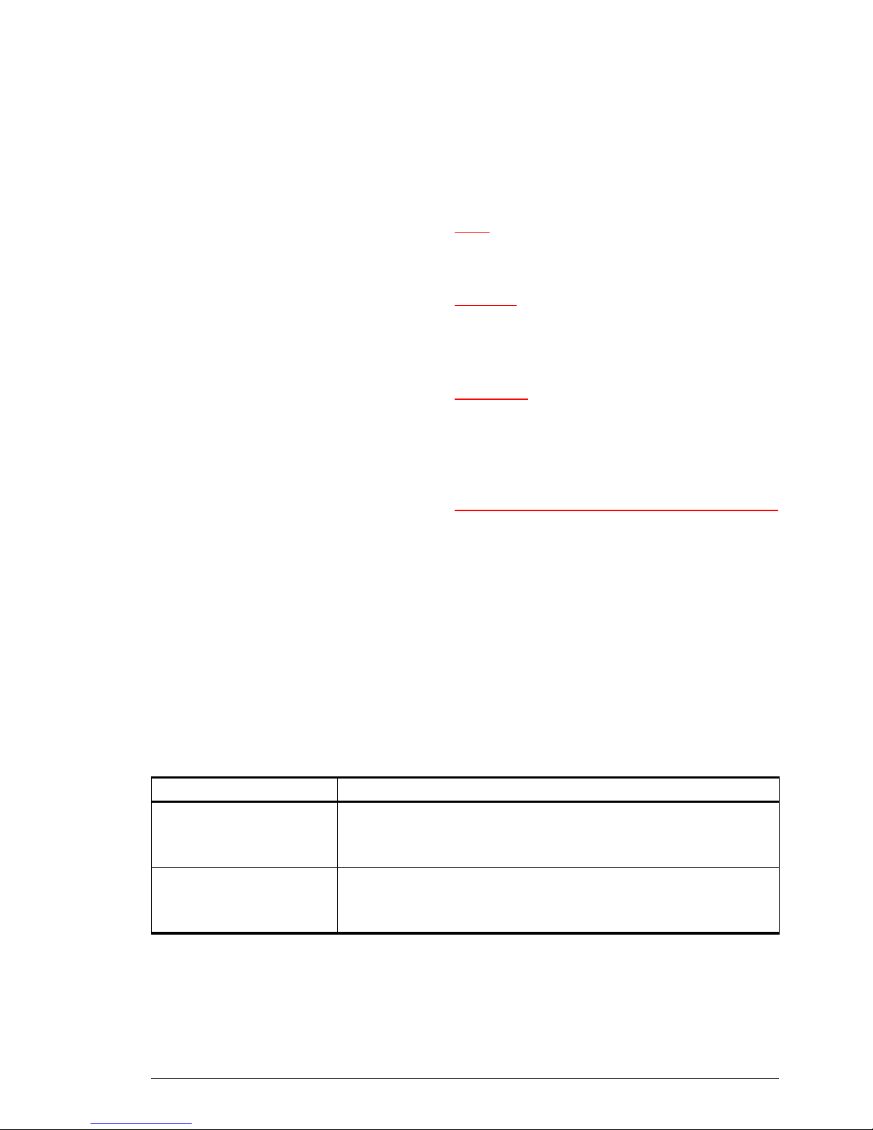
The system has a number of limitations:
• The unit is only suitable for use in Daikin direct expansion
systems.
• The unit is not suitable for cooling.
• The temperature control is less accurate than with water
or electric heating.
• The Daikin system has to be active at all times.
Other versions and intended use.
On request, versions can be supplied for other applications.
Warning:
wApplications other than those described above are
not considered to be an intended use. Biddle
assumes no responsibility for damage or injury
resulting from applications other than the intended
use. The intended use also implies observance of
and compliance with the instructions in this
manual.
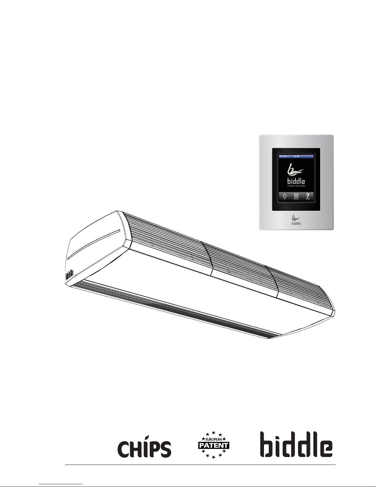
1.4.2 Function
The air curtain blows out a stream of heated air straight
down, thus achieving the following:
• The exchange of air between two rooms due to
temperature differences (convection) is stopped.
• The cold air entering across the floor due to draught is
heated.
Depending on the air curtains setting, the unit can also blow
unheated air.
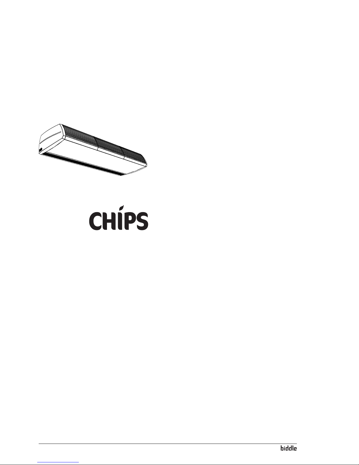
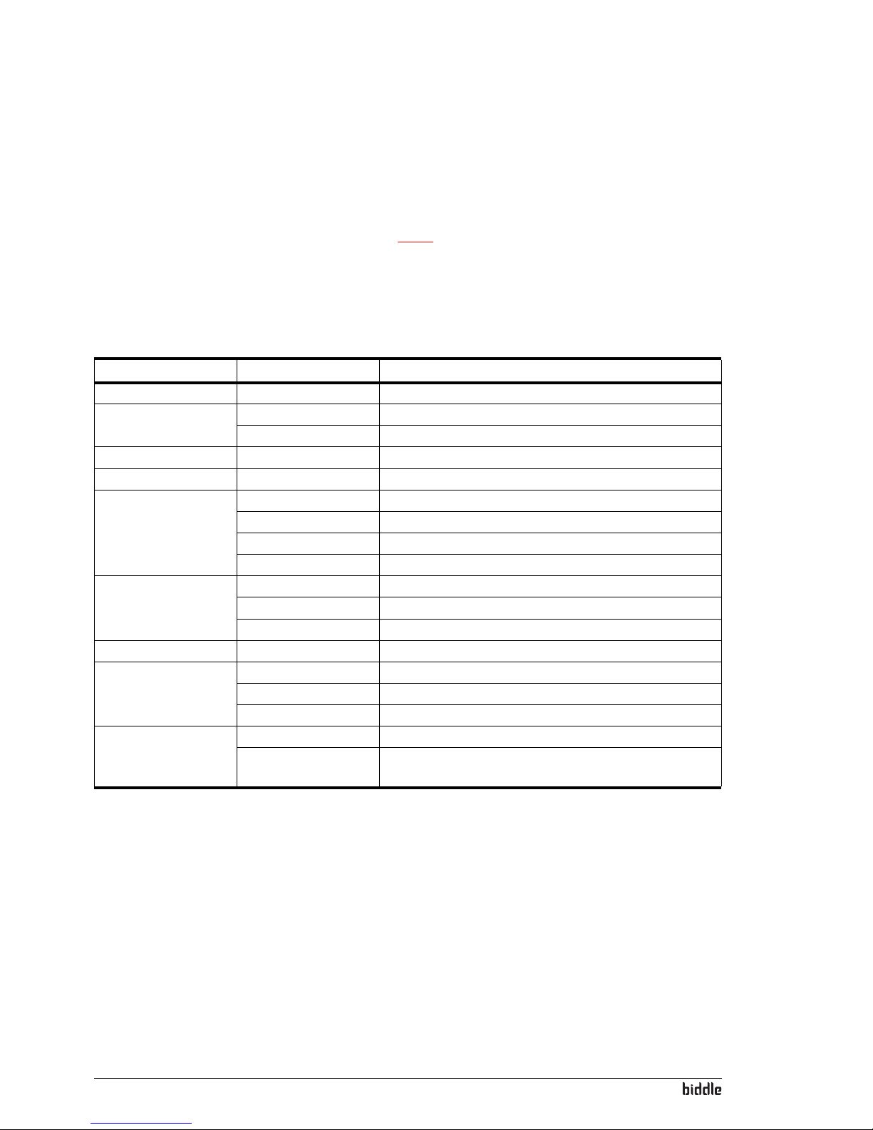
1.4.3 Models and type designations
Ta b l e 1-2 provides an overview of available models of the
comfort air curtain and the corresponding type designations.
Combined, the type designations constitute the type code, for
instance: CA2 S-100-W-F. Not every combination is available.
If some part of the manual applies to certain models only,
these will be indicated using the corresponding type
designation, for example:
-CA
2S, M: Models with capacity S or M;
-CA
2100: Models with discharge width 100;