Biddle Comfort Circle Series User manual

Manual
Cassette Air Heater/Cooler
Model Comfort Circle
a
Version of Guide: 1.0 R

2
Copyright and trademarks
All the information and drawings in this manual are the property of Biddle and may not be used (other than for the
actual operation of the device), photocopied, duplicated, translated and/or be brought to the attention of third
parties without Biddle’s prior written permission.
The name Biddle is a registered trademark.
Warranty and Liability
Please refer to Biddle’s Terms of Sales and Delivery for warranty and liability conditions.
Biddle excludes liability for consequential loss at all times and under all circumstances.
Liability for the contents of this manual
However much care might have been taken in ensuring the correctness and, where necessary, completeness of the
description of the relevant parts, Biddle disclaims all liability for damage resulting from any inaccuracies and/or
deficiencies in this manual.
Should you detect any errors or ambiguities in this manual then we would be pleased to hear from you: it helps us
to improve our documentation even further.
Biddle retains the right to change the specifications stated in this manual.
For more information
If you have any comments or questions about specific topics relating to this product, please do not hesitate to
contact Biddle.
Address for the UK:
Biddle Air Systems Ltd.
St. Mary’s Road
Nuneaton
Warwickshire CV11 5AU
United Kingdom
tel: 024 7638 4233
fax: 024 7637 3621
e-mail: sales@biddle-air.co.uk
internet: www.biddle-air.com
Address for other countries:
Biddle bv
P. O. B o x 1 5
NL-9288 ZG Kootstertille
The Netherlands
tel: +31 512 33 55 55
fax: +31 512 33 55 54
e-mail: export@biddle.nl
internet: www.biddle.info

MANUAL
Version: 1.0 (21-09-2005) 3
. . . Contents
Contents 3
1 Introduction 5
1.1 About this manual 5
1.2 How to use this manual 5
1.3 About the unit 7
1.4 Safety instructions 10
2 Installation 11
2.1 Safety instructions 11
2.2 Delivery check 11
2.3 General working method 11
2.4 Mounting the unit 12
2.5 Connecting the unit to the CH and CW systems 14
2.6 Connecting change-over 15
2.7 Connecting the condensate discharge (CC C) 17
2.8 Connecting a ventilation unit 18
2.9 Additional discharge connection 20
2.10 Connecting the unit to the power supply 21
2.11 Mounting the cover 21
2.12 Adjusting the discharge pattern 22
2.13 Installing the controller 23
2.14 Connecting the ventilation module VM-CC (accessory CC-V) 25
2.15 Connecting external controls to unit (optional) 25
2.16 Switching on and checking operation 28
3Settings 30
3.1 General 30
3.2 Settings 30
3.3 External controls 34
4 Operation 36
4.1 Switching on and off 36
4.2 Regulating the fan speed 37
4.3 Regulating the temperature 37
4.4 Regulating the ventilation 38
4.5 Locking the keys 38
4.6 Display messages 39
5Timer 41
5.1 Setting the current time 41
5.2 Setting the timer 42

COMFORT CIRCLE
4
6 Maintenance 43
6.1 Cleaning the unit 43
6.2 Cleaning the filter 43
6.3 Scheduled maintenance 45
6.4 Cleaning the condensate pump filter 45
7 Faults 46
7.1 Safety instructions 46
7.2 Resolving simple problems 46
7.3 Fault-finding by the installer 46
7.4 Fault messages in the controller 49
8Service 52
8.1 Safety instructions 52
8.2 Service menu 52
8.3 Resetting and reconfiguring the controller 52
8.4 Accessing the interior of the unit 53
8.5 Removing the main cover 55
8.6 Electronics module 55
8.7 Fuse 56
8.8 Venting the heat exchanger 57
8.9 Draining the heat exchanger 57
8.10 Setting the unit code 57
8.11 Composition of Biddle control cable 58
EC declaration of agreement 60

MANUAL INTRODUCTION
Version: 1.0 (21-09-2005) 5
1. . Introduction
1.1 About this manual
1.1.1 General
This manual describes the installation, operation and mainte-
nance of the Cassette Air Heater/Cooler, type Comfort Cir-
cle. The manual also provides instructions and information on
service works.
The manual provides important directions for the correct and
safe operation of the Comfort Circle as well as for the preven-
tion of accidents and damages.
So, read this manual carefully before starting to handle the
unit in any way.
1.2 How to use this manual
If you are unfamiliar with the Comfort Circle, read this man-
ual section by section.
If you are familiar with the device, you may use this manual as
a reference. Refer to the table of contents for looking up
information.
1.2.1 References in the manual
In this manual the following marginal symbols are used:
Note:
nDraws your attention to an important part of the text.
Read this part of the text thoroughly.
Caution:
cIf you do not carry out this procedure or action correctly,
you may damage the unit.
Follow the instructions strictly.

INTRODUCTION COMFORT CIRCLE
6
Warning:
wIf you do not carry out this procedure or action
correctly, you may cause material damage and/or
physical injury.
Follow the instructions strictly.
Danger:
dThis indicates actions which are not permitted.
Ignoring this warning may lead to serious damage
or accidents that may involve physical injury.
The action may be carried out only by technical
staff qualified to perform maintenance or repair
works.
1.2.2 Icons used on the unit and in the manual
The icons in Table 1-1 warn against potential risks or dangers.
The icons can be found opposite text discussing risk-entailing
operations. The same icons can also be found on the unit.
1.2.3 Related documentation
Besides this manual, the following document comes with the
unit:
• wiring diagram for installation and service purposes.
Table 1-1 Icons
ICON DESCRIPTION
Warning: You are entering an area which contains live components. Acces-
sible to qualified maintenance staff only.
Exert caution.
Warning: This surface or part can be hot. There is a risk of burns on con-
tact.
ê
ç

MANUAL INTRODUCTION
Version: 1.0 (21-09-2005) 7
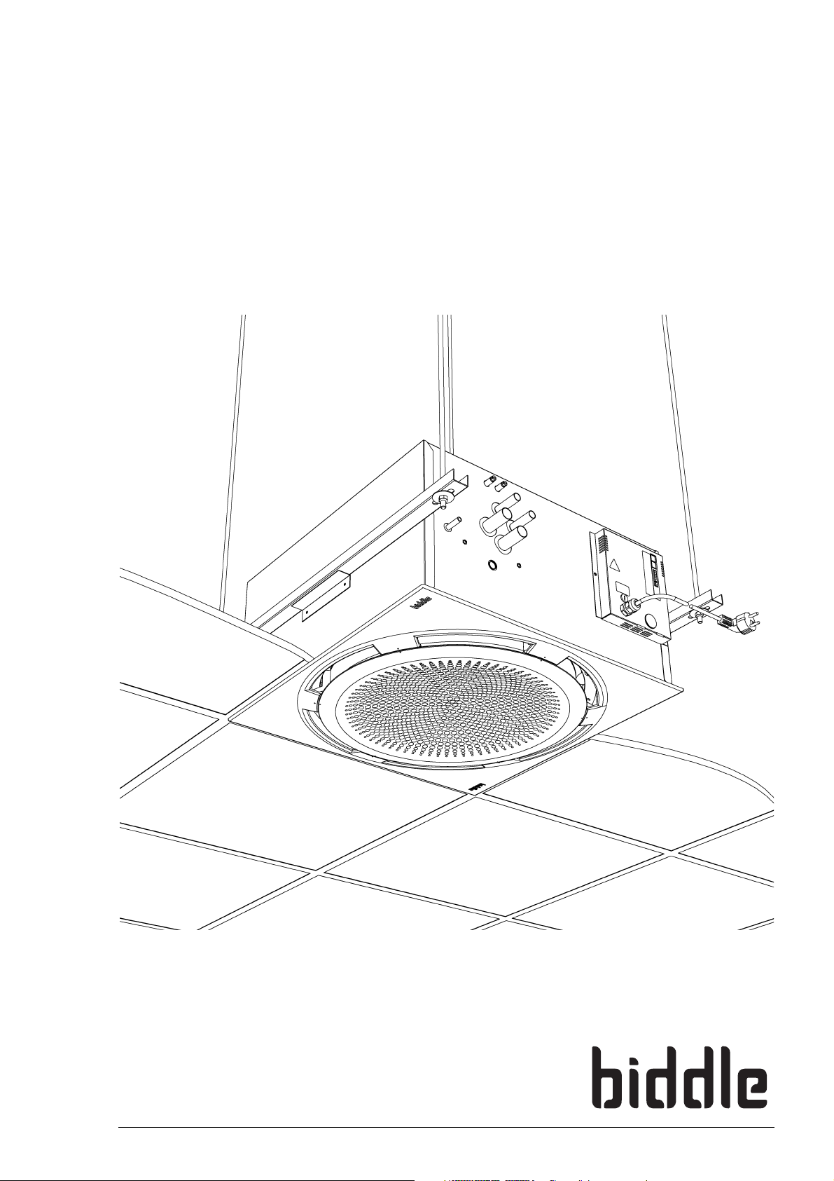
1.3 About the unit
1.3.1 Applications
The Comfort Circle is designed for heating, cooling and/or
ventilating rooms.
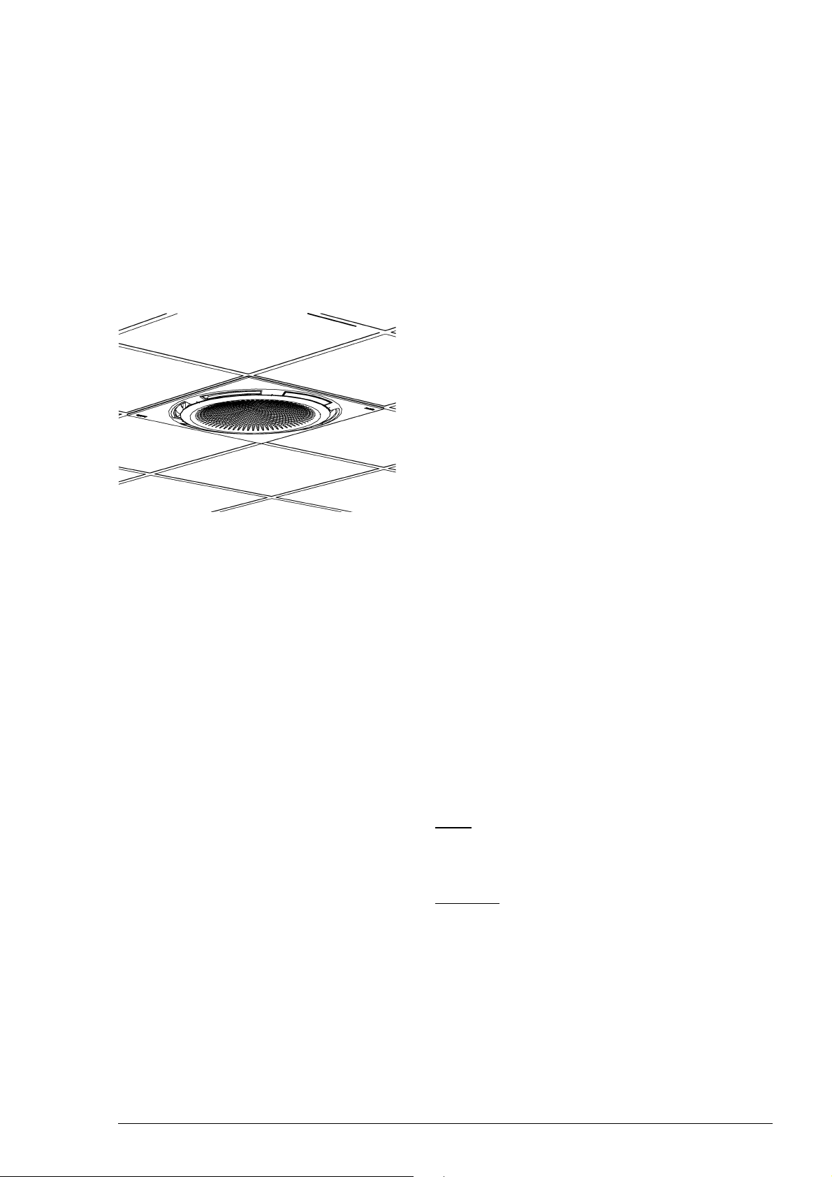
The model is designed for integration into suspended ceilings
but can be used in other ceilings as well. The unit is designed
to be mounted at a height of 2.0 to 3.5 m (from floor to dis-
charge grille).
The recirculation unit draws air from the room, heats or cools
it, and blows it back into the room.
The ventilation unit draws air from elsewhere, heats it, and
blows it into the room. This may be either unconditioned out-
side air or preconditioned air supplied by an A/C system. The
ventilation unit is available in two models: air intake from a
side, and air intake from above.
1.3.2 Working
The Comfort Circle blows out a flow of heated or cooled air,
creating a comfortable climate in the room.
The units that can both heat and cool have automatic dis-
charge angle control, which determines the discharge angle
based on the mode (cooling or heating). The other units have
a fixed discharge angle setting.
The units that can cool come standard with an integrated con-
densate draining pump.
The unit can be delivered with two types of control: a modu-
lating control and an On/Off control. The modulating control
controls both the fan speed and the discharge temperature to
reach the desired room temperature. The On/Off control
controls only the fan speed to achieve this goal. The ventila-
tion units come with modulating control only.
1.3.3 Models and type references
Table 1-2 provides an overview of available models of the
Comfort Circle and corresponding type references. Com-
bined, the type references constitute the type code, for
instance, CC 90-H2-M1.
CC V-H
CC V-V

INTRODUCTION COMFORT CIRCLE
8
If some part of the manual applies to certain models only,
these will be indicated using the corresponding type refer-
ence, for instance:
•CCM: units with modulating control;
•CCS: units with simple control;
•CCV: ventilation units;
•CCV-H: ventilation unit with horizontal connection.
Not all combinations are possible.
1.3.4 Type plate
The type plate can be found on the front side of the unit.
This manual refers to the following data on the type plate:
•Type: full type code of the unit;
•M: weight of the unit;
•pmax: maximum permissible operating pressure in the hot
water circuit (at 110 ºC);
•U, Imax, Pmotor and Pheating: the unit’s maximum load on the
electrical system.
Table 1-2 Type code explained
TYPE CODE ELEMENT REFERENCE MEANING
product series Comfort Circle general reference for the Comfort Circle
physical size 60 or 90 dimensions of the unit in the ceiling, 600x600mm and
900x900mm
ventilation V no reference: recirculation unit, V = ventilation unit
heat exchanger H2, H3 water-heated, 2 or 3 rows
C2, C3 water-cooled, 2 or 3 rows
H1/C2 water-heated and -cooled, 1 and 2 rows, resp.
control Mmodulating control
SOn/Off control
discharge angle adjust-
ment
0 or 1 without or with automatic angle adjustment
ventilation connection H or V horizontal (CC V-H) or vertical (CC V-V) ventilation
connection
Type CC 60-H2-M1
Code U 230 V 1N~ 50 Hz
Biddle bv
Markowei 4
NL-9288 HA Kootstertille Nº 123456/1-1 05-53 Imax L1 xxx A
Imax L2 -
M30kg I
max L3 -
Medium LPHW Pmotor xxx kW
pmax 1400 kPa Pheating -
xxx

MANUAL INTRODUCTION
Version: 1.0 (21-09-2005) 9
1.3.5 What’s in the box
The unit comes in a box, which contains the following compo-
nents:
• unit 1
•cover2;
• 2 suspension profiles 3;
• 2 blind plates 4with fixing screws to adjust the discharge
pattern;
• 1 or 2 valves 5with servomotors (only for units with
modulating control);
• external drip tray 6with fixing screws (only for cooling
units).
1.3.6 Components and accessories
1.3.7 Components
The following components are delivered separately but are
always required:
• controller 7;
• control cable 8, available in various lengths.
Accessories
The following accessories are available as options:
• low-limit sensor for change-over detection;
• saddle piece for additional discharge connection;
• ventilation module for coupling to exhaust fan.
1.3.8 Third-party deliverables
The following components are needed for the proper installa-
tion of the ventilation units:
• wall or roof grates;
• air valves;
• air valve servomotors;
• air filters;
•insulatedducts.
These parts are not delivered by Biddle and should be pur-
chased from other suppliers.
1
2
3
4
5
6
7
8

INTRODUCTION COMFORT CIRCLE
10
1.4 Safety instructions
1.4.1 Operation
Warning:
wDo not put any objects in the in- and outlets.
Warning:
wDo not block the in- and outlets.
Warning:
wThe upper surface of the unit becomes hot during
operation.
1.4.2 Installation, maintenance and service
Danger:
dThe unit may be opened by qualified technical staff
only.
Warning:
wBefore opening the unit, do the following:
1. Switch the unit off using the controller.
2. Wait until the fans have stopped.
3. Allow the unit to cool down.
The heat exchanger can get very hot.
4. Disconnect the power supply (pull plug from socket or
move isolation switch, if any, to Off).
5. Close CH supply (if possible).
Warning:
wThe fins of the heat exchanger are sharp.
ç
ê
ç

MANUAL INSTALLATION
Version: 1.0 (22-09-2005) 11
2. . Installation
2.1 Safety instructions
Danger:
dInstallation works on the unit may be performed by
qualified technical staff only.
Warning:
wBefore opening the unit, follow the safety instruc-
tions in section 1.4.
2.2 Delivery check
1. Check the unit and its packaging for correct delivery.
Immediately report any transit damage to the driver and
the supplier.
2. Make sure that all components have been delivered (see
section 1.3.5). Immediately report any defects to the sup-
plier.
2.3 General working method
Order of working
Biddle recommends the following working method for install-
ing the Comfort Circle:
1. Suspend the unit (section 2.4).
2. Connect the unit to the CH system (section 2.5).
3. Connect the condensate discharge (CC C only,
section 2.7).
4. Connect the unit to the air ducts (CC V only, section 2.8).
5. Connect the unit to the power supply (section 2.10).
6. Install the controller and (any optional) connections to
external controls (section 2.13).
7. Turn on the power supply and check the working of the
unit (section 2.16).

INSTALLATION COMFORT CIRCLE
12
General instructions
Some parts of this section are applicable only to certain mod-
els. Where this is the case, it will be indicated. If no specific
model is referred to, the description applies to all models.
Note:
nMake sure you perform all installation operations that are
required for your unit.
Check the type plate. Refer to section 1.3.4 if you are not
sure about the model or type of your unit.
Note:
nProtect the unit from damage and ingress of dust, cement,
etc. throughout the installation. You can, for instance, use
the packaging for protection.
2.4 Mounting the unit
2.4.1 Positioning the unit
• Make sure that the structure from which the unit is about
to be suspended can hold the weight of the unit. The
weight is specified on the type plate (see section 1.3.4).
• Ensure the following:
- Position the unit between the ceiling profiles.
- Give heed to the unit’s orientation in the room (it is
possible to adapt the discharge pattern to the room –
see section 2.12).
- The maximum mounting height for the unit is 3.5 m. (,
measured from floor to ceiling).
Caution:
cProvide for an inspection hatch in the ceiling if the Com-
fort Circle is not fitted in a suspended ceiling.
Warning:
wThe minimum mounting height is 2.0 m.
Note:
nMounting the unit above the maximum height may affect
the proper working of the unit.

MANUAL INSTALLATION
Version: 1.0 (22-09-2005) 13
2.4.2 Suspending and securing the unit
1. Mount Flamco rails 1and fit threaded rods M8 2accord-
ing to the dimensions in Table 2-1. Make sure the threaded
rods are perpendicular.
2. Mount the suspension profiles 3 to the threaded rods.
3. Hook the unit into the suspension profiles.
4. You can still change the position of the unit somewhat by
moving it in the suspension profiles and Flamco rails.
5. Secure the suspension on both sides using the securing
brackets 4.
6. Bring the underside of the unit in line with the T-beams of
the ceiling.
Caution:
cEnsure that the unit is level.
Warning:
wThe unit may come down if you do not secure the
suspension.
1
2
3
4
Table 2-1 Dimensions for suspending the unit
REFERENCE TYPE DIMENSION
aall models as needed
ball models 670 - 750
cCC 60 600
CC 90 900
a
c
b

INSTALLATION COMFORT CIRCLE
14
2.5 Connecting the unit to the CH and CW systems
2.5.1 Particulars
Caution:
cThe supply and return pipes of the CH and CW systems
must be connected to the appropriate corresponding con-
nections 1. The directions are indicated on the unit by
means of arrows.
Warning:
wMaximum water temperature ranges for the CC S:
- CC H2-S: 80/60°C
- CC H3-S: 70/50°C
Warning:
wUse only compression fittings for connecting the
unit to the system. Table 2-2 lists the diameters of
the compression fittings per unit type.
Warning:
wPrevent the pipes from twisting.
Caution:
cBiddle recommends to include, close to the unit, a shut-off
valve and a relief valve in both pipes.
The maximum permissible operating pressure of the hot
water circuit is specified on the type plate (see section
1.3.4). This pressure applies at a water temperature of
110 ºC.
2.5.2 Units without water side control CC S
1. Connect the unit to the CH system.
2. Fill and bleed the system.
3. Check the connections for leaks.
Table 2-2 Diameters of compression fittings.
TYPE COMPRESSION FITTING
CC 60-H2, C2, H3, C3 ø22mm
CC 60-H1/C2 H: ø15mm - C: ø22mm
CC 90-H2, C2, H3, C3 ø22mm
CC 90-H1/C2 H: ø15mm - C: ø22mm

MANUAL INSTALLATION
Version: 1.0 (22-09-2005) 15
2.5.3 Units with water side control CC M
1. Connect the unit and the valve 1to the CH system
according to the opposite diagram.
1. Connect the heating valve to connector 1(~) according
to the wiring diagram.
2. Connect the cooling valve to connector 2(*) according
to the wiring diagram.
3. Fill and bleed the system.
4. Check the connections for leaks.
2.6 Connecting change-over
2.6.1 Introduction
If a unit is integrated into a change-over system, the control-
ler must know whether the system is supplying hot or cold
water. There are three options to achieve this:
1. Low-limit-temperature sensor (option) (see section 2.6.2).
2. Signal to the unit’s input (see section2.6.3).
3. Signal to the unit’s output (see section2.6.4).
1
1
2
~
*
*I~
change-over

INSTALLATION COMFORT CIRCLE
16
2.6.2 Connecting the low-limit-temperature sensor
1. Mount the low-limit-temperature sensor 1onto the sys-
tem’s supply pipe.
2. Open the electronics module 2(see section 8.6).
3. Make crosswise cuts in grommet 3.
4. Lead the sensor cable through the grommet.
5. Connect the sensor to terminal X360 4on the PCB.
6. Close the electronics module.
7. Set function 79 to value 1 (see section 3.2.2).
The unit now follows the mode of the system.
2.6.3 Signal to the unit’s input
If contact is made to the unit’s input, the unit will switch from
heating mode to cooling mode (see table 3-1, function 90).
1. Connect the signal cable to the unit’s input 1(see
section 2.15.7).
2. Set function 90 to value 1 (see section 3.2.2).
If a signal is sent to the input, the unit will switch from
heating mode to cooling mode.
2.6.4 Signal to the unit’s output
Both a CH and a CW machine can be controlled via the unit’s
outputs. You can connect the CH and CW machines to an
output either separately or linked. The unit thus determines
whether the change-over system will cool or heat.
1
2
3
43
1

MANUAL INSTALLATION
Version: 1.0 (22-09-2005) 17
Connecting CH and CW separately
1. Connect the CH signal cable to output O1 1.
2. Connect the cold water machine signal cable to
output O2 2.
3. Set function 91 (output O1 function) to value 55 (heating
demand).
4. Set function 91.5 to value 0 (make contact ).
5. Set function 92 (output O2 function) to value 56 (cooling
demand).
6. Set function 92.5 to value 0 (make contact ).
Connecting CH and CW together
1. Connect the signal cable of the change-over system to out-
put O1 1.
2. Set function 91 (output O1 function) to value 57.
3. Set function 91.5 to value 0 (make contact ).
If the unit switches from heating mode to cooling mode, a
signal is sent to the output.
2.7 Connecting the condensate discharge (CC C)
The units with cooling come standard with a condensate
draining pump. The condensate is drained from the unit
through a flexible hose.
1. Install a sewer connection incl. stink trap for the discharge
of condensate.
2. Connect the discharge hose 1to the drain pipe.
In doing so, pay attention to this:
- For proper condensate discharge, the drain pipe must
be sloping (>2%).
- Avoid kinks in the discharge hose.
- Above the ceiling, the discharge hose must be insulated.
3. Mount the external drip tray 2using the supplied
screws 3.
1
2
1
>2%
1
2
3
3

INSTALLATION COMFORT CIRCLE
18
2.8 Connecting a ventilation unit
2.8.1 Connecting air intake ducts (CC V)
The ventilation units are fit for drawing air from elsewhere to
discharge it into the room. This air can be either filtered out-
side air or preconditioned air.
It is possible to open and close air valves with the unit.
Warning:
wFiltered air 1 must be supplied to the ventilation
unit.
Note:
nTo prevent draught when the unit is switched off, Biddle
recommends to include air valves 2in the air intake ducts.
1. Connect insulated ducts with a diameter according to
table 2-3 to the unit.
2. Connect the air valve servomotors to the unit according
to the wiring diagram.
2.8.2 Air valve control
There are two options for controlling air valves:
• via the 0-10VDC output on the PCB for the control of
0-10VDC servomotors.
• via a signal to output O3 (24V~1A).
CC V-H
12
CC V-V
1
2
Table 2-3 Diameters of ducts
TYPE DUCT DIAMETER NUMBER
CC 60-V-H ø200mm 2
CC 60-V-V ø280mm 1
CC 90-V-H ø200mm 4
CC 90-V-V ø400mm 1

MANUAL INSTALLATION
Version: 1.0 (22-09-2005) 19
0-10VDC output
1. Open the electronics module 1.
2. Make crosswise cuts in grommet 2.
3. Lead the wiring through the grommet.
4. Connect the wiring to terminal X340 3.
5. Set function 85 to value 1 (enabled).
6. Set functions 86, 87 and 88 to value 99.
This makes that the air valves are always opened fully
when the unit is in operation.
Caution:
cValues other than 99 make that the air valves are not
opened fully, which will affect the operation of the unit.
Signal to output O3
For ventilation units, the function of output O3 is set to the
default value 70, with contact being made to the output when
the fans are rotating. If the discharge temperature falls below
6°C, the contact will be broken and the ventilation units will
be switched off.
This signal can be used either to directly control suitable ser-
vomotors or to control a 24V relay controlling the servomo-
tors.
1. Connect the wiring to output O3 1.
2.8.3 Servomotor power supply
Power supply to the servomotors of the air valves can be
obtained either via terminal X230 2on the electronics mod-
ule or via connection X340 3 (0-10VDC output) on the PCB.
Caution:
cThe maximum load is 24V~, max. 5VA.
1
2
3
1
2
3

INSTALLATION COMFORT CIRCLE
20
2.9 Additional discharge connection
The CC has a prepunched hole in the casing. A ø160 mm air
duct can be mounted to this hole, so that discharge air can be
led to an additional air grille.
Caution:
cIf the additional discharge is located in a room other than
where the unit is, an air return path 1, such as a wall or
door grate or a shortened door, must be provided for.
1. Cut the connections of the prepunched hole 2.
2. Cut the insulation material.
Caution:
cIn doing so, do not damage the heat exchanger.
3. Press the saddle piece 3onto the hole.
4. Mount the ductwork and the discharge grille.
Caution:
cWhen using ducts, take the following into account:
- Use ducts that are designed for a continuous opera-
tional temperature of 80°C.
- For cooling units, use insulated ducts.
5. Mount the two supplied blind plates 4into the discharge
grille, on the side of the air connection (see section 2.12).
Caution:
cThe blind plates must be mounted for proper operation of
the unit.
1
23
44
4
This manual suits for next models
10
Table of contents
Other Biddle Air Conditioner manuals