Biddle SF User manual

Manual
Comfort Air Curtain
Model SF
a
Version of guide: 4.0 R

2
Copyright and trademarks
All the information and drawings in this manual are the property of Biddle and may not be used (other than for the
actual operation of the device), photocopied, duplicated, translated and/or be brought to the attention of third
parties without Biddle’s prior written permission.
The name Biddle is a registered trademark.
Warranty and Liability
Please refer to Biddle’s Terms of Sales and Delivery for warranty and liability conditions.
Biddle excludes liability for consequential loss at all times and under all circumstances.
Liability for the contents of this guide
However much care might have been taken in ensuring the correctness and, where necessary, completeness of the
description of the relevant parts, Biddle disclaims all liability for damage resulting from any inaccuracies and/or
deficiencies in this guide.
Should you detect any errors or ambiguities in this guide then we would be pleased to hear from you: it helps us to
improve our documentation even further.
Biddle retains the right to change the specifications stated in this guide.
For more information
If you have any comments or questions about specific topics relating to this product, please do not hesitate to
contact Biddle.
Biddle bv
P. O. B o x 1 5
NL-9288 ZG Kootstertille
The Netherlands
tel: +31 512 33 55 55
fax: +31 512 33 55 54
e-mail: export@biddle.nl
internet: www.biddle.info

MANUAL
Version: 4.0 (09-10-2008) 3
. . . Table of contents
1 Introduction 5
1.1 About this manual 5
1.1.1 General 5
1.2 How to use this manual 5
1.2.1 References in the manual 5
1.2.2 Symbols used on the unit and in the manual 6
1.2.3 Related documentation 6
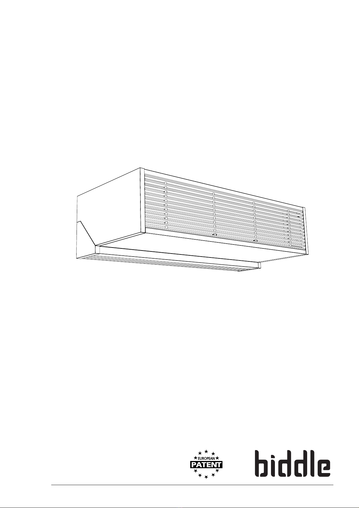
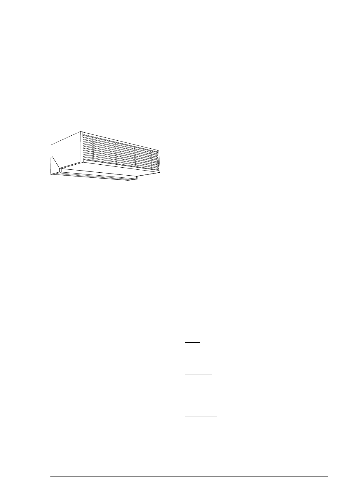
1.3 About the unit 6
1.3.1 Applications 6
1.3.2 Working 7
1.3.3 Models and type references 7
1.3.4 Type plate 8
1.3.5 Components and accessories 8
1.4 Safety instructions 9
1.4.1 Operation 9
1.4.2 Installation, maintenance and service 9
2 Installation 10
2.1 Safety instructions 10
2.2 Delivery check 10
2.3 General working method 10
2.4 Mounting the unit 11
2.4.1 Positioning the unit 11
2.4.2 Suspending and securing the unit 12
2.5 Connecting the unit to the central heating system 13
2.5.1 Particulars 13
2.5.2 Units without water-side control 13
2.5.3 Units with water-side control 13
2.6 Connecting the unit to the power supply 15
2.6.1 Connecting water-heated models 15
2.6.2 Connecting electrically-heated models 15
2.7 Setting a unit as master (SFi, optional) 17
2.7.1 Working 17
2.7.2 Setting the unit 17
2.8 Connecting external controls (SFi, optional) 18
2.8.1 Input for external control 18
2.8.2 Output for fault signal indication 18
2.9 Installing the controller 19
2.9.1 Mounting and connecting the touchpad controller (SFi)19
2.9.2 Mounting and connecting the three-speed switch (SFs)20
2.10 Integrating the unit 21
2.10.1 Mounting the telescopic discharge grille 21
2.10.2 Mounting the integrated intake grille (option) 21
2.11 Applying the edge finishing 22
2.12 Switching On and checking operation 22

COMFORT AIR CURTAIN
4
3 Operation 23
3.1 Three-speed switch (SFs)23
3.1.1 Setting the air curtain strength 23
3.2 Touchpad controller (SFi)23
3.2.1 Switching the air curtain On and Off 24
3.2.2 Setting the air curtain strength 24
3.2.3 Enabling or disabling heating 24
3.2.4 Enabling or disabling Automatic restart 25
4 Maintenance 26
4.1 Cleaning the unit 26
4.2 Scheduled maintenance 26
5 Faults 27
5.1 Safety instructions 27
5.2 Fault-finding by the user 27
5.3 Fault-finding by the installer 27
6Service 32
6.1 Safety instructions 32
6.2 Access to the interior of the unit 32
6.3 PCB (SFi) 33
6.3.1 Introduction 33
6.3.2 Removing the PCB (SFi W) 33
6.3.3 Removing the PCB (SFi E) 33
6.3.4 DIP switches on the PCB 34
6.4 Fuses (SFi) 34
6.5 Resetting the high-limit thermostat (SFiE) 34
6.6 Composition of Biddle control cable 35
Declaration of conformity 36

MANUAL INTRODUCTION
Version: 4.0 (09-10-2008) 5
1. . Introduction
1.1 About this manual
1.1.1 General
This manual describes the installation, operation and mainte-
nance of the Comfort Air Curtain model SF. The manual also
provides instructions and information on service works.
The manual provides important directions for the correct and
safe operation of the air curtain, and for the prevention of
accidents and damages.
So, read this manual carefully before starting to handle the unit
in any way.
1.2 How to use this manual
If you are unfamiliar with the Comfort Air Curtain, read this
manual section by section.
If you are familiar with the device, you may use this manual as
a reference. Refer to the table of contents for looking up
information.
1.2.1 References in the manual
In this manual the following marginal symbols are used:
Note:
nDraws your attention to an important part of the text.
Read this part of the text carefully.
Caution:
cIf you do not perform this procedure or action correctly,
you may damage the device.
Follow the instructions carefully.
Warning:
wIf you do not perform this procedure or action cor-
rectly, you may cause damage and/or bodily injury.
Follow the instructions strictly.

INTRODUCTION COMFORT AIR CURTAIN
6
Danger:
dThis indicates actions which are not permitted.
Ignoring this warning may lead to serious damage
or accidents which may involve bodily injury.
The action may be carried out only by qualified
staff performing maintenance or repair works.
1.2.2 Symbols used on the unit and in the manual
The symbols in Table 1-1 warn against potential risks and/or
dangers. The symbols can be found opposite the text discuss-
ing risk-entailing operations. The same icons will also be found
on the device.
1.2.3 Related documentation
Besides this manual, the following document comes with the
unit:
• wiring diagram for installation and service purposes.
1.3 About the unit
1.3.1 Applications
The comfort air curtain is designed to separate the climates
between two rooms. The unit is installed above the doorway,
across its full width.
By installing multiple units side by side, openings of unlimited
width can be screened off in steps of 50 cm.
The model is designed for free, visible installation above doors
as well as for integration into coves or suspended ceilings.
Table 1-1 Symbols
ICON DESCRIPTION
Warning: You are entering an area which contains ‘live’ components.
Accessible to qualified maintenance staff only.
Exert caution.
Warning: This surface or part can be hot. There is a risk of burns on con-
tact.
ê
ç

MANUAL INTRODUCTION
Version: 4.0 (09-10-2008) 7
1.3.2 Working
The air curtain blows a stream of either heated or unheated
air straight down, achieving the following:
• The exchange of air between two rooms due to tempera-
ture differences (convection) is stopped.
•For heated air: the air entering across the floor due to
draught is heated.
•For unheated air: warm outside air is kept outside to sup-
port the air-conditioning in the room.
The air curtain is designed such that there is no need for air
filters.
1.3.3 Models and type references
Table 1-2 on page 7 provides an overview of the available
models of the comfort air curtain and the corresponding type
references. Combined, the type references constitute the type
code, for instance: SFiSP-100-W-F.
If some part of the manual applies to certain models only,
these will be indicated using the corresponding type refer-
ence, for instance:
-SFi: models with touchpad controller
-SFs: models with three-speed switch
-SFW:water-heatedmodels
- SF E: electrically-heated models
- SF A: models without heating (ambient)
Table 1-2 Type code explained
TYPE CODE ELE-
MENT REFERENCE MEANING
product series SF general reference for the series
control ior stouchpad controller or three-speed switch
capacity SP or HP installation height 2.20-2.40 m or 2.80-3.00 m
unit length 100, 150 of 200 unit length in cm
heating Wwater heating
Eelectric heating
Awithout heating (ambient)
mounting method Ffree-hanging model, also fit as recessed model

INTRODUCTION COMFORT AIR CURTAIN
8
1.3.4 Type plate
The type plate can be found on the top of the unit.
This manual refers to the following data on the type plate:
•Type: full type code of the unit.
•M: weight of the unit.
•pmax: maximum permissible operating pressure in the hot
water circuit (at 110 ºC).
•U, Imax, Pmotor and Pheating: maximum load on the electrical
system by the unit.
1.3.5 Components and accessories
Components
The following components are delivered separately but are
always required:
• touchpad controller or three-speed switch.
Accessories
The following accessories are available as options:
• water-side control for connection with touchpad control-
ler.
• water-side control for fixed discharge temperature.
• Biddle control cable, available in various lengths, to link
multiple units to one single touchpad controller.
• door contact switch.
• suspended ceiling finishing kit.
• Telescopic discharge grille for recessed model.
• Intake grille for recessed model.
Type SFsHP-200-W-F
Code U 230 V 1N~ 50 Hz
Biddle bv
Markowei 4
NL-9288 HA Kootstertille Nº 123456/1-1 04-53 Imax L1 6.18 A
Imax L2 -
M66kg I
max L3 -
Medium LPHW Pmotor 1.42 kW
pmax 1400 kPa Pheating -

MANUAL INTRODUCTION
Version: 4.0 (09-10-2008) 9
1.4 Safety instructions
1.4.1 Operation
Warning:
wIt is not allowed to install air filters in the air cur-
tain.
Warning:
wDo not put any objects in the in- and outlets.
Warning:
wDo not block the in- and outlets.
Warning:
wThe upper surface of the unit becomes hot during
operation.
1.4.2 Installation, maintenance and service
Danger:
dThe unit may be opened by qualified technical staff
only.
Warning:
wPerform the following actions before opening the
unit:
1. Switch the unit Off using the controller.
2. Wait until the fans have stopped.
3. Allow the unit to cool down.
The heat exchanger or, as the case may be, the heating ele-
ments can get very hot. Moreover, the fans may keep on
rotating for a while.
4. Disconnect the power supply (pull plug from socket or
move isolation switch, if any, to Off).
5. For water-heated models: close central heating supply (if pos-
sible).
Warning:
wThe fins of the heat exchanger are sharp.
ç
ê
ç

INSTALLATION COMFORT AIR CURTAIN
10
2. . Installation
2.1 Safety instructions
Danger:
dInstallation works on the unit may be performed by
qualified technical staff only.
Warning:
wBefore opening the unit, follow the safety instruc-
tions in section 1.4.
2.2 Delivery check
1. Check the unit and its packaging for correct delivery.
Immediately report any transport damage to the driver
concerned and to the supplier.
2. Make sure that all components have been supplied. Imme-
diately report any defects to the supplier.
2.3 General working method
Working method
Biddle recommends the following working method for the
installation of the comfort air curtain:
1. Mount the unit (section 2.4).
2. For water-heated models: connect the unit to the central
heating system (section 2.5).
3. Connect the unit to the power supply (section 2.6).
4. Install the controller and (any optional) connections to
external controls (sections 2.7, 2.8, and 2.9).
5. Finish the unit (section 2.11).
6. Turn on the power supply and check the working of the
unit (section 2.12).

MANUAL INSTALLATION
Version: 4.0 (09-10-2008) 11
General instructions
Some parts of this section are applicable only to certain
models. Where this is the case, it will be indicated. If no spe-
cific model is referred to, the description applies to all models.
Note:
nMake sure you perform all installation operations that are
required for your unit.
Check the type plate and refer to section1.3.3 if you are
not sure about the model or type of your unit.
Note:
nProtect the unit from damage and ingress of dust, cement,
etc. throughout the installation. You can, for instance, use
the packaging for protection.
2.4 Mounting the unit
2.4.1 Positioning the unit
• Make sure that the structure from which the unit is about
to be suspended can bear the weight of the unit. The
weight is specified on the type plate (see section 1.3.4).
• Note the following dimensions:
- The unit must be at least as wide as the doorway
(dimension b).
- Position the unit as near to the doorway as possible.
- The maximum mounting height of the unit (dimension
h, measured from the floor to the discharge grille)
depends on the unit type (see Table 2-1).
Warning:
wThe minimum mounting height (dimension h) is
1.8 m.
Warning:
wThe top of the unit may get hot. Mount the unit at
a minimum of 25 mm from the ceiling (dimension x
on page 11).
bh
x
ç

INSTALLATION COMFORT AIR CURTAIN
12
Note:
nMounting the unit at a height exceeding the maximum
height may affect the proper working of the unit.
2.4.2 Suspending and securing the unit
1. Fix four M8 threaded rods according to the dimensions in
Table 2-2. Make sure that the threaded rods are perpendic-
ular.
2. Apply a lock nut 1to each threaded rod.
3. Fix the unit to the threaded rods.
4. Secure the unit to the suspension rods by tightening the
lock nuts 1.
Table 2-1 Mounting height of unit
TYPE MAXIMUM MOUNTING HEIGHT H
SF SP 2.40 m
SF HP 3.00 m
• These heights apply under normal circumstances. If not
sure, ask Biddle for advice on the correct height.
1
Table 2-2 Dimensions for suspending the unit
REFERENCE TYPE DIMENSIONS
aall models as needed
ball models 35 mm
call models 228 mm
dSF 100 896 mm
SF 150 1396 mm
SF 200 1896 mm
a
bcd

MANUAL INSTALLATION
Version: 4.0 (09-10-2008) 13
2.5 Connecting the unit to the central heating system
Water-heated models only
2.5.1 Particulars
Caution:
cThe supply and return pipes of the central heating system
must be connected to the appropriate corresponding
connections 1(G1"). The directions are indicated on the
unit using arrows.
Caution:
cWhen connecting the pipes, hold the connections 1in
place using pliers.
Caution:
cBiddle recommends the inclusion of a valve and a relief
valve in both pipes, near the unit.
The maximum permissible operating pressure in the hot
water circuit is specified on the type plate (see
section 1.3.4). This pressure applies at a water tempera-
ture of 110 ºC.
2.5.2 Units without water-side control
1. Connect the unit to the central heating system.
2. Fill and bleed the system.
3. Check the connections for leaks.
2.5.3 Units with water-side control
Control for connection with touchpad controller.
1. Open the unit (see section 6.2).
2. Connect the unit and valve to the central heating system
according to the opposite diagram.
1
1

INSTALLATION COMFORT AIR CURTAIN
14
3. Connect the valve to connector 1according to the wir-
ing diagram.
4. Close the unit.
5. Manually open the valve using handle 2.
6. Fill and bleed the system.
7. Check the connections for leaks.
8. Place handle 2back to its starting position.
Control for fixed discharge temperature
1. Open the unit (see section 6.2)
2. Connect the unit and valve to the central heating system
according to the opposite diagrams.
3. Mount the thermostatic control to the valve.
4. Make crosswise cuts in grommet 2.
5. Insert sensor 1into the unit.
1
2
1
2

MANUAL INSTALLATION
Version: 4.0 (09-10-2008) 15
6. Mount sensor 1to the heat exchanger using the spring
clips 3.
7. Close the unit.
8. Set the thermostatic control to the desired discharge tem-
perature.
Note:
nBiddle recommends a discharge temperature of 35°C.
9. Fill and bleed the system.
10. Check the connections for leaks.
2.6 Connecting the unit to the power supply
2.6.1 Connecting water-heated models
1. Ensure that an (earthed) power point is available at a maxi-
mum of 1.5 m from the right-hand side of the unit.
Caution:
cDo NOT yet switch the mains supply on.
Warning:
wThe unit must be earthed.
2.6.2 Connecting electrically-heated models
Danger:
dDo not perform the connection work unless you
are qualified to work with three-phase current.
Particulars
• Connect the unit to the power supply with a 5-core cable
(not supplied). The maximum load data are specified on
the type plate (see section 1.3.4).
13
1
3

INSTALLATION COMFORT AIR CURTAIN
16
• An isolation switch (not supplied) must be fitted between
the unit and the power supply. This switch must:
- be all-pole;
- have a minimum contact clearance of 3 mm;
- be positioned within 4 m from the right side of the unit.
Warning:
wThe unit must NOT be switchable using the power
supply cable – use the touchpad controller for that.
Warning:
wThe unit must be earthed.
Warning:
wConnect the unit in accordance with the applicable
local requirements.
Performing the connection
Warning:
wMake sure that the power supply you are working
on is switched off.
1. Fit the isolation switch and connect it to the power supply.
2. Open the unit (see section 6.2).
3. Lead the mains supply cable through the cable gland 1.
4. Connect the cable to the terminal 2in the unit according
to the wiring diagram.
5. Put back and screw down the inspection panel and grille.
6. Connect the mains supply cable to the isolation switch.
Caution:
cDo NOT yet switch the mains supply on.
123N
contact clearance
RS TN
1
2

MANUAL INSTALLATION
Version: 4.0 (09-10-2008) 17
2.7 Setting a unit as master (SFi, optional)
With multiple units operated from one control panel
only
2.7.1 Working
On delivery, each unit comes set as equal. If you apply multi-
ple units with one control panel, the units work independently:
• If you connect an external control (see section 2.8.1), only
the unit to which it is connected to will respond to it.
• With the automatic temperature control (see section
3.2.3), the temperature is regulated independently in each
unit.
You may choose to set one unit as master. By this, the work-
ing of the units will be linked:
• If you connect an external control to the master unit, the
other units will respond to it in the same way.
• With the automatic temperature control, all units are regu-
lated from the master unit.
2.7.2 Setting the unit
With the unit that is to be set as master:
1. Open the unit. (see section 6.2)
2. Take out the PCB if necessary (see section 6.3)
3. Set DIP switch no. 3 on the PCB into the ’ON’ position.
Warning:
wNEVER change the settings of the other DIP
switches.
4. Close the unit.
With the other units, leave this setting unchanged.

INSTALLATION COMFORT AIR CURTAIN
18
2.8 Connecting external controls (SFi, optional)
2.8.1 Input for external control
To the input, you may connect a door contact switch and/or a
BMS system.
The connector is located in the top of the unit. It comes with
a bridge in it on delivery. The connector is wired to the PCB
(connector INHIBIT).
The input is fit for potential-free switch contacts. It is oper-
ated as follows:
•contact closed (or with a bridge): The unit works normally.
•contact open: The unit remains switched off.
•with a resistance across the contact (3,3 kΩ): The unit works,
but the heating remains switched off (Summer setting).
Multiple units operated from one control panel
To let all connected units respond to the external control in
the same way:
1. Set one unit as master. (see section 2.7)
2. Connect the door contact switch to the master unit.
Note:
nDo NOT remove the bridges from the other units.
2.8.2 Output for fault signal indication
To the output, you may connect a BMS system.
The connector is located on the PCB (connector HEALTHY).
The output works as follows:
•24V DC: The unit is working normally.
•no potential: Either the high-limit thermostat has switched
off the heating, or no power is supplied to the unit.
INHIBITHEALTHY

MANUAL INSTALLATION
Version: 4.0 (09-10-2008) 19
2.9 Installing the controller
2.9.1 Mounting and connecting the touchpad
controller (SFi)
Note:
nTake the following into account, otherwise faults may
occur:
- Keep control cables away from electromagnetic fields
and interference sources such as high-voltage cables
and fluorescent-light starters.
- Stretch control cables out or wind them bifilarly.
1. Drive two screws into the wall at a centre distance of 80
mm Keep a clearance of approx. 2 mm between screw
head and wall.
2. Hook the control panel on the screws using the key holes.
3. Connect the controller cable to socket 1in the top of the
unit.
Multiple units operated from one control panel
•OnlySFi-type units can be simultaneously operated using
one single control panel.
• Up to 100 units can be connected to one single control
panel. The units must be interlinked using special control
cable from Biddle.
• The total length of the control cables is not to exceed
100m.
•If a unit has been set as master: the control panel may be
connected to any unit.
Note:
nUse only control cables from Biddle. Standard modular
telephone cable is not suitable.
1. Interlink the units: Connect the control cable of the unit to
which the controller is linked to socket 2, and that of the
next unit to socket 1.
80 mm
12
SFi
12
SFiSFi
touchpad controller
12 2
1

INSTALLATION COMFORT AIR CURTAIN
20
2.9.2 Mounting and connecting the three-speed switch
(SFs)
Fix the three-speed switch to the wall or to a standard socket.
1. Open the unit (see section 6.2).
2. Connect a 4-core cable to terminal strip 1according to
the wiring diagram.
3. Open the three-speed switch by:
- pulling knob 1out;
- loosening screws 2 and removing cover 3;
- loosening screws 4and removing switch 5.
4. Make a hole in the switch casing 6and lead the feeder
cable through it. Mount the switch casing to the wall or
install a standard power socket.
5. Connect the 4-core cable to switch 5according to the
wiring diagram.
6. Mount switch 5to the switch casing or to the power
socket.
7. Replace cover 3and knob 1.
Caution:
cMake sure that the switch indicates the correct speed on
the cover.
Warning:
wNever connect more than one unit to a three-speed
switch.
1
1
2
3
4
5
6
Table of contents
Other Biddle Air Conditioner manuals