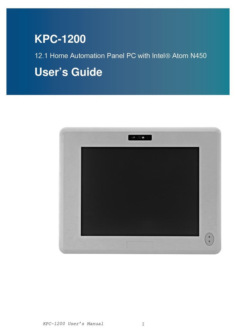
BIG TREE TECH Raspberry pad 5 V1.0 User manual

深圳市必趣科技有限公司
BIGTREETECH
1/ 17
BIGTREETECH
Raspberry pad 5
V1.0
Instruction Manual

深圳市必趣科技有限公司
BIGTREETECH
2/ 17
TABLE OF CONTENTS
TABLE OF CONTENTS ............................................................2
DOCUMENT CHANGE HISTORY ......................................................4
1. Introduction ..............................................................5
1.1 Features .............................................................5
1.2 Specification ........................................................5
1.3 Peripheral Port ......................................................6
1.3.1 Dimensions .....................................................6
1.3.2 Port diagram ...................................................6
1.3.3 Indicator lights ...............................................6
2. Port specification ........................................................7
2.1 CM4 installation .....................................................7
2.2 USB & CANBus mode of Type-C port .....................................7
2.3 Onboard CANBus .......................................................8
2.4 MCU Reset ............................................................8
2.5 40 pin GPIO ..........................................................9
3. System Installation ......................................................10
3.1 Preparations ........................................................10
3.1.1 OS image download .............................................10
3.1.2 Download and install Raspberry Pi Imager ......................10
3.2 LITE Version(Micro SD card) .........................................11
3.3 eMMC version ........................................................14
4. System Settings ..........................................................15
4.1 USB 2.0 Hub .........................................................15
4.2 DSI1 display ........................................................15
4.3 CSI1 Camera .........................................................15
4.4 RTC .................................................................15
4.5 CANBus ..............................................................16

深圳市必趣科技有限公司
BIGTREETECH
4/ 17
DOCUMENT CHANGE HISTORY
VERSION
CHANGES
RELEASE DATE
01.00
Initial release
2022/02/23
01.01
The latest bullseye version image (2022-01-28-
raspios-bullseye-armhf.zip) supports enabling
DSI/CSI/RTC on the same I2C at the same time
2022/03/17
01.02
Add the pin out description of 40 pin GPIO
2022/04/07
01.03
Added the description of the new version
Raspberry Pi Imager setting menu
2022/04/08

深圳市必趣科技有限公司
BIGTREETECH
5/ 17
1. Introduction
BIGTREETECH Raspberry pad 5 V1.0 is an Raspberry pi CM4 module expansion board
with IPS HD display developed by Shenzhen Bigtree Technology Co.,Ltd
1.1 Features
1. 800*480 IPS HD Captive display with wider viewing angle,Brightness &
display direction adjustable,Driven by DSI1 port on CM4 module.
2. HDMI0 port,Connection to external Display supported up to 2K resolution.
3. 15Pin 1.0mm CSI1 port
4. 3xUSB 2.0 port
5. Gigabit Ethernet port
6. USB & Ethernet port equipped with ESD protection.
7. Onboard RTC chip PCF8563 powered by CR1220 battery
8. 40Pin I/O pins identical to Raspberry pi
9. Multipurpose USB Type-C connection for flashing eMMC OS onto CM4 or CANbus
connection, and power supply
10. Type-C function selection by switch:eMMC OS flashing / CANBus
11. BTB(Board to Board) connection to CM4 reinforced with screw stud
12. Onboard mounting stud for fixture onto outer casing
13. Fully SMT produced.
1.2 Specification
1. Outer dimension:121*75.9mm
2. Mounting dimension:113*67.9mm
3. Display Area Dimension:108*64.8mm
4. Input voltage:Type-C 5±0.25V
5. Captive touch screen spec:IC-GT911 Structure:G+G

深圳市必趣科技有限公司
BIGTREETECH
6/ 17
1.3 Peripheral Port
1.3.1 Dimensions
1.3.2 Port diagram
*Warning: The voltage of the Type-C is ONLY 5V, Please don’t wire to the Type-C
of the HermitCrab Canbus(24/12V). Otherwise it will cause irreversible damage
to Pad5 & CM4.
1.3.3 Indicator lights
Equipped with 3 onboard indicator light for system diagnostics,RED led
indicating power source connected, Blue led indicating raspberry pi powered on,
Green led indicating OS is running.

深圳市必趣科技有限公司
BIGTREETECH
7/ 17
2. Port specification
2.1 CM4 installation
CM4 module Mounting orientation: “Made in UK” marking on the CM4 module
should face the USB-A port on the Pad 5。Four screws can be used to fix the CM4
module more securely on to the Pad5.
2.2 USB & CANBus mode of Type-C port
To ensure maximum expandability,the onboard Type-C port supports both USB
(EMMC flashing)and CANBus mode。Please refer to switch position of USB/CANBus
mode shown below in the picture.

深圳市必趣科技有限公司
BIGTREETECH
8/ 17
2.3 Onboard CANBus
When using CANBus Mode,set switch 4(CAN_CS highlighted in picture below)to
ON position(To the left),the onboard MCP2515 will use GPIO9(MISO)、 GPIO10
(MOSI)、 GPIO11(SCK)、 GPIO8(CS)、 GPIO25(INT)as SPI IO. If you wish to use
said IOs for other functions,Set the switch to OFF position (To the right) to
set the TypeC port to CANBus mode.
2.4 MCU Reset
The board utilizes the MCU to control the conversion of MIPI DSI signal to RGB
signal which controls the onboard screen. If any errors were to occur, please
reset the MCU by pressing the highlighted button in the picture below.

深圳市必趣科技有限公司
BIGTREETECH
9/ 17
2.5 40 pin GPIO
The 40 pin GPIO port pin sorting is exactly the same as the raspberry pi.

深圳市必趣科技有限公司
BIGTREETECH
10 / 17
3. System Installation
3.1 Preparations
3.1.1 OS image download
Download the OS image from raspberry pi official website
https://www.raspberrypi.com/software/operating-systems(you can also download Fluidd
or Mainsail OS image directly ,the installation procedure is slightly
different from standard RPi 3B or 4B, please refer to the procedure shown
below to enable ports(USB,DSI etc) for the Pad5.
3.1.2 Download and install Raspberry Pi Imager
Download and install the official Imaging flashing software from Raspberry pi
official website: https://www.raspberrypi.com/software/

深圳市必趣科技有限公司
BIGTREETECH
11 / 17
3.2 LITE Version(Micro SD card)
1. Insert the Micro SD cad in to your computer
2. Click “CHOOSE OS”
3. Select “Use custom”,and select the OS image downloaded in previous steps

深圳市必趣科技有限公司
BIGTREETECH
12 / 17
4. Click the setting icon in the lower right corner
5. “Enable SSH”and click“SAVE”, There are other features that can be set
in this menu. Please modify them according to your own needs. Details are
as follows:
Set hostname: raspberrypi.local //Custom hostname Default:raspberrypi.local
Enable SSH
Set username and password // Custom username and password,Default
username: pi password:raspberrypi
Configure wireless LAN // Custom the SSID and password of WLAN

深圳市必趣科技有限公司
BIGTREETECH
13 / 17
6. Select the correct SD card(The selected storage device (i.e. the SD card)
will be formatted and all data remaining on that storage device will be
wiped. Be careful to not select the wrong storage device to prevent losing
valuable data),Click “WRITE”
7. Wait patiently for the writing process to complete

深圳市必趣科技有限公司
BIGTREETECH
14 / 17
3.3 eMMC version
note: OS on the SD card will not run with eMMC version
1. Install rpiboot
Windows download and install:
http://github.com/raspberrypi/usbboot/raw/master/win32/rpiboot_setup.exe
Mac & Linux download and install:
https://github.com/raspberrypi/usbboot#building
2. Set switch 1(USBOTG)and switch 2(BOOT)to On position(to the left) to
enter BOOT mode. Double check that Type-C port is in USB mode,not CANBus
mode.
3. Connect the TypeC port to your computer USB port(To prevent insufficient
power supply from the Computer USB port causing error,please plug the
cable into a USB hub with independent power supply,or power the CM4 with
external 5v power supply through the 5V terminal on the 40pin IO),Run
sudo ./rpiboot(On Mac/Linux)or rpiboot.exe(on windows),The eMMC on CM4
will be recognized by the computer as a storage device(If rpiboot report
error,please unplug and reinsert the USB)。
4. The procedures to Writing image using Raspberry Pi Imager is identical to
LITE Version,SSH feature also needs to be enabled。
5. After successfully installed the OS,set the switch 1(USBOTG)、 2(BOOT)
back to Off position(to the right) to enter normal operating mode。

深圳市必趣科技有限公司
BIGTREETECH
15 / 17
4. System Settings
4.1 USB 2.0 Hub
Pad5 is equipped with a onboard USB 2.0 Hub. The USB interface is disabled to
save power by default on the CM4 . To enable it you need to add the following
to the config.txt file :
dtoverlay=dwc2,dr_mode=host
4.2 DSI1 display
The default display connection is HDMI,But the Pad5 integrated display
utilizes the DSI1 port. To install the driver for the DSI1, enter the below
command into the terminal:
sudo wget https://datasheets.raspberrypi.com/cmio/dt-blob-disp1-cam1.bin -O /boot/dt-blob.bin
Reboot the system after the driver is successfully downloaded,the Pad5 display
should now work correctly ,to switch back to using HDMI port, the downloaded
/boot/dt-blob.bin needs to be deleted.
4.3 CSI1 Camera
The DSI1 driver downloaded in step 4.2 also contains the driver for CSI1. If
you desire to download only the CSI1 driver, Find the desired driver in
https://datasheets.raspberrypi.com/licence.html download in to the boot folder
on CM4 and rename to dt-blob.bin,and follow the guide in the link below:
https://projects.raspberrypi.org/en/projects/getting-started-with-picamera/
4.4 RTC
The onboard RTC on the Pad 5 is PCF8563. For the RTC to work correctly , a
CR1220 button cell needs to be installed. The RTC and DSI/CSI is sharing the
same set of I2C, we can enable DSI/CSI/RTC on the same I2C at the same time
using the latest bullseye version of image (2022-01-28-raspios-bullseye-
armhf.zip), the lines below needs to be added in config.txt:
dtparam=i2c_vc=on
dtoverlay=i2c-rtc,pcf8563,i2c_csi_dsi
The system clock will sync with the RTC clock after the above procedure.

深圳市必趣科技有限公司
BIGTREETECH
16 / 17
4.5 CANBus
The Pad5 uses MCP2515 for SPI to CANBus conversion,set switch 4 (CAN_CS)to
ON position(to the left),And set CANBus switch to the right to set TypeC port
to CANBus mode.
Add the following configurations in config.txt to enable CANBus:
dtparam=spi=on
dtoverlay=mcp2515-can0,oscillator=12000000,interrupt=25,spimaxfrequency=1000000
After reboot,enter dmesg | grep -i '\(can\|spi\)' in terminal to check if
MCP2515 is operating,correct return should be as following:
[ 8.680446] CAN device driver interface
[ 8.697558] mcp251x spi0.0 can0: MCP2515 successfully initialized.
[ 9.482332] IPv6: ADDRCONF(NETDEV_CHANGE): can0: link becomes ready

深圳市必趣科技有限公司
BIGTREETECH
17 / 17
5. Precautions
1. Do NOT plug and unplug any connecters when powered on, Including flashing
EMMC
2. Please provide sufficient cooling to the CM4 module, The CM4 module needs
additional cooling aid when under heavy workload.
3. Please be careful when handling the Pad5 as the screen is very delicate.
If you inquire any other resources about this product, please go to
https://github.com/bigtreetech/ .Our technical support team will also be happy
to assist you with any further inquiries if you can’t find what you need on
our GitHub page.
And Please contact us if you encounter any other problem or have any
suggestions or complaints,we would happily assist you to resolve the issue,
Thank you for choosing BIGTREETECH product!
Table of contents

