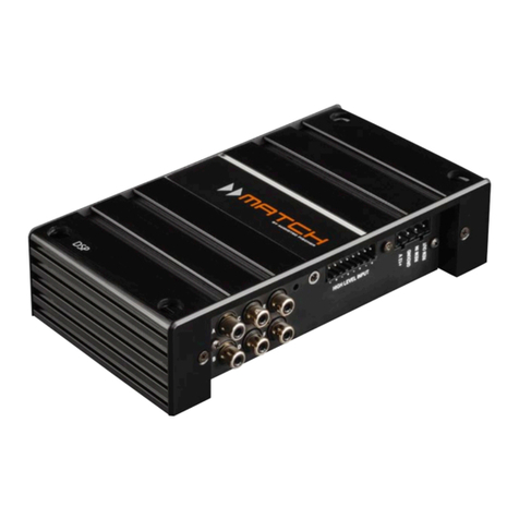
BIG CE234XL User manual

SIGNAI IDITOCNSSOIE
I,r.Fr'{,1.Frfl,4-l}.{,t Fu,t"ii,a.7, r:r.??&{:,ffi.T,::1fr'ffiAq i $",H,-&g.ET:.8.iffi j {r?"2'=
fu3'*7u,'j..'-:: =t;2!z?=;-* -:={..lzT7{3 'H:tlE7.i2Tu€,'lE:,,?:'=r7.-H"T T:A**X*%*A
*a:,+"8" 3"!i
2 13 I 4-WAY ELECTRONIC CROS SOVER
. .: . !-:-.J
:g- +
@ =-"ffi-"
g.-+
#ffi .,q EFHG' f,: aiffi Lte H .HA='',#,
Rev' 3.0-1112009

FseGessGem*G SGWwTG ffwmffiffisses
Thank you for selecting our products. , .
Please read this manual carefully to get the most out of your new unit.
1..
Caution : Do not let this unit touch the rain or get wet, to avoid the fire or electric shock.
FEAIURES
This is high exact electronic crossover, it has high-pass filter, can cut the low frequency disturb.
protect the speaker not to be broken. lnclude phase switch, separately high / low frequency gain
adjust. Easy for difference system's connection. lt is a stereo 2-way or 3-way crossover (or mono
4-way crossover) 24dBloctave crossover,can choose stereo or mono operation mode.
. XLR balanced ins and Outs
. 2wdy stereo/3 way Stereo ,4way mono Stereo Crossover
. Phase reverse switch on all outputs
. lndividual level controls on all band outputs
. 24dB per octave
. Linkwitz - Riley filters (the professional standard)
. Low frequency su mmed(subwoofer)output
o x10 range switch on both channels
. 4OHz high pass (low cut) filter both channels
. Stereo /mono status LEDs indicate the selected mode
G0l,lIE1,lIS:
IMP0BIAIII SATEIY l1{STRUGI|0ltls
FROifi PAl,IEt
REAR PAI'IET """""""" 2
-------- 3
IYPICAT SEI.UP (SIERE(I z.WAY)
IYPIGAT SEI.UP (SIEREO 3.WAY)
IYPIGAI SEI.UP (MOI.IO 4-WAY)
..------------" 5
sPEGtFtCAII0l'tS
c0ttl,tEGItoils

AffiA
CAUTION: TO REDUCE THE R SK OF ELECTR C SHOCK
DO NOT REMOVE COVER {OR BACK)
NO USER SERV CEABLE PARTS NS DE,
REFER SERVICING TO OUALIFIED SERVICE PERSONNEL
An equilateral triangle enclosing a lightening flash/arrowhead symbol is
intendedtoalerttheuser to the presence of un-insulated "dangerous
voltage" within the product's enclosure which may be of sufficient
magnitude to constitute a risk of electric shock.
An equilateral triangle enclosing an exclamation point is intended to alert
the user to the presence of important operating and service instructions in
the literature enclosed with this unit.
I M PORTANT SAF ETY I NSTRU CT"ION S
IM PORTANT SAFETY I NSIRUCTIONS
WARNING -When using electric products, basic precautions should always be followed, including the follbwing:
1. Read all the instructions before using the product.
2. Do notuse this product nearwater (e.9., near a bathtub, washbowl, kitchen sink, in a wet basement, near a swimming pool, etc.).
3. This product should be used only with a cart or stand that will keep it level and stable and prevent wobbling.
4. This product, in combination with headphones or speakers, may be capable of producing sound levels that could cause permanent
hearingloss. Donotoperateforalongperiodoftimeatahrghvolumeleveloratalevelthatisuncomfortable. lfyouexperienceany
hearing loss or ringing in the ears, you should consu t an audiologist.
5. The product should be located so that its locat on or position does not interfere with its proper ventilation
6. The product should be located away from heat sources such as radiators, heat vents, or other devices ( including amplifiers)that
produce heat.
7. The product should be connected to a power supply only of the type described in the operating instructions or as marked on the
product. Replace the fuse only with one of the specif ied type and size and with the correct rating,
B.The power-supply cord should: (1) be undamaged, (2) never share an outlet or extension cord with other devices so that the outlet's
orextensioncord'spowerratingisexceeded,or(3)beleftpluggedintotheoutletwhenleftunusedforalongperiodof time
9. Care should be taken so that objects do not fall into and liquids are not spilled through the enclosure's openings.
10. The product should be serviced by qualified service personnelwhen:
A. The power-supply cord or the plug has been damaged; or
B. 0bjects have fallen, or liquid has been spilled onto the product; or
C. The product has been exposed to rain; or
D. The product does not appear to operate normally or exhibits a marked change in performance; or
E. The product has been dropped, or the enclosure damaged.
11 . Do not attempt to service the product beyond that described in the user-maintenance instructions, All other servicing should be
referred to qualified service personnel.
IMPORTANT SAFETY INSTRUCTIONS
Thisproductmaybeequippedwithapolarizedlineplug(onebladewiderthantheother) Thisisasafetyfeature lfyouareunableto
inserttheplugintotheoutlet,contactanelectriciantoreplaceyourobsoleteoutlet Donotdefeatthesafetypurposeoftheplug.
(For use in the U.S.A.)
I M P 0 RTA N T: r H r wr RES r N T H r s MAr N s L EAD ARE c0 L0 R E D r N ACCo R DA N c E w r T H TH E F o LLow r N G c o D E.
BLUE: NEUTRAL / BROWN: LIVE ..'
As the colors of the wires in the mains lead of this apparatus may not correspond with the colored markings identifying the terminals in
your plug proceed as follows: The wire which is colored BLUE must be connected to the terminalwhich is marked with the leiter N or
colored BLACK. The wire which is colored BROWN must be connected to the terminal which is marked with the letter L or colored
RED. Under no circumstances must either of the above wires be connected to the ground terminal of a three-pin plug.
(For use in Europe)

STEREO 2.WAY MODE
ln 2-way stereo mode the controls are marked be,low the horizontal blue line. Channel l and channel 2 functions are identical in the
stereo mode. Front panel controls not describes in this section are not active in stereo 2-way operation.
Conlrols the INPUT level with +/- 12 dB of gain
Switch for selecting the 40Hz high pass filter An LED indicates the selection
Selects crossover poini betweert the LOW and HIGH ou-tpgJS
I'ndicates thatlhe LOW/HIGH crossoverfrequency range is 450 Hz to 9.6 kHz.
Controls the LOW frequency output level with a range of -o to +6d8.
Switch for reversing the polarity on the LOW outpgi. An LED indicates that the phase is inverted
Controls the HIGH frequency output with a range o!:r@ to +6d8. .. ,'
Switch for reversing the polarity on the HIGH output. An LED indicates that the phase is inverted
(1) & (7) rNPUT GArN
(13) & (20) LOW CUT
(2)& (B) LOW/MID
(14) &(21) x 10 LED
(4) & (10) LOW OUTPUT
(15) & (22) PHASE TNVERT
(6) & (12) HrGH OUTPUT
(17) & (24) PHASE TNVERT
(1e) STEREO
.Although the control is labeled
stereo 2-way operation
LED indicating stereo mode operation
as LOW/MlD, it operates as the crossoverfrequency control between low & high frequencies in
STEREO 3.WAY MODE
ln 3-way stereo mode the controls are marked below the horizontal blue Iine. Channel 1 and channel 2 functions are identical in the
stereo mode LEDs are disabled for controls which are non-functional in this mode.
Controls the INPUT level with +l- 12 dB of gain.
Switch for selecting the 40Hz high pass filterAn LED indicates the selection
Selects crossover point between the LOW and MID frequencies
lndicates that the LOW/HIGH crossover frequency range is 450 Hz to 9.6 kHz.
Select s crossover point between MID and HIGH frequencies
Controls the LOW frequency output level with a range of -o to +6dB.
Switch for reversing the polarity on the LOW output. An LED indicates that the phase is inverted
Controls the mid f requency output with a range of -o to +6dB.
Switch for reversing the polarity on the MID output. An LED indicates that the phase is inverted
Controls the HIGH frequency output with a range of -o to +6d8.
Switch for reversing the polarity on the HIGH output. An LED indicates that the phase is inverted
LED indicating stereo mode operation
MONO 4.WAY MODE
ln 4-way mono operation mode the controls are marked above the horizontal blue line. Front controls not described in this section
are not active jn mono 4-way mode. LEDs are disabled for controls which are non-functional in mono 4-way mode panel
(1) & (7) rNPUT GAtN
(13) & (20) LOW CUT
(2)& (B) LOW/MrD
(14) &(21 ) x 10 LED
(3) & (e) MrD/HtcH
(4) & (10) LOW OUTPUT
(15) & (22) PHASE TNVERT
(5)& (11) MtD OUTPUT
(16) & (23) PHASE TNVERT
(6) & (12) HtGH OUTPUT
(17) & (24) PHASE TNVERT
(19) STEREO
(1)
(1 3)
(2)
(14)
(3)
(e)
(4)
(1 5)
(5)
(16)
(11)
(23)
(12)
(24\
(1e)
INPUT GAIN
LOW CUT Controls the INPUT level with +l- 12 dB of gain.
Switch for selecting the 40Hz high pass filterAn LED indicates the selection
LOW/LOW-MlD Sele,cts crossover point between the LOW and LOW-MlD frequencies
x10LED lndicates that the LOW/LOW-MlD crossover frequency range is 45O Hz to 9.6 kHz
LOW-MID/HIGH-MlD Selects crossover point between LOW-MlD and HIGH-MlD frequencies
HIGH-MlD/HIGH Selects crossover point between HIGH-MlD and HIGH frequencies
LOW OUTPUT Controls the LOW frequency output level with a range of -@ to +6dB
PHASE INVERT Switch for reversing the polarity on the LOW output. An LED indicates that the phase is inverted
LOW-MlD OUTPUT Controls the LO_W MtD frequency output with a range of -o to +6d8.
PHASE INVERT Switch forur"?Eing the polarity on the MID output. An LED indicates that the phase is inverted
H IGH-MlD OUTPUT Controls the HIGH-MlD frequency output with a range of -@ to +6d8.
PHASE INVERT Switch for reversing the polarity on the MID output. An LED indicates that the phase is inverted
HIGH OUTPUT Controls the HIGH frequency output with a range of -o to +6d8.
PHASE INVERT Switch for reversing the polarity on the HIGH output. An LED indicates that the phase is inverted
STEREO LED indicating stereo mode operation
2

1 .AC CHORD
2. FUSE COMPARTMENT
3 - HIGH OUTPUT
4. HIGH/MID OUTPUT Ch2 :
5 - LOW OUTPUT Ch2
6 . CROSSOVER FREQUENCY X 1O SWITCH
7.CHzINPUT
8 . STEREO/MONO SWITCH
9.STEREO/MONO SWITCH
10. LF SUM SWITCH
11 , CH1 HIGH OUTPUT
12. CHl HIGH/MID OUTPUT
13. LOW OUTPUT Ch1
14 . CROSSOVER FREQUENCY X 1O SWITCH
rl
15. CH1 SIGNAL INPUT .
3

High Amplifier
High Speaker
Low Speaker
Mixing Consoie
@
oo
{

High Speaker
\11c1 Speaker
High Amplifier
l@l l@l L,,rs-eaker
lo ol lo ol
i#
5

t-
[rc,#r
Mid Amplifier
IEE
High Speaker
Mid Speaker
HLowspeaker
Sub Speaker
Mixing Console
Sub Amplifier
ia?
6

INPUT CONNECTORS
TYPE
IMPEDANCE
MAX INPUT LEVEL
CMRR
OUTPUT CONNECTORS
TYPE
IMPEDANCE
MAX OUTPUT LEVEL
PERFORMANCE
BANDWIDTH
FREQUENCY RESPONSE
SICNAL TO NOISE :
LOW OUTPUT
LOW-MID OUTPUT
MID OUTPUT
HIGH-MID OUTPUT
HIGH OUTPUT
DYNAMIC RANGE
THD+NOISE
INTERCHANNAL CROSSTALK
CROSSOVER FREQUENCIES
STEREO MODE LOW/HIGH
LOW/MID
MID/HIGH
MONO MODE LOW/LOW-MID
LOW-MID/HIGH-MID
HIGH-MID/HIGH
FILTER TYPE
FUNCTION SWITCH
FRONTPANEL LOWCUT
PHASE INVERT
REAR PANEL x10
MODE
LF SUM
INDICATORS
STEREO OPERATION
MONO OPERATION
LOW CUT
x10
PHASE INVERT
POWER SUPPLY d,r
OPERATING VOLTAGE
POWER CONSUMPTION
MAINS CONNECTION
PHYSICAL
DIMENSIONS (WxHxD)
NORMAL WEIGHT
SHIPPING WEIGHT
:XLR
: ELECTRONICALLY BALANCED/UNBALANCED, RF FILTERED
: BALANCED > SOKOhm, UNBALANCED > 25KOhm
: > +22dB:u TYPICAL, BALANCED OR UNBALANCED
: > 40dB, TYPICALLY > 55dB AT lKHz
:XLR
: IMPEDANCED BALANCED/UNBALANCED, RF FILTERED
: BALANCED 200Ohm, UNBALANCED 100Ohm
: > +21dBu BALANCED/UNBALANCED INTO 2KOhm OR GREATER
:20HzTO 20KHz , +0/-}.EdB
: < 3Hz TO > 90KHz , +0/-3dB -..,.
REF +4dBu ,22KHz MEASUREMENT BANDWIDTH
STEREO MODE
> 94dR . MONO MODE
l': :, > 94dB
':" > 94dB
> 93dB > 92dB
> 90dB > 88dB
: > 106dB, UNWEIGHTED, ANy OUTPUT
: < 0.004% AT +4dBu ,7KHz
: < 0.0470 AT +20dBu ,7KHz
: < -EOdB ,2}HzTO 20KHz
: -15H2 TO 960H2 OR 4S0Hz TO 9.6KHz (x10 SETTING)
: 45Hz TO 960H2 OR 450H2 TO 9.6KHz (x10 SETTING)
: 45AHz TO 9.6KHz
: 45Hz TO 960H2 OR 450H2 TO 9.6KHz (x10 SETTI\G,
: 150H2 TO 9.6KHz
: 450H2 TO 9.6KHz
: LINKWITZ- RILEY, L4dB/OCTAVE , STATE-\'.{RjL-{3LE
: ACTIVATES 40Hz BUTTERWORTH , 12dB /OCT_\\E r{IGH_P-{SS
FILTER, ONE SWITCH PER CH.I\\EL
: INVERTS THE PHASE AT THE OLTPLT ,
ONE SWITCH PER OUTPUT
: MULTIPLIES CROSSOVER FREQLT\CY R{\GE BY 10,
ONE SWITCH PER CHA\-\EL
: SELECTS STEREO/MONO -A\-D 2/3/4-wA\ OPERATION
: SELECTS NORMAL (STEREO) OR MONO-SUMMED LOW
FREQUENCY OPERATIO\
: GREEN LED
: YELLOW LED
: RED LED PER CHANNEL
: GREEN LED PER CHANNEL
: RED LED PER OUTPUT (3 PER CHANNEL)
: 1 10- L2Ol60Hz ot 20O-240150H2 VAC Selectable
: 7 WATTS
: IEC 320 RECEPTACLE
: 482x44.5x746 mm.
: 2.5 Kg.
: 3.0 Kg.
a

Balanced Mic XLR Mix Outputs
.o,
@2. Hot (+ve)
e. iolo (-ve)
.C.
@
1. Screen 2.Signal +
,j r.;
'.t,r
t--1. Screen
3. Signal -
3 pole jack
Balanced
2 pole jack
Unbalanced
Hot (+vs;
Cold (-ve)
Ground i
Screen
+ve lead to Tip
-ve lead to Ring
Sleeve
Signal
Ground /
Screen
+ve lead to Tip
T--ve lead and
-sleeve to Ground
t
I
Table of contents
Popular Signal Processor manuals by other brands

Microsemi
Microsemi IGLOO 2 Demo guide
Motorola
Motorola Freescale Semiconductor DSP56000 manual
Drawmer
Drawmer TwoPlusTwo Dynamics DSL424 Operator's manual
Kurzweil
Kurzweil Artis SE Musician's guide

Bass Habit
Bass Habit ELITE E28DSP user manual
Motorola
Motorola Freescale Semiconductor DSP56000 user manual
