BigDog Mower DIABLO User manual

123936 REV B
BIGDOG®MOWER CO. DIABLO®
General Service Manual
200 South Ridge Road
Hesston, Kansas
67062

The Engine Owner’s Manual provides information regarding the U.S. Environmental Protection Agency (EPA)
and the California Emission Control Regulation of emission systems, maintenance and warranty.
Keep Engine Owner’s Manual with your unit. Should the Engine Owner’s Manual become damaged or
illegible, replace immediately. Replacements may be ordered per the information found in the Product
Information section of the owner’s manual.
Federal law and California State law prohibit the following acts or the causing thereof:
1. The removal or rendering inoperative by any person other than for purposes of maintenance,
repair, replacement, of any device or element of design incorporated into any equipment for the
purposes of emissions control prior to or after its sales or delivery to the ultimate purchaser or
while it is in use, or
2. The use of the equipment after such device or element of design has been removed or rendered
inoperative by any person.
NOTICE OF REQUIREMENT OF SPARK ARRESTER MUFFLER
This equipment may create sparks that can start fires around dry vegetation. California Public Resources Code
Section 4442.6 provides that it is unlawful to use or operate an internal combustion engine on any forest-covered,
brush-covered, or grass-covered land unless the engine is equipped with a spark arrester maintained in effective
working order. A spark arrester is a device constructed of nonflammable materials specifically for the purpose of
removing and retaining carbon and other flammable particles over 0.0232 of an inch in size from the exhaust flow of
an internal combustion engine that uses hydrocarbon fuels or which is qualified and rated by the United States
Forest Service. Other states or federal areas may have similar laws. The Operator Should Contact Local Fire
Agencies For Laws or Regulations Relating to Fire Prevention Requirements. THIS EQUIPMENT DOES NOT HAVE
A SPARK ARRESTER AND YOU SHOULD CONTACT YOUR AUTHORIZED DEALER FOR THE PURCHASE OF
A SPARK ARRESTER.
Inspect spark arrester daily; replace every 500 hours or as needed.
WARNING
The engine exhaust from this product
contains chemicals known to the state
of California to cause cancer, birth
defects or other reproductive harm.
REV B 123936

123936 toc-1 REV B
Table of Contents
General Information . . . . . . . . . . . . . . . . . . . . . . . . . . . . . . . . . . . . . . . . . . . . . 1-1
Service Program . . . . . . . . . . . . . . . . . . . . . . . . . . . . . . . . . . . . . . . . . . . . . 1-1
Maintenance Introduction. . . . . . . . . . . . . . . . . . . . . . . . . . . . . . . . . . . . . 1-1
Warranty . . . . . . . . . . . . . . . . . . . . . . . . . . . . . . . . . . . . . . . . . . . . . . . . . . . 1-1
Safety. . . . . . . . . . . . . . . . . . . . . . . . . . . . . . . . . . . . . . . . . . . . . . . . . . . . . . . . . 2-1
Safe Servicing Practices . . . . . . . . . . . . . . . . . . . . . . . . . . . . . . . . . . . . . . 2-1
Pre-Operation Precautions . . . . . . . . . . . . . . . . . . . . . . . . . . . . . . . . . . . . 2-1
Operation Precautions. . . . . . . . . . . . . . . . . . . . . . . . . . . . . . . . . . . . . . . . 2-2
Operate Machine Safely . . . . . . . . . . . . . . . . . . . . . . . . . . . . . . . . . . . . . . 2-2
General Maintenance Precautions. . . . . . . . . . . . . . . . . . . . . . . . . . . . . . 2-3
Maintenance Precautions . . . . . . . . . . . . . . . . . . . . . . . . . . . . . . . . . . . . . 2-3
Torque . . . . . . . . . . . . . . . . . . . . . . . . . . . . . . . . . . . . . . . . . . . . . . . . . . . . . . . . 3-1
Standard Torques. . . . . . . . . . . . . . . . . . . . . . . . . . . . . . . . . . . . . . . . . . . . 3-1
Special Torques . . . . . . . . . . . . . . . . . . . . . . . . . . . . . . . . . . . . . . . . . . . . . 3-1
Power Unit Maintenance . . . . . . . . . . . . . . . . . . . . . . . . . . . . . . . . . . . . . . . . . 4-1
Steering Adjustments . . . . . . . . . . . . . . . . . . . . . . . . . . . . . . . . . . . . . . . . 4-1
Park Brake Adjustment . . . . . . . . . . . . . . . . . . . . . . . . . . . . . . . . . . . . . . . 4-5
Belts. . . . . . . . . . . . . . . . . . . . . . . . . . . . . . . . . . . . . . . . . . . . . . . . . . . . . . . 4-7
Hydraulic Pump Belt Adjustment. . . . . . . . . . . . . . . . . . . . . . . . . . . . . . . 4-7
Hydraulic System . . . . . . . . . . . . . . . . . . . . . . . . . . . . . . . . . . . . . . . . . . . . 4-8
Warner Clutch Re-gap Adjustment Procedures . . . . . . . . . . . . . . . . . . . 4-9
Tires . . . . . . . . . . . . . . . . . . . . . . . . . . . . . . . . . . . . . . . . . . . . . . . . . . . . . . 4-11
Caster Fork Tapered Bearing Replacement . . . . . . . . . . . . . . . . . . . . . 4-11
Engine Maintenance. . . . . . . . . . . . . . . . . . . . . . . . . . . . . . . . . . . . . . . . . . . . . 5-1
General Engine Maintenance . . . . . . . . . . . . . . . . . . . . . . . . . . . . . . . . . . 5-1
Engine Oil and Filter. . . . . . . . . . . . . . . . . . . . . . . . . . . . . . . . . . . . . . . . . . 5-1
Engine Air Filter . . . . . . . . . . . . . . . . . . . . . . . . . . . . . . . . . . . . . . . . . . . . . 5-1
Fuel Evaporation System Filter . . . . . . . . . . . . . . . . . . . . . . . . . . . . . . . . 5-3
Fuel & Evaporative System Line Routings . . . . . . . . . . . . . . . . . . . . . . . 5-3
Deck Adjustments . . . . . . . . . . . . . . . . . . . . . . . . . . . . . . . . . . . . . . . . . . . . . . 6-1
Deck Leveling . . . . . . . . . . . . . . . . . . . . . . . . . . . . . . . . . . . . . . . . . . . . . . . 6-1
Blades . . . . . . . . . . . . . . . . . . . . . . . . . . . . . . . . . . . . . . . . . . . . . . . . . . . . . 6-2
Belts. . . . . . . . . . . . . . . . . . . . . . . . . . . . . . . . . . . . . . . . . . . . . . . . . . . . . . . 6-3

REV B toc-2 123936
Deck Belt Adjustment. . . . . . . . . . . . . . . . . . . . . . . . . . . . . . . . . . . . . . . . . 6-3
Electrical . . . . . . . . . . . . . . . . . . . . . . . . . . . . . . . . . . . . . . . . . . . . . . . . . . . . . . 7-1
Electrical Schematic – Kawasaki . . . . . . . . . . . . . . . . . . . . . . . . . . . . . . . 7-1
Troubleshooting . . . . . . . . . . . . . . . . . . . . . . . . . . . . . . . . . . . . . . . . . . . . . . . . 9-1

123936 1-1 REV B
GENERAL INFORMATION
Service Program
This manual is part of a service package for the BigDog®
Diablo®mowers. Use of this manual in conjunction with other
BigDog®mower and component manuals will provide the
information necessary to service and maintain the BigDog®
Diablo® mower.
This General Service Manual is a service guide for use by
Service Technicians. It provides the necessary information
needed to perform normal maintenance requirements on
these units.
The Parts Manual provides a complete parts listing for the
unit. Use this manual when ordering parts.
The Operator's Manual provides fundamental operational
information and operational safety that is needed when
operating the mower.
The component manuals are furnished by the various
manufacturers to be used for the troubleshooting and
servicing of their components.
Maintenance Introduction
Regular maintenance is the best prevention for downtime
or premature failure. The following pages contain suggested
maintenance information and schedules which the operator/
mechanic should follow on a routine basis.
Remain alert for unusual noises, they could be signaling a
problem. Visually inspect the machine for any abnormal wear
or damage. A good time to detect potential problems is while
performing scheduled maintenance service. Correcting the
problem as quickly as possible is the best insurance.
Clear away heavy build-up of grease, oil and dirt, especially
in the engine compartment and under the seat platform
areas; minute dust particles are abrasive to close-tolerance
engine and hydraulic assemblies.
Daily inspect mower for grass clippings and wire and string
tangles. The underside of the mower deck will collect a build-
up of grass clippings and dirt, especially when grass is wet or
has high moisture content. This build-up will harden,
restricting blade and air movement and will probably show a
lesser quality of cut. Therefore it should be removed
routinely.
To do this it will be necessary to raise and block the deck,
using jack stands or blocks, in the full up position and scrape
the build-up from underneath.
Some repairs require the assistance of a trained service
mechanic and should not be attempted by unskilled
personnel. Consult your BigDog®Mowers service center
when assistance is needed.
Information included in this manual was current at the time
of printing, but subsequent production changes may cause
your machine to vary slightly in detail. BigDog®Mowers
reserves the right to redesign and change the machine as
deemed necessary, without notification. If a change has been
made to your machine which is not reflected in this service
manual contact the Customer Service Department at
BigDog®Mowers for additional information.
Warranty
Warranty repair must be performed by a BigDog®Mowers
Authorized Dealer before warranty credit can be allowed.

REV B 1-2 123936

123936 2-1 REV B
SAFETY
This safety alert symbol is used to call attention to a
message intended to provide a reasonable degree of
PERSONAL SAFETY for operators and other persons during
the normal operation and servicing of this equipment.
Safe Servicing Practices
Refer to the Safety Precautions section of this manual for
more service safety information.
Understand Correct Service
Be sure you understand a service procedure before
you work on the machine.
Unauthorized modifications to the machine may
impair the function and/or safety and affect machine
life.
If it is necessary to make checks with the engine
running, always use two people—with the operator at
the controls, able to see the person doing the
checking.
Pre-Operation Precautions
Fuel Handling
To avoid personal injury or property damage, use
extreme care in handling fuel. Fuel is extremely
flammable and the vapors are explosive.
Observe usual fuel handling precautions:
•Do not smoke while refueling. Extinguish all
cigarettes, cigars, pipes and other sources of
ignition.
• Do not remove fuel cap or fill tank with engine
running or while engine is hot. Clean up any fuel
spills.
•Allow engine to cool before storing machine
inside a building.
•Keep fuel away from open flame or spark and
store machine away from open flame or spark or
pilot light such as on a water heater or
appliances.
•Use extreme care when handling gasoline and
other fuels. They are extremely flammable and
vapors are explosive. A fire or explosion from fuel
can burn you and others and can damage
property.
•Refuel outdoors. Never refuel or drain the fuel
from the machine indoors.
•Never attempt to start engine when there is a
strong odor of gasoline or diesel fuel fumes
present. Locate and correct cause.
•Store fuel in an approved container and keep it
out of the reach of children. Never buy more than
a 30 day supply of fuel.
•Do not fill fuel containers inside a vehicle or on a
truck or trailer bed with interior carpets or plastic
truck bed liners. Always place fuel containers on
the ground away from your vehicle before filling.
•When practical, remove gas or diesel fuel
powered equipment from the truck or trailer and
refuel the equipment with its wheels on the
ground. If this is not possible, then refuel such
equipment on the truck or trailer using a portable
container and not a fuel dispenser nozzle. If a
fuel dispenser nozzle must be used, keep the
nozzle in contact with the rim of the fuel tank or
container opening at all times until fueling is
complete. Do not use a nozzle lock-open device.
•Never use gasoline or diesel fuel for cleaning
parts.
•Read and observe safety precautions elsewhere
in this manual.
Gasoline and diesel fuel is harmful or fatal if
swallowed.
•Long-term exposure to vapors can cause serious
injury and illness.
•Avoid prolonged breathing of vapors.
•Keep face away from nozzle and gas tank or fuel
container opening.
•Keep fuel away from eyes and skin.
•If fuel is spilled on clothing, change clothing
immediately.
Understand Machine Operation
To avoid personal injury or property damage, use
extreme care in handling fuel. Fuel is extremely
flammable and the vapors are explosive.
– denotes immediate hazards which WILL result in
severe personal injury or death.
– denotes a hazard or unsafe practice which
COULD result in severe personal injury or death.
DANGER
WARNING

REV B 2-2 123936
Observe usual fuel handling precautions:
•Do not smoke while refueling. Extinguish all
cigarettes, cigars, pipes and other sources of
ignition.
• Do not remove fuel cap or fill tank with engine
running or while engine is hot. Clean up any fuel
spills.
•Allow engine to cool before storing machine
inside a building.
•Keep fuel away from open flame or spark and
store machine away from open flame or spark or
pilot light such as on a water heater or
appliances.
•Use extreme care when handling gasoline and
other fuels. They are extremely flammable and
vapors are explosive. A fire or explosion from fuel
can burn you and others and can damage
property.
•Refuel outdoors. Never refuel or drain the fuel
from the machine indoors.
•Never attempt to start engine when there is a
strong odor of gasoline or diesel fuel fumes
present. Locate and correct cause.
•Store fuel in an approved container and keep it
out of the reach of children. Never buy more than
a 30 day supply of fuel.
•Do not fill fuel containers inside a vehicle or on a
truck or trailer bed with interior carpets or plastic
truck bed liners. Always place fuel containers on
the ground away from your vehicle before filling.
•When practical, remove gas or diesel fuel
powered equipment from the truck or trailer and
refuel the equipment with its wheels on the
ground. If this is not possible, then refuel such
equipment on the truck or trailer using a portable
container and not a fuel dispenser nozzle. If a
fuel dispenser nozzle must be used, keep the
nozzle in contact with the rim of the fuel tank or
container opening at all times until fueling is
complete. Do not use a nozzle lock-open device.
•Never use gasoline or diesel fuel for cleaning
parts.
•Read and observe safety precautions elsewhere
in this manual.
Gasoline and diesel fuel is harmful or fatal if
swallowed.
•Long-term exposure to vapors can cause serious
injury and illness.
•Avoid prolonged breathing of vapors.
•Keep face away from nozzle and gas tank or fuel
container opening.
•Keep fuel away from eyes and skin.
•If fuel is spilled on clothing, change clothing
immediately.
Wear Protective Clothing
Do not operate or service the equipment while wearing
sandals, tennis shoes, sneakers, shorts or any type of
loose fitting clothing. Long hair, loose clothing or
jewelry may get tangled in moving parts. Always wear
long pants, safety glasses, ear protection and safety
shoes when operating or servicing this machine.
Always wear adequate eye protection when servicing
the hydraulic system and battery, or when grinding
mower blades and removing accumulated debris.
Prolonged exposure to loud noise can cause
impairment or loss of hearing.
•Always wear adequate ear protection, such as
earplugs, when operating this equipment as
prolonged exposure to uncomfortable or loud
noises can cause impairment or loss of hearing.
•Do not wear radios or music headphones while
operating the machinery. Safe operation requires
your full attention.
Operation Precautions
Avoid Fire Hazards
Clean flammable material from machine. Prevent fires by
keeping engine compartment, top of deck, exhaust area,
battery, hydraulic lines, fuel line, fuel tank and operator’s
station clean of accumulated trash, grass clippings, and
other debris. Always clean up spilled fuel and oil.
Start Engine Safely
Avoid possible injury or death from machine runaway.
Do not start engine by shorting across starter
terminals.
Before you start the engine:
•Sit on the operator’s seat.
•Move control levers to the neutral/brake position.
Operate Machine Safely
Refer to the unit’s operator’s manual for complete
safety information on safe machine operation.
Always maintain a safe distance from people and pets
when mowing.
Always be aware of what is behind the machine before
backing up.
Never leave machine unattended with ignition key in
switch, especially with children present.
Follow daily and weekly checklists, making sure hoses
are tightly secured and bolts are tightened.
Always keep engine and machine clean, removing
accumulated dirt, trash and other material from
machine.
Never put hands or feet under any part of the machine
while it is running.

123936 2-3 REV B
Never attempt to start engine when there is a strong
odor of gasoline fumes present. Locate and correct
cause.
Keep all safety shields and covers in place, except for
servicing.
Do not touch hot parts of the machine.
General Maintenance Precautions
Repairs or maintenance requiring engine power should
be performed by trained maintenance personnel only.
Never run the engine in an enclosed area unless
exhaust is vented to the outside. Exhaust gases
contain carbon monoxide which is an odorless and
deadly poison.
Unless specifically required, DO NOT have the engine
running when servicing or making adjustments to the
mower.
•Park the mower on level ground
•Disengage the deck clutch.
•Place the steering control levers in the park brake
position.
•Lower the deck.
•Stop the engine.
•Remove the ignition key.
•Disconnect the negative battery cable.
•Wait for all movement to stop before adjusting,
cleaning or repairing.
•Repairs or maintenance requiring engine power
should be performed by trained maintenance
personnel only.
•To prevent carbon monoxide poisoning, operate
the engine in a well ventilated area only.
•Read and observe all safety warnings in this
manual.
Before working on or under the deck, make certain
engine cannot be accidentally started. Shut engine off,
remove ignition switch key and disconnect negative
battery cable for maximum safety.
Except when changing or checking belt, always keep
belt covers on mower deck for safety as well as
cleanliness.
Use a stick or similar instrument to clean under the
mower making sure that no part of the body, especially
arms and hands are under mower.
Keep your machine clean and remove any deposits of
trash and clippings, which can cause engine fires and
hydraulic overheating as well as excessive belt wear.
Clean up oil or fuel spillage.
Allow the mower, especially the engine, to cool in a well
ventilated area before storing inside a building or other
enclosure.
Always wear adequate eye protection when servicing
the hydraulic system and battery, or when grinding
mower blades and removing accumulated debris.
Never attempt to make any adjustments or repairs to
the mower drive system, mower deck or any
attachment while the engine is running or deck clutch
is engaged.
Exercise caution when releasing spring tension from
any of the belt idlers or when working with any of the
deck lift components.
Never work under the machine or attachment unless it
is safely supported with jack stands. Make certain
machine is secure when it is raised and placed on the
jack stands. The jack stands should not allow the
machine to move when the engine is running and the
drive wheels are rotating. Use only certified jack stands.
Use only appropriate jack stands, with a minimum
weight rating of 2000 pounds to block the unit up. Use
in pairs only. Follow the instructions supplied with the
vehicle stands.
Keep nuts and bolts tight, especially the blade
attachment bolts. Keep equipment in good working
condition.
Never tamper with safety devices. Check their proper
operation regularly.
Exercise caution when working under the deck as the
mower blades are extremely sharp. Wrap the blade(s)
or wear gloves and use extra caution when servicing
them.
Use original BigDog®Mower replacement parts or
parts that are equivalent in overall performance.
•The mower may not comply with the appropriate
safety standards if aftermarket parts,
accessories, or attachments are used.
Maintenance Precautions
Avoid Fire Hazards
Be prepared if an accident or fire should occur. Know
where the first aid kit and the fire extinguishers are
located and how to use them.
Provide adequate ventilation when charging batteries.
Do not smoke near battery.
Never check fuel level with an open flame.
Never use an open flame to look for leaks anywhere on
the equipment.
Never use an open flame as light anywhere on or
around the equipment.
When preparing engine for storage, remember that fuel
stabilizer is volatile and therefore dangerous. Seal and
tape openings after adding the inhibitor. Keep
container tightly closed when not in use.
Inspect electrical wiring for worn or frayed insulation.
Install new wiring if wires are damaged.

REV B 2-4 123936
Prepare for Emergencies
Be prepared if a fire starts.
Keep a first aid kit and fire extinguishers available.
Keep emergency numbers for doctor, ambulance
service, hospital, and fire department near the
telephone.
Prevent Battery Explosions
Battery posts, terminals, and related accessories
contain lead and lead compounds, chemicals known to
the State of California to cause cancer and
reproductive harm. Wash hands after handling.
Charge batteries in an open well-ventilated area, away
from sparks and flames. Unplug charger before
connecting or disconnecting from battery. Wear
protective clothing and use insulated tools.
Avoid skin and clothing contact with battery acid.
•Always wear eye protection when checking the
battery, acid can cause serious injury to skin and
eyes. If contact occurs, flush area with clean
water and call physician immediately. Acid will
also damage clothing.
•Do not drink the battery electrolyte.
•Do not allow open flame near the battery when
charging.
•Hydrogen gas forms inside the battery. This gas
is both toxic and flammable and may cause an
explosion if exposed to flame. Always disconnect
the negative (black) battery cable(s) before
disconnecting the positive (red) cable(s). Always
connect the positive (red) battery cable(s) before
connecting the negative (black) cable(s).
•Do not overfill battery.
•Electrolyte may overflow and damage paint,
wiring or structure. When cleaning the battery,
use soap and water. Be careful not to get soap
and water into the battery. Clean the battery
terminals with a solution of four parts water and
one part baking soda when they become
corroded.
Shorts caused by battery terminals or metal tools
touching metal mower components can cause sparks.
Sparks can cause a battery gas explosion which will
result in personal injury.
•Prevent the battery terminals from touching any
metal mower parts when removing or installing
the battery.
•Do not allow metal tools to short between the
battery terminals and metal mower parts.
Incorrect battery cable routing could cause damage to
the mower and battery cables. This can cause sparks
which can cause a battery gas explosion which will
result in personal injury. Always disconnect the
negative (black) battery cable(s) before disconnecting
the positive (red) cable(s). Always connect the positive
(red) battery cable(s) before connecting the negative
(black) cable(s).
Avoid Acid Burns
Sulfuric acid in battery electrolyte is poisonous. It is
strong enough to burn skin, eat holes in clothing and
cause blindness if splashed in eyes.
Avoid the hazard by:
•Filling batteries in a well-ventilated area.
•Wearing eye protection and rubber gloves.
•Avoiding breathing fumes when electrolyte is
added.
•Avoiding spilling or dripped electrolyte.
If you spill acid on yourself:
•Flush your skin with water.
•Apply baking soda or lime to help neutralize the
acid.
•Flush your eyes with water for 10-15 minutes. Get
medical attention immediately.
If acid is swallowed:
•Drink large amounts of water or milk.
•Then drink milk of magnesia, beaten eggs or
vegetable oil.
•Get medical attention immediately.

123936 3-1 REV B
TORQUE
Standard Torques
The following chart lists the standard torque values for the threaded fasteners found in this manual. Torque all cap screws, nuts
and set screws to these values unless a different torque is shown in the Special Torques section.
Special Torques
NOTE:
1. Lug nuts only – It is recommended that these be
checked after the first 2 hours of operation and every
50 hours and following removal for repair or replace-
ment.
2. Engine torque values – Refer to the respective engine
owner’s manual.
3. If clutch mounting bolt is loosened or removed, do not
re-use. Replace with a new bolt. Use only hand tools to
install this fastener.
Size ft-lbs N•m Size ft-lbs N•m
#10 32.4 IN.-LBS. 3.6 M3 12 IN.-LBS. 1.3
.250 98.4 IN.-LBS. 11.1 M4 26.4 IN.-LBS. 3
.312 204 IN.-LBS. 23 M5 54 IN.-LBS. 6.1
.375 30 40 M6 92.4 IN.-LBS. 10.4
.438 48 65 M8 222 IN.-LBS. 25
.500 73 99 M10 37 50
.562 105 143 M12 64 87
.625 145 200 M14 103 140
.750 260 350 M16 160 215
.875 420 565 M20 320 435
Description ft-lbs N•m
Wheel (lug) nuts 170 95
Blade spindle bolt top 70 95
Blade spindle bolt bottom 118 160
Electric clutch mounting bolt 347 63
Front wheel axle bolt 100 136
Wheel motor hub nut 230 312
Engine torques 2N/A N/A
Particular attention must be given to tightening the
drive wheel lug nuts and blade spindle bolts. Failure
to correctly torque these items may result in the loss
of a wheel or blade, which can cause serious dam-
age or personal injury.
WARNING

REV B 3-2 123936

123936 4-1 REV B
POWER UNIT MAINTENANCE
Steering Adjustments
Steering Control Lever Neutral Adjustment
The mower’s steering has been factory adjusted to
eliminate creeping when the steering control levers are in the
neutral position. However, should the mower begin to creep,
the steering control lever linkage can be adjusted.
Before considering any adjustment, check the tire air
pressure. Unequal tire pressure will cause the mower to drift
to one side. Refer to tire pressure information in the Tires
section for detailed information.
NOTE: Proper park brake adjustment must be completed
before the steering control lever neutral adjustment can be
done. Refer to the Park Brake Adjustment section for detailed
information.
Fine adjustment to the unit’s steering is made with the
transmission’s control rod.
Neutral is properly adjusted when the steering control
levers are in the park brake position and the transmissions
do not “whine”.
If the transmissions “whine”, the steering control linkage
may be adjusted as follows:
1. Raise the rear of the mower and block with certified
jack stands. The rear wheels need to be able to rotate
freely and clear of all obstructions.
2. Chock the front tires.
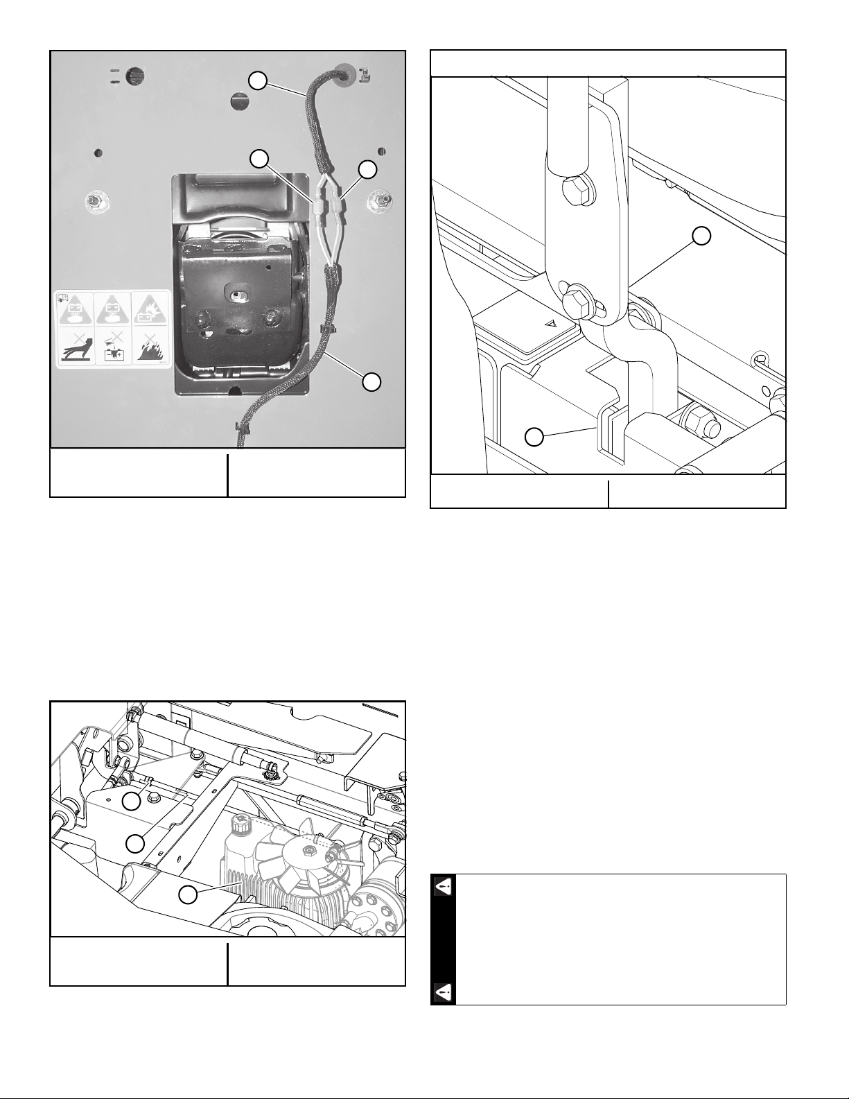
3. Raise the seat platform and disconnect the mower
harness from the seat switch. Bypass the seat switch
by connecting the two mower harness female spades
together. Figure 4-1 & Figure 4-2
Never work under the machine or attachment
unless it is safely supported with jack stands.
•Make certain machine is secure when it is
raised and placed on the jack stands.
• Use only certified jack stands. Use only
appropriate jack stands, with a minimum
weight rating of 2000 pounds (907 kg) to
block the unit up.
•Use in pairs only.
•Follow the instructions supplied with the
jack stands.
•The jack stands should not allow the
machine to move when the engine is running
and the drive wheels are rotating.
•Do not allow the wheels to come in contact
with the floor or any object that would permit
the unit to propel itself.
•To prevent injury stay clear and exercise
caution when rotating the wheels.
Keep hands, hair, clothing, etc., clear of the cooling
fans on top of the transmissions. Exercise extreme
caution.
Untrained maintenance personnel should never
attempt to make any adjustments or repairs to the
mower’s drive system while the engine is running.
The following procedures should be performed by
trained maintenance personnel only.
WARNING
WARNING
WARNING
A. Female spades
B. Seat switch
C. Mower harness
Figure 4-1
C
A
B
REV B 4-2 123936
4. Start the engine.
5. Position the steering control lever in the neutral
position and observe which way the wheels are
rotating. Figure 4-3
6. If wheel(s) are rotating forward, loosen the jam nuts on
the pump linkage rods and rotate the rod to shorten
the steering control linkage until the wheel(s) come to
a stop. Figure 4-4
7. Repeat for the opposite side if necessary.
8. If wheel(s) are rotating in reverse, then loosen the jam
nuts on the pump linkage rods and rotate the rod to
lengthen the steering control linkage until the wheel(s)
come to a stop. Figure 4-4
Repeat for the opposite side if necessary.
9. When both wheels remain stopped, tighten the jam
nuts to lock the turnbuckle in place.
10. Test again by moving the steering control levers
forward and backward before returning them to the
neutral position. If the tires do not rotate, the unit is
ready for operation.
11. After adjusting for neutral it may be necessary to re-
adjust the control lever stop and/or damper.
12. IMPORTANT: With the engine off, disconnect the two
female spade connectors from each other (from step
#3) and reconnect them to the seat switch. This must
be completed so that the safety circuit is functioning
properly. Figure 4-2
A. Female spades
B. Seat switch harness
C. Mower harness
Figure 4-2
A. Jam nut
B. Pump linkage rod
C. Pump
Figure 4-4
C
A
B
A
C
B
A
Steering control lever in neutral position
A. Park brake slot B. Steering control lever
Figure 4-3
Do not operate the mower without plugging the
mower’s wiring harness into the seat switch. This
switch is an important part of the safety start
interlock system. Serious injury can result if the seat
switch is not plugged into the mower’s wiring
harness.
B
A
WARNING

123936 4-3 REV B
13. Check to make sure all tools or obstructions are
removed from under the mower.
14. Raise the rear of the mower and remove the jack
stands. Lower the mower.
15. Remove the front wheel chocks.
16. Lower and secure the seat platform.
Control Lever Stops
The steering control lever stops (see Figure 4-5 &
Figure 4-6) are designed to do two things: first, and most
important, they must keep the pumps from bottoming out
internally. Secondly, the stops may be adjusted to help drive
straight when the steering control levers are pushed forward
against the stops.
To keep the pumps from bottoming out internally use
the following procedure:
NOTE: This adjustment normally is only required if the
hydraulic pump(s) have been replaced.
1. To make the first adjustment the mower engine must
not be running.
2. Check to make sure the steering control levers are
against the stops before the pumps are bottomed out
internally.
To do this, gently and slowly move the steering control
levers forward and feel if there is some resistance on the
pump lever before the control lever hits the stops.
NOTE: Check one side at a time.
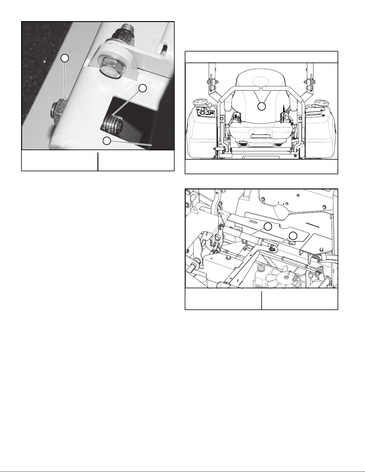
3. If the pump arm is stopping the forward motion of the
control arm, adjust the stop (set screw) inward to stop
the steering control levers slightly before the pump
bottoms out. After applying a threadlocker (e.g.,
Loctite 290), turn the stop screw inward until contact
is made with the inside of the steering cover, then turn
the stop screw an additional 1/4–1/2 turn. Figure 4-5
4. Do this for each side, then after the adjustment, fill the
sockets of the set screws with a tamper-proof sealant.
To adjust the stops for driving straight when steering
control levers are against the stops during operation:
1. Determine which drive tire is rotating too fast when
both steering control levers are against the stops in
the control panel. Figure 4-6
2. Stop the engine. Loosen the lock nut on the side which
is rotating too fast and turn the stop (set screw)
inward to stop the steering control lever sooner.
Figure 4-6
3. Tighten the lock nut on the stop and test again.
4. Repeat this procedure until both drive wheels rotate at
the same speed and the unit drives straight.
NOTE: Because this is a hydrostatic drive, variables such
as temperature of oil, efficiency of pumps and motors, tire
pressure, etc., may require the operator to make minor
steering adjustments with the control arms rather than rely
on just the stops to drive straight.
Steering Damper
The steering dampers are spring loaded to return the
control levers to the neutral position from the reverse
position. This gives the operator a sense of neutral during
operation.
To set the steering dampers in the correct operating
position, follow these steps:
1. Shut the engine off, place steering control levers in the
park brake position, disengage deck clutch, remove
ignition switch key and disconnect negative battery
cable before doing any adjustments.
2. Place the steering control lever in the neutral position.
Figure 4-7
Never operate the mower with a non-functioning
seat switch. Always reconnect the seat switch to the
mower harness.
Pump damage will occur if these stops are set
incorrectly.
WARNING
WARNING
A. Stop screw B. Steering damper
Figure 4-5
A
B
REV B 4-4 123936
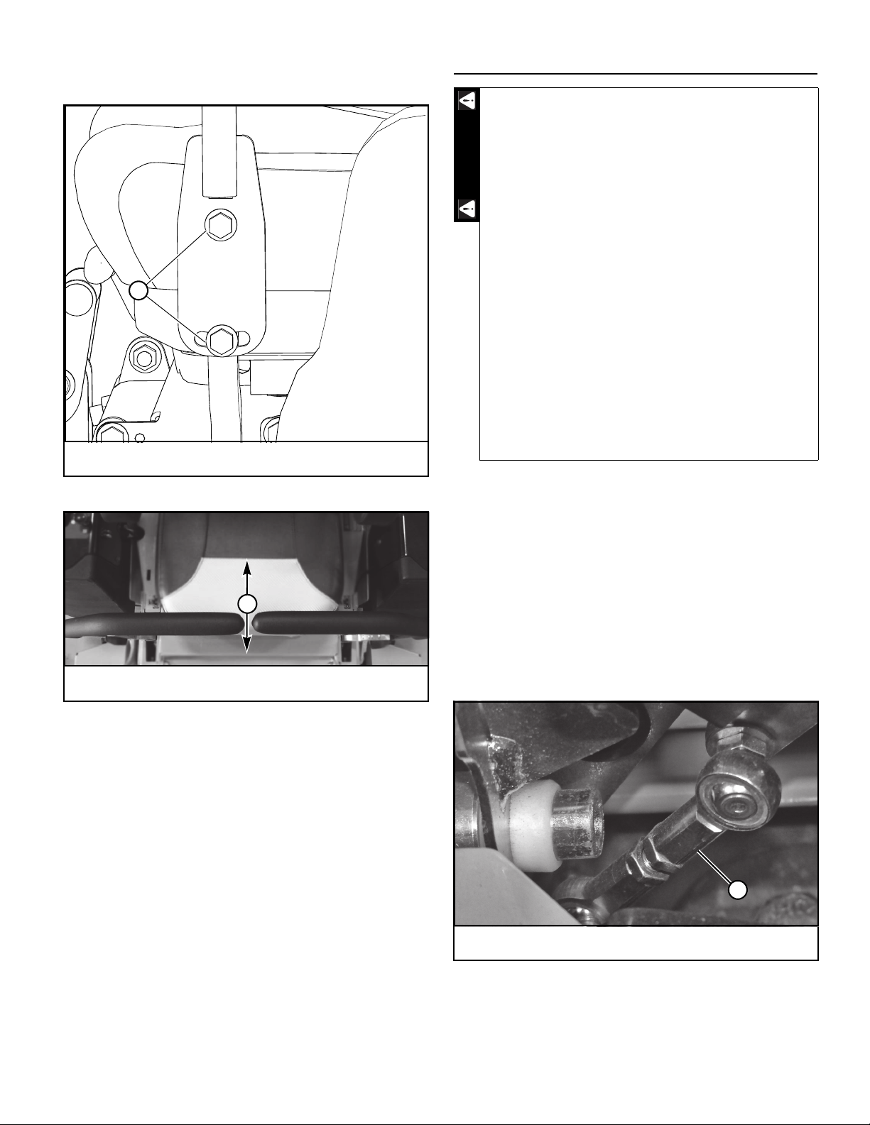
3. Loosen the nut on the steering damper rear ball stud
enough to allow the stud to move freely within the slot.
Figure 4-8
4. Pull the damper rod end toward the back of the slot,
past the point that the internal spring is engaged.
Figure 4-8
5. Release the rod end and allow the internal spring to
bring the rod end and ball stud back to the neutral
position.
6. Tighten the nut on the steering damper’s rear ball stud
to secure the final position.
NOTE: The damper must not bottom out when the pump
lever is fully stroked in either direction.
7. Reconnect the negative battery cable.
8. Lower and secure the seat platform.
9. To check, move the steering control lever to the
reverse position and release. The steering control lever
should return to the neutral position. If not, repeat
steps 1 through 6.
Steering Control Lever Adjustment
The steering control levers can be adjusted for operator
comfort.
1. Loosen the cap screws that attach the upper control
lever to the lower lever, then pivot the upper control
lever to fit the operator’s personal preference.
Figure 4-9
A. Jam nut
B. Stop (set screw)
C. Steering control lever
Figure 4-6
A
B
C
Shown with steering control levers in neutral position
A. Steering control lever
Figure 4-7
A. Steering damper spring
housing
B. Rear ball stud
Figure 4-8
A
A
B
123936 4-5 REV B
2. Adjust the steering control levers so that they align
with each other when in the neutral position.
Figure 4-10
Park Brake Adjustment
1. Shut engine off, place steering control levers in the
park brake position, disengage deck clutch, remove
ignition switch key and disconnect negative battery
cable before doing any adjustments.
2. Raise the rear of the mower and block with certified
jack stands. The rear wheels need to be able to rotate
freely and clear of all obstructions.
3. Chock the front tires.
4. Position the steering control levers in the neutral
position.
NOTE: The front brake link is not to be adjusted.
Figure 4-11
5. Open the hydraulic pump’s bypass (tow) valve, on the
side that is being adjusted, by turning the bypass valve
to open. Figure 4-12
A. Cap screws
Figure 4-9
A. Align steering handles to within ± .125” (3.175mm)
Figure 4-10
A
A
Never work under the machine or attachment
unless it is safely supported with jack stands.
•Make certain machine is secure when it is
raised and placed on the jack stands.
• Use only certified jack stands. Use only
appropriate jack stands, with a minimum
weight rating of 2000 pounds (907 kg) to
block the unit up.
•Use in pairs only.
•Follow the instructions supplied with the
jack stands.
•The jack stands should not allow the
machine to move when the engine is running
and the drive wheels are rotating.
•Do not allow the wheels to come in contact
with the floor or any object that would permit
the unit to propel itself.
•To prevent injury stay clear and exercise
caution when rotating the wheels.
A. Brake link
Figure 4-11
WARNING
A

REV B 4-6 123936
6. Try to rotate the tire by hand. The tire should rotate.
Remember hydraulic oil resistance will prevent the tire
from rotating freely even with the bypass valves open.
There should be no resistance from the brakes at this
point.
7. Move the steering control lever to where it is just
inside (1/4") the park brake slot. Figure 4-13
Mowers prior to serial number 18124866
A. Bypass (tow) valve lever in open
position
A. Bypass (tow) valve lever in drive
position
A. Bypass (tow) valve lever in open
position
Mowers beginning with serial number 18124866
A. Bypass (tow) valve lever in open
position
A. Bypass (tow) valve lever in drive
position
A. Bypass (tow) valve lever in open
position
Figure 4-12
A
A
A
A
A
A
123936 4-7 REV B
NOTE: When the steering control lever is against the
outside edge of the slot, the brakes should not be
engaged.
8. Rotate the tire. If the brake is adjusted properly the tire
will still rotate but friction will start to become
noticeable here. However, if no brake resistance is
noticed, the brake needs adjusted as follows:
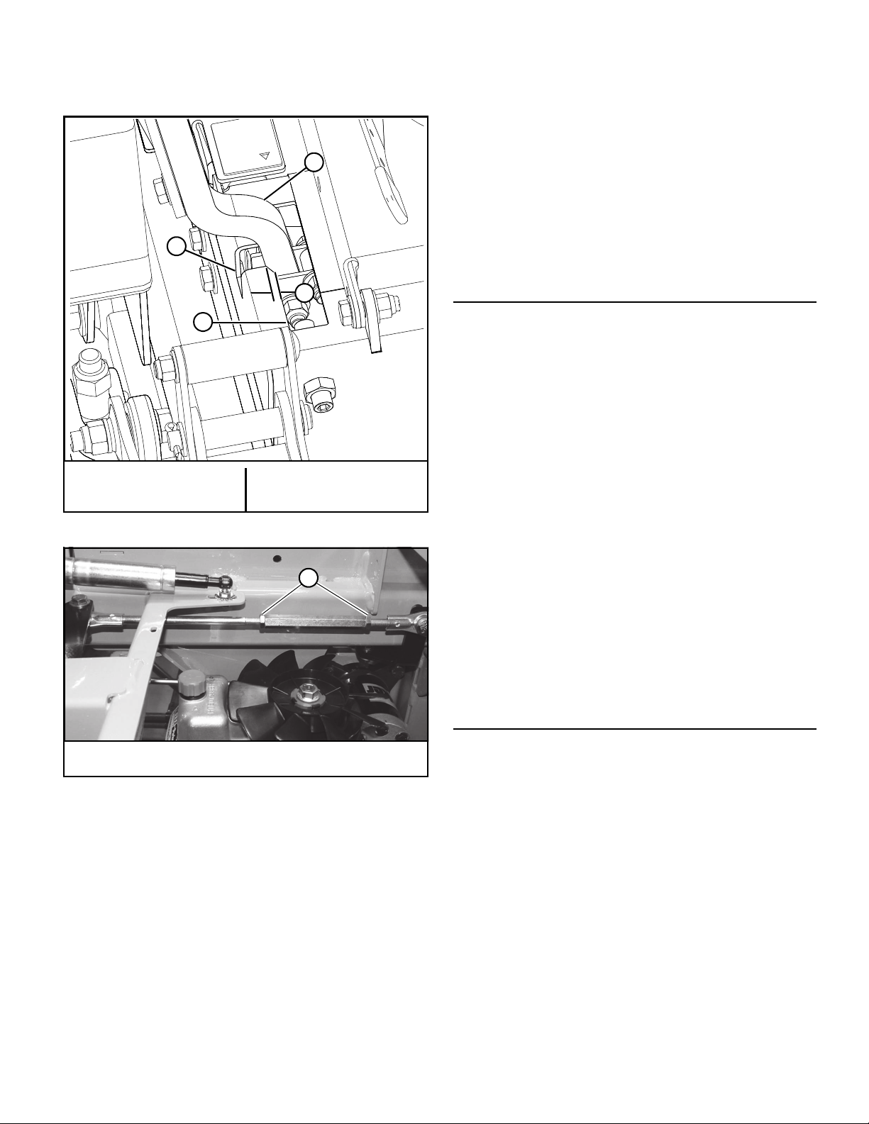
a. Loosen the brake linkage jam nuts. (Figure 4-14)
Rotate the tire and at the same time rotate the
turnbuckle to shorten the length of the brake linkage
to increase the brake pressure. When you feel the
brake begin to engage, stop adjusting the turnbuckle.
Re-tighten the jam nuts on the turnbuckle.
b. Place the control lever in the park brake slot. The tire
should not rotate when the control lever is in the park
brake position. Figure 4-13
c. Place the control lever in the neutral position. The tire
should rotate freely.
9. Close the hydraulic pump’s bypass valve. Figure 4-12
Repeat steps 4 through 9 for the other side.
10. Check to make sure all tools or obstructions are
removed from under the mower.
11. Remove the chocks from the front tires.
12. Raise the rear of the mower and remove the jack
stands. Lower the mower.
13. Reconnect the negative battery cable.
14. Lower and secure the seat platform.
Belts
Inspect belts frequently for wear and serviceability.
Replace a belt that shows signs of:
•severe cuts
•tears
•separation
•weather checking
•cracking
•burns caused by slipping.
Slight raveling of belt covering does not indicate failure,
trim ravelings with a sharp knife.
Inspect the belt pulley grooves and flanges for wear. A new
belt, or one in good condition, should never run against the
bottom of the groove. Replace the pulley when this is the
case, otherwise, the belt will lose power and slip excessively.
Never pry a belt to get it on a pulley as this will cut or
damage the fibers of the belt covering.
Keep oil and grease away from belts, and never use belt
dressings. Any of these will destroy the belt composition in a
very short time.
Hydraulic Pump Belt Adjustment
The transmission drive belt tension remains constant by
means of a tension idler and spring. The spring tension
should be such that the belt does not slip under normal
operating load conditions, assuming the belt is not
excessively worn or damaged. As the belt stretches and
wears in, adjustment may become necessary.
The proper belt tension is achieved when the tension
spring is stretched to a dimension of 7.5"–8.5" (191–216mm)
when measured from the inside of the hook to the inside of
the other hook. Figure 4-15
To increase belt tension, remove the spring hook from the
idler spring mount. Unbolt the idler spring mount from the
mower frame and move it to a set of holes in the frame that
allow for the spring to be extended to the proper extension.
Attach the mount and then re-attach the spring hook to it.
Figure 4-15
IMPORTANT: Do not over tension the spring to
compensate for a badly worn belt or pulley.
A. Steering control lever
B. Park brake slot
C. Outside edge
D. 1/4"
Figure 4-13
A. Jam nut
Figure 4-14
C
B
D
A
A
REV B 4-8 123936
Inspect the belt every 100 hours and replace as needed.
Replace the belt every 400 hours or every two (2) years
whichever comes first.
Hydraulic System
IMPORTANT: Never use hydraulic or automatic
transmission fluid in this system; use only specified oil.
Remember, dirt is the primary enemy of any hydraulic
system. Check oil level in hydraulic system after every 50
hours of operation or weekly, whichever occurs first. Check
more often if system appears to be leaking or otherwise
malfunctioning.
When checking the hydraulic system’s oil level:
1. Always check oil level with the mower on level ground.
2. Always check oil level when the oil is cold (mower has
not run for at least 1.5 hours).
3. Always check oil level with the dipstick installed and
tightened.
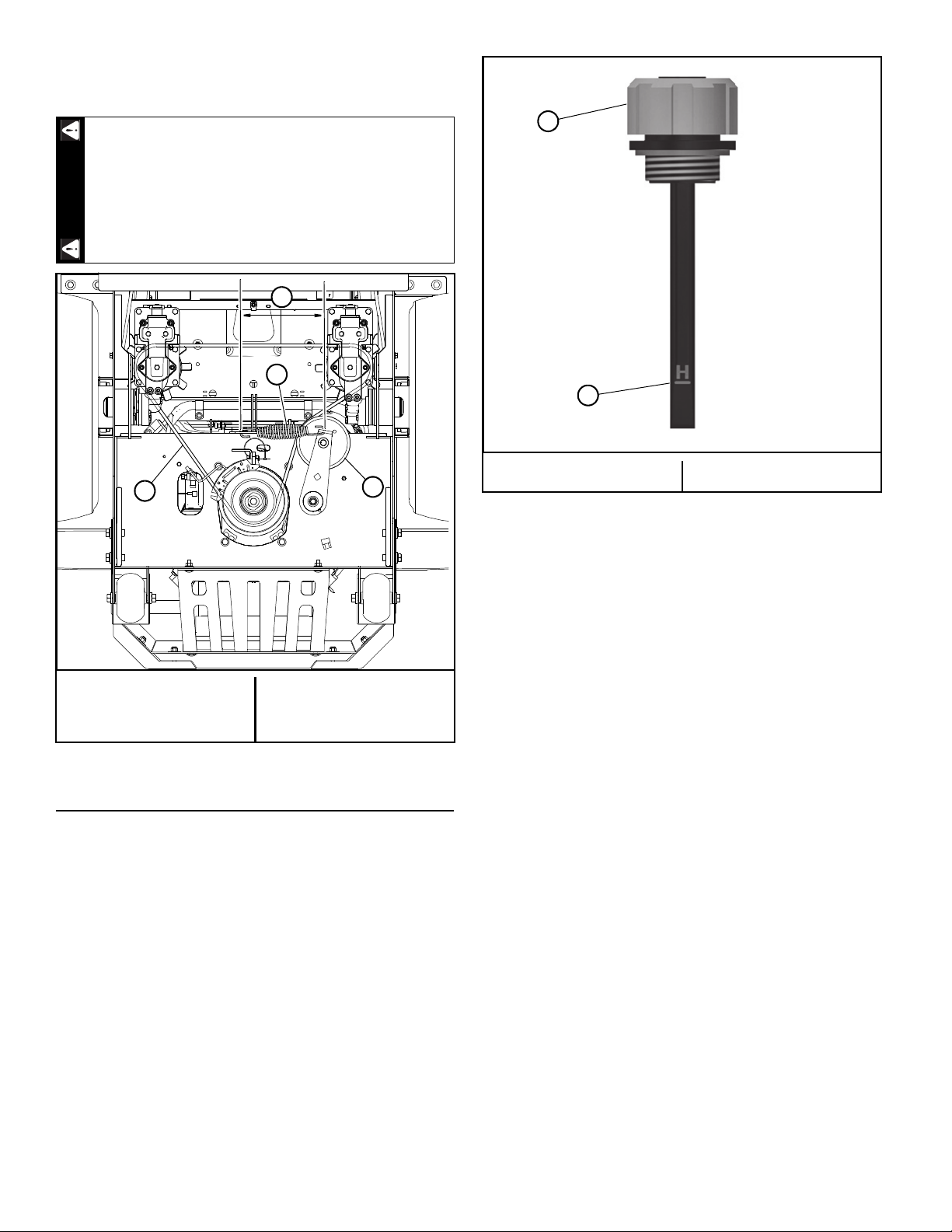
IMPORTANT: Full level when oil is cold is anywhere on
the dipstick, up to the “H” line. Oil must not be above
the "H" (High mark). Figure 4-16
Change hydraulic system filter element and oil after first
750 hours of mower operation, then replace filter and oil in
reservoir every 500 hours thereafter.
The following is a list of the oils that are approved for use
in the BigDog®Diablo®hydraulic system.
A. Parker HT-1000 (replace after every 750 hours)
B. Castrol Edge 5W-50
C. Shell Rotella T6 5W-40
D. Lucas – Magnum High TBN CI-4 15W40
E. Amsoil AW ISO 68
IMPORTANT: Use only the approved oils listed above. Use
of any unapproved oils will void your warranty.
The BigDog®Diablo®system filter is located at the bottom
of the integrated transmission with access to it from the
front. (Figure 4-17) Use a BigDog®approved filter element
only. When changing the filter use a 3/4” hex wrench. The
threads are right hand.
If the transmission belt fails, loss of control will
occur especially when operating on a slope. If you
lose steering control while operating the machine,
place the steering control levers in the park brake
position immediately. Inspect the machine and
involve your dealer to resolve the problem.
A. Hydraulic pump belt
B. Tension idler
C. Spring
D. 7.5"–8.5"
(191–216mm)
Figure 4-15
WARNING
AB
C
D
A. Dipstick B. "H" mark
Figure 4-16
A
B
Table of contents
Other BigDog Mower Lawn Mower manuals


Popular Lawn Mower manuals by other brands


Craftsman
Craftsman 917.371032 owner's manual

Husqvarna
Husqvarna Z3815BIA, Z3815BIA, Z4217BIA, Operator's manual

GreenWorks Commercial
GreenWorks Commercial 82SP25M Operator's manual

SNOWJOE
SNOWJOE SunJoe MJ24C-14-XR Operator's manual

Stiga
Stiga MJ 66 Quick guide for use

Robomow
Robomow RS 630 2015 Original operating instructions


