BigDog Mower STOUT MP User manual

121366 REV E
BIGDOG®MOWER CO. STOUT®MP
General Service Manual
200 South Ridge Road
Hesston, Kansas
67062

The Engine Owner’s Manual provides information regarding the U.S. Environmental Protection Agency
(EPA) and the California Emission Control Regulation of emission systems, maintenance and warranty.
Keep Engine Owner’s Manual with your unit. Should the Engine Owner’s Manual become damaged or illegi-
ble, replace immediately. Replacements may be ordered per the information found in the Product Informa-
tion section of the owner’s manual.
Federal law and California State law prohibit the following acts or the causing thereof:
1. The removal or rendering inoperative by any person other than for purposes of maintenance,
repair, replacement, of any device or element of design incorporated into any equipment for
the purposes of emissions control prior to or after its sales or delivery to the ultimate
purchaser or while it is in use, or
2. The use of the equipment after such device or element of design has been removed or
rendered inoperative by any person.
NOTICE OF REQUIREMENT OF SPARK ARRESTER MUFFLER
This equipment may create sparks that can start fires around dry vegetation. California Public Resources Code
Section 4442.6 provides that it is unlawful to use or operate an internal combustion engine on any forest-covered,
brush-covered, or grass-covered land unless the engine is equipped with a spark arrester maintained in effective
working order. A spark arrester is a device constructed of nonflammable materials specifically for the purpose of
removing and retaining carbon and other flammable particles over 0.0232 of an inch in size from the exhaust flow of
an internal combustion engine that uses hydrocarbon fuels or which is qualified and rated by the United States
Forest Service. Other states or federal areas may have similar laws. The Operator Should Contact Local Fire
Agencies For Laws or Regulations Relating to Fire Prevention Requirements. THIS EQUIPMENT DOES NOT HAVE
A SPARK ARRESTER AND YOU SHOULD CONTACT YOUR AUTHORIZED DEALER FOR THE PURCHASE OF
A SPARK ARRESTER.
Inspect spark arrester daily; replace every 500 hours or as needed.
WARNING
The engine exhaust from this product
contains chemicals known to the state
of California to cause cancer, birth
defects or other reproductive harm.
REV E 121366

121366 toc-1 REV E
Table of Contents
General Information . . . . . . . . . . . . . . . . . . . . . . . . . . . . . . . . . . . . . . . . . . . . . 1-1
BigDog®Service Program . . . . . . . . . . . . . . . . . . . . . . . . . . . . . . . . . . . . . 1-1
Maintenance Introduction. . . . . . . . . . . . . . . . . . . . . . . . . . . . . . . . . . . . . 1-1
Warranty . . . . . . . . . . . . . . . . . . . . . . . . . . . . . . . . . . . . . . . . . . . . . . . . . . . 1-1
Safety. . . . . . . . . . . . . . . . . . . . . . . . . . . . . . . . . . . . . . . . . . . . . . . . . . . . . . . . . 2-1
Safe Servicing Practices . . . . . . . . . . . . . . . . . . . . . . . . . . . . . . . . . . . . . . 2-1
Pre-Operation Precautions . . . . . . . . . . . . . . . . . . . . . . . . . . . . . . . . . . . . 2-1
Operation Precautions. . . . . . . . . . . . . . . . . . . . . . . . . . . . . . . . . . . . . . . . 2-2
Operate Machine Safely . . . . . . . . . . . . . . . . . . . . . . . . . . . . . . . . . . . . . . 2-2
General Maintenance Precautions. . . . . . . . . . . . . . . . . . . . . . . . . . . . . . 2-2
Maintenance Precautions . . . . . . . . . . . . . . . . . . . . . . . . . . . . . . . . . . . . . 2-3
Torque . . . . . . . . . . . . . . . . . . . . . . . . . . . . . . . . . . . . . . . . . . . . . . . . . . . . . . . . 3-1
Standard Torques. . . . . . . . . . . . . . . . . . . . . . . . . . . . . . . . . . . . . . . . . . . . 3-1
Special Torques . . . . . . . . . . . . . . . . . . . . . . . . . . . . . . . . . . . . . . . . . . . . . 3-1
Power Unit Maintenance . . . . . . . . . . . . . . . . . . . . . . . . . . . . . . . . . . . . . . . . . 4-1
Steering Adjustments . . . . . . . . . . . . . . . . . . . . . . . . . . . . . . . . . . . . . . . . 4-1
Steering Control Lever Stops . . . . . . . . . . . . . . . . . . . . . . . . . . . . . . . . . . 4-4
Belts . . . . . . . . . . . . . . . . . . . . . . . . . . . . . . . . . . . . . . . . . . . . . . . . . . . . . . . 4-5
Hydraulic Pump Belt Adjustment . . . . . . . . . . . . . . . . . . . . . . . . . . . . . . . 4-6
Hydraulic System . . . . . . . . . . . . . . . . . . . . . . . . . . . . . . . . . . . . . . . . . . . . 4-6
Tires . . . . . . . . . . . . . . . . . . . . . . . . . . . . . . . . . . . . . . . . . . . . . . . . . . . . . . . 4-9
Engine Maintenance. . . . . . . . . . . . . . . . . . . . . . . . . . . . . . . . . . . . . . . . . . . . . 5-1
General Engine Maintenance . . . . . . . . . . . . . . . . . . . . . . . . . . . . . . . . . . 5-1
Engine Oil and Filter . . . . . . . . . . . . . . . . . . . . . . . . . . . . . . . . . . . . . . . . . . 5-1
Engine Air Filter . . . . . . . . . . . . . . . . . . . . . . . . . . . . . . . . . . . . . . . . . . . . . 5-1
Fuel & Evaporative System Line Routings. . . . . . . . . . . . . . . . . . . . . . . . 5-3
Engine RPM Settings . . . . . . . . . . . . . . . . . . . . . . . . . . . . . . . . . . . . . . . . . 5-4
Deck Adjustments . . . . . . . . . . . . . . . . . . . . . . . . . . . . . . . . . . . . . . . . . . . . . . 6-1
Deck Leveling . . . . . . . . . . . . . . . . . . . . . . . . . . . . . . . . . . . . . . . . . . . . . . . 6-1
Blades . . . . . . . . . . . . . . . . . . . . . . . . . . . . . . . . . . . . . . . . . . . . . . . . . . . . . 6-2
Belts . . . . . . . . . . . . . . . . . . . . . . . . . . . . . . . . . . . . . . . . . . . . . . . . . . . . . . . 6-3
Deck Belt Adjustment . . . . . . . . . . . . . . . . . . . . . . . . . . . . . . . . . . . . . . . . 6-3
Deck Belt Routing and Tensioning . . . . . . . . . . . . . . . . . . . . . . . . . . . . . . 6-5

REV E toc-2 121366
Electrical . . . . . . . . . . . . . . . . . . . . . . . . . . . . . . . . . . . . . . . . . . . . . . . . . . . . . . 7-1
Main Electrical Harness Schematic . . . . . . . . . . . . . . . . . . . . . . . . . . . . 7-1
Main Harness to Fuel Gauge Voltage Convertor Schematic . . . . . . . . 7-2
Main Harness to Lights Schematic . . . . . . . . . . . . . . . . . . . . . . . . . . . . . 7-2
Maintenance . . . . . . . . . . . . . . . . . . . . . . . . . . . . . . . . . . . . . . . . . . . . . . . . . . . 8-1
Maintenance Locator Chart. . . . . . . . . . . . . . . . . . . . . . . . . . . . . . . . . . . . 8-2
Troubleshooting . . . . . . . . . . . . . . . . . . . . . . . . . . . . . . . . . . . . . . . . . . . . . . . . 9-1

121366 1-1 REV E
GENERAL INFORMATION
BigDog®Service Program
This manual is part of a service package for the BigDog®
STOUT®MP mowers. Use of this manual in conjunction with
other BigDog®mower and component manuals will provide
the information necessary to service and maintain the
BigDog®STOUT®MP mower.
This General Service Manual is a service guide for use by
Service Technicians. It provides the necessary information
needed to perform normal maintenance requirements on
these units.
The Parts Manual provides a complete parts listing for the
unit. Use this manual when ordering parts.
The Operator's Manual provides fundamental operational
information and operational safety that is needed when
operating the mower.
The component manuals are furnished by the various
manufacturers to be used for the troubleshooting and
servicing of their components.
Maintenance Introduction
Regular maintenance is the best prevention for downtime
or premature failure. The following pages contain suggested
maintenance information and schedules which the operator/
mechanic should follow on a routine basis.
Remain alert for unusual noises, they could be signaling a
problem. Visually inspect the machine for any abnormal wear
or damage. A good time to detect potential problems is while
performing scheduled maintenance service. Correcting the
problem as quickly as possible is the best insurance.
Clear away heavy build-up of grease, oil and dirt, especially
in the engine compartment and under the seat platform
areas; minute dust particles are abrasive to close-tolerance
engine and hydraulic assemblies.
Daily inspect mower for grass clippings and wire and string
tangles. The underside of the mower deck will collect a build-
up of grass clippings and dirt, especially when grass is wet or
has high moisture content. This build-up will harden,
restricting blade and air movement and will probably show a
lesser quality of cut. Therefore it should be removed
routinely.
To do this it will be necessary to raise and block the deck,
using jack stands or blocks, in the full up position and scrape
the build-up from underneath.
Some repairs require the assistance of a trained service
mechanic and should not be attempted by unskilled
personnel. Consult your BigDog®Mowers service center
when assistance is needed.
Information included in this manual was current at the time
of printing, but subsequent production changes may cause
your machine to vary slightly in detail. BigDog®Mowers
reserves the right to redesign and change the machine as
deemed necessary, without notification. If a change has been
made to your machine which is not reflected in this service
manual contact the Customer Service Department at
BigDog®Mowers for additional information.
Warranty
Warranty repair must be performed by a BigDog®Mowers
Authorized Dealer before warranty credit can be allowed.

REV E 1-2 121366

121366 2-1 REV E
SAFETY
This safety alert symbol is used to call attention to a
message intended to provide a reasonable degree of
PERSONAL SAFETY for operators and other persons during
the normal operation and servicing of this equipment.
Safe Servicing Practices
Refer to the Safety Precautions section of this manual for
more service safety information.
Understand correct service
Be sure you understand a service procedure before
you work on the machine.
Unauthorized modifications to the machine may
impair the function and/or safety and affect machine
life.
If it is necessary to make checks with the engine
running, always use two people - with the operator at
the controls, able to see the person doing the
checking.
Pre-Operation Precautions
Fuel Handling
To avoid personal injury or property damage, use
extreme care when handling gasoline. Gasoline is
extremely flammable and the vapors are explosive.
•A fire or explosion from gasoline can burn you
and others and can damage property.
Observe the usual gasoline handling precautions:
•Do not smoke while refueling. Extinguish all
cigarettes, cigars, pipes and other sources of
ignition.
• Do not remove fuel cap or fill tank with engine
running or while engine is hot. Clean up any
gasoline spills.
•If gasoline is spilled, do not attempt to start the
engine but move the machine away from the area
of spillage and avoid creating any source of
ignition until gasoline vapors have dissipated.
•Keep gasoline away from open flame or spark and
store machine away from open flame or spark or
pilot light such as on a water heater or
appliances.
•Refuel outdoors. Never refuel or drain the
gasoline from the machine indoors.
•Never attempt to start the engine when there is a
strong odor of gasoline fumes present. Locate
and correct the cause.
•Store gasoline in an approved container and keep
it out of the reach of children. Never buy more
than a 30-day supply of gasoline.
•Do not fill fuel containers inside a vehicle or on a
truck or trailer bed with interior carpets or plastic
truck bed liners. Always place gasoline
containers on the ground away from your vehicle
before filling.
•When practical, remove the machine from the
truck or trailer and refuel the machine with its
wheels on the ground. If this is not possible, then
refuel such machine on the truck or trailer using a
portable container and not a fuel dispenser
nozzle. If a fuel dispenser nozzle must be used,
keep the nozzle in contact with the rim of the fuel
tank or container opening at all times until
fueling is complete. Do not use a nozzle lock-
open device.
•Never use gasoline for cleaning parts.
•Read and observe safety precautions elsewhere
in this manual.
Gasoline is harmful or fatal if swallowed.
Avoid prolonged breathing of vapors.
•Long-term exposure to vapors can cause serious
injury and illness.
Keep gasoline away from eyes and skin.
•Keep face away from nozzle and fuel tank or fuel
container opening.
•If gasoline is spilled on clothing, change clothing
immediately.
– denotes immediate hazards which WILL result in
severe personal injury or death.
– denotes a hazard or unsafe practice which
COULD result in severe personal injury or death.
DANGER
WARNING

REV E 2-2 121366
Understand Machine Operation
Only qualified and trained personnel should operate
the equipment.
Carefully read the operator’s manual and all manuals
furnished with the attachments. Learn the location
and purpose of all controls, instruments, indicators
and labels.
Wear Protective Clothing
Do not operate or service the equipment while wearing
sandals, tennis shoes, sneakers, shorts or any type of
loose fitting clothing. Long hair, loose clothing or
jewelry may get tangled in moving parts. Always wear
long pants, safety glasses, ear protection and safety
shoes when operating or servicing this machine.
Always wear adequate eye protection when servicing
the hydraulic system and battery, or when grinding
mower blades and removing accumulated debris.
Prolonged exposure to loud noise can cause
impairment or loss of hearing.
•Always wear adequate ear protection, such as
earplugs, when operating this equipment as
prolonged exposure to uncomfortable or loud
noises can cause impairment or loss of hearing.
•Do not wear radios or music headphones while
operating the machinery. Safe operation requires
your full attention.
Operation Precautions
Avoid Fire Hazards
Clean flammable material from machine. Prevent fires by
keeping engine compartment, top of deck, exhaust area,
battery, hydraulic lines, fuel line, fuel tank and operator’s
station clean of accumulated trash, grass clippings, and
other debris. Always clean up spilled fuel and oil.
Start Engine Safely
Avoid possible injury or death from machine runaway.
Do not start engine by shorting across starter
terminals.
Before you start the engine:
•Sit on the operator’s seat.
•Move control levers to the neutral/brake position.
Operate Machine Safely
Refer to the unit’s operator’s manual for complete
safety information on safe machine operation.
Always maintain a safe distance from people and pets
when mowing
Always be aware of what is behind the machine before
backing up.
Never leave machine unattended with ignition key in
switch, especially with children present.
Follow daily and weekly checklists, making sure hoses
are tightly secured and bolts are tightened.
Always keep engine and machine clean, removing
accumulated dirt, trash and other material from
machine.
Never put hands or feet under any part of the machine
while it is running.
Never attempt to start engine when there is a strong
odor of gasoline fumes present. Locate and correct
cause.
Keep all safety shields and covers in place, except for
servicing.
Do not touch hot parts of machine.
General Maintenance Precautions
Repairs or maintenance requiring engine power should
be performed by trained maintenance personnel only.
Never run the engine in an enclosed area unless
exhaust is vented to the outside. Exhaust gases
contain carbon monoxide which is an odorless and
deadly poison.
Unless specifically required, DO NOT have the engine
running when servicing or making adjustments to the
mower.
•Park the mower on level ground
•Disengage the deck clutch.
•Place the steering control levers in the park brake
position.
•Lower the deck.
•Stop the engine.
•Remove the ignition key.
•Disconnect the negative battery cable.
•Wait for all movement to stop before adjusting,
cleaning or repairing.
•Repairs or maintenance requiring engine power
should be performed by trained maintenance
personnel only.
•To prevent carbon monoxide poisoning, operate
the engine in a well ventilated area only.
•Read and observe all safety warnings in this
manual.
Before working on or under the deck, make certain
engine cannot be accidentally started. Shut engine off,
remove ignition switch key and disconnect negative
battery cable for maximum safety.
Except when changing or checking belt, always keep
belt covers on mower deck for safety as well as
cleanliness.

121366 2-3 REV E
Use a stick or similar instrument to clean under the
mower making sure that no part of the body, especially
arms and hands are under mower.
Keep your machine clean and remove any deposits of
trash and clippings, which can cause engine fires and
hydraulic overheating as well as excessive belt wear.
Clean up oil or fuel spillage.
Allow the mower, especially the engine, to cool in a well
ventilated area before storing inside a building or other
enclosure.
Always wear adequate eye protection when servicing
the hydraulic system and battery, or when grinding
mower blades and removing accumulated debris.
Never attempt to make any adjustments or repairs to
the mower drive system, mower deck or any
attachment while the engine is running or deck clutch
is engaged.
Exercise caution when releasing spring tension from
any of the belt idlers or when working with any of the
deck lift components.
Never work under the machine or attachment unless it
is safely supported with jack stands. Make certain
machine is secure when it is raised and placed on the
jack stands. The jack stands should not allow the
machine to move when the engine is running and the
drive wheels are rotating. Use only certified jack stands.
Use only appropriate jack stands, with a minimum
weight rating of 2000 pounds to block the unit up. Use
in pairs only. Follow the instructions supplied with the
vehicle stands.
Keep nuts and bolts tight, especially the blade
attachment bolts. Keep equipment in good working
condition.
Never tamper with safety devices. Check their proper
operation regularly.
Exercise caution when working under the deck as the
mower blades are extremely sharp. Wrap the blade(s)
or wear gloves and use extra caution when servicing
them.
Use original BigDog®Mower replacement parts or
parts that are equivalent in overall performance.
•The mower may not comply with the appropriate
safety standards if aftermarket parts,
accessories, or attachments are used.
Maintenance Precautions
Avoid Fire Hazards
Be prepared if an accident or fire should occur. Know
where the first aid kit and the fire extinguishers are
located and how to use them.
Provide adequate ventilation when charging batteries.
Do not smoke near battery.
Never check fuel level with an open flame.
Never use an open flame to look for leaks anywhere on
the equipment.
Never use an open flame as light anywhere on or
around the equipment.
When preparing engine for storage, remember that fuel
stabilizer is volatile and therefore dangerous. Seal and
tape openings after adding the inhibitor. Keep
container tightly closed when not in use.
Inspect electrical wiring for worn or frayed insulation.
Install new wiring if wires are damaged.
Prepare for Emergencies
Be prepared if a fire starts.
Keep a first aid kit and fire extinguishers available.
Keep emergency numbers for doctor, ambulance
service, hospital, and fire department near the
telephone.
Prevent Battery Explosions
Battery posts, terminals, and related accessories
contain lead and lead compounds, chemicals known to
the State of California to cause cancer and
reproductive harm. Wash hands after handling.
Charge batteries in a well-ventilated open area, away
from sparks and flames. Unplug charger before
connecting or disconnecting from battery. Wear
protective clothing and use insulated tools.
Avoid skin and clothing contact with battery acid.
•Always wear eye protection when checking the
battery. Acid can cause serious injury to skin and
eyes. If contact occurs, flush area with clean
water and call a physician immediately. Acid will
also damage clothing.
•Do not drink the battery electrolyte.
•Do not allow open flame near the battery when
charging.
•Hydrogen gas forms inside the battery. This gas
is both toxic and flammable and may cause an
explosion if exposed to flame. Always disconnect
the negative (black) battery cable(s) before
disconnecting the positive (red) cable(s). Always
connect the positive (red) battery cable(s) before
connecting the negative (black) cable(s).
•Do not overfill the battery.
•Electrolyte may overflow and damage paint,
wiring or structure. When cleaning the battery,
use soap and water. Be careful not to get soap
and water into the battery. Clean the battery
terminals with a solution of four parts water and
one part baking soda when they become
corroded.
Shorts caused by battery terminals or metal tools
touching metal mower components can cause sparks.

REV E 2-4 121366
Sparks can cause a battery gas explosion which will
result in personal injury.
•Prevent the battery terminals from touching any
metal mower parts when removing or installing
the battery.
•Do not allow metal tools to short between the
battery terminals and metal mower parts.
Incorrect battery cable routing could cause damage to
the mower and battery cables. This can cause sparks
which can cause a battery gas explosion which will
result in personal injury.
•Always disconnect the negative (black) battery
cable(s) before disconnecting the positive (red)
cable(s).
•Always connect the positive (red) battery cable(s)
before connecting the negative (black) cable(s).
Avoid Acid Burns
Sulfuric acid in battery electrolyte is poisonous. It is
strong enough to burn skin, eat holes in clothing and
cause blindness if splashed in eyes.
Avoid the hazard by:
•Filling batteries in a well-ventilated area.
•Wearing eye protection and rubber gloves.
•Avoiding breathing fumes when electrolyte is
added.
•Avoiding spilling or contacting dripped
electrolyte.
If you spill acid on yourself:
•Flush your skin with water.
•Apply baking soda or lime to help neutralize the
acid.
•Flush your eyes with water for 10–15 minutes.
Get medical attention immediately.
If acid is swallowed:
•Drink large amounts of water or milk.
•Then drink milk of magnesia, beaten eggs or
vegetable oil.
•Get medical attention immediately.

121366 3-1 REV E
TORQUE
Standard Torques
The following chart lists the standard torque values for the threaded fasteners found in this manual. Torque all cap screws, nuts
and set screws to these values unless a different torque is shown in the Special Torques section.
Special Torques
NOTE:
1. Lug nuts only – It is recommended that these be
checked after the first 2 hours of operation and every
40 hours and following removal for repair or
replacement.
2. Engine torque values – Refer to the respective engine
owner’s manual.
3. If clutch mounting bolt is loosened or removed, do not
re-use. Replace with a new bolt. Use only hand tools to
install this fastener.
Size ft-lbs N•m Size ft-lbs N•m
#10 32.4 IN.-LBS. 3.6 M3 12 IN.-LBS. 1.3
.250 98.4 IN.-LBS. 11.1 M4 26.4 IN.-LBS. 3
.312 204 IN.-LBS. 23 M5 54 IN.-LBS. 6.1
.375 30 40 M6 92.4 IN.-LBS. 10.4
.438 48 65 M8 222 IN.-LBS. 25
.500 73 99 M10 37 50
.562 105 143 M12 64 87
.625 145 200 M14 103 140
.750 260 350 M16 160 215
.875 420 565 M20 320 435
Size ft-lbs N-m
Wheel (lug) nuts 170 95
Blade spindle bolt top 70 95
Blade spindle bolt bottom 118 160
Electric Clutch mounting bolt 345–48 61–65
Front wheel axle bolt Tighten the nut, then back it off
until the wheel spins freely
Transaxle hub nut 275 339
Transaxle pump pulley nut 45–55 61–74.6
Particular attention must be given to tightening
the drive wheel lug nuts and blade spindle bolts.
Failure to correctly torque these items may result
in the loss of a wheel or blade, which can cause
serious damage or personal injury.
WARNING

REV E 3-2 121366

121366 4-1 REV E
POWER UNIT MAINTENANCE
Steering Adjustments
Steering control lever neutral adjustment
The mower’s steering has been factory adjusted to
eliminate creeping when the steering control levers are in the
neutral position. However, should the mower begin to creep,
the steering control lever linkage can be adjusted.
Before considering any adjustment, check the tire air
pressure. Unequal tire pressure will cause the mower to drift
to one side. Refer to the tire pressure information in the Tires
section for detailed information.
NOTE: Proper park brake adjustment must be completed
before the steering control lever neutral adjustment can be
done. Refer to the Park Brake Spring Adjustment section for
detailed information.
Fine adjustment to the unit’s steering is made with the
transmission’s control rod.
Neutral is properly adjusted when the steering control
levers are in the park brake position and the transmissions
do not “whine”.
If this occurs, the steering control linkage may be adjusted
as follows:
1. Raise the rear of the mower and block with certified
jack stands. The rear wheels need to be able to rotate
freely and clear of all obstructions.
2. Chock the front tires.
3. Unbolt the seat platform from the mower frame.
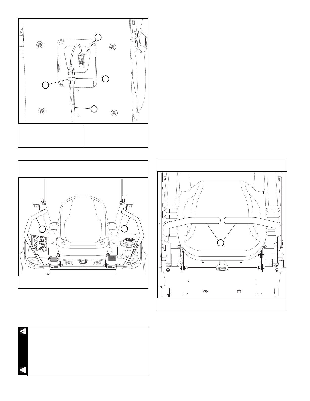
•Disconnect the mower harness from the seat
switch.
•Bypass the seat switch by connecting the two
mower harness female spades connectors
together. Figure 4-1 & Figure 4-2
•Re-attach the seat platform to the mower frame.
4. Loosen the jam nuts on each end of the steering
control rod assemblies. Figure 4-5
5. Set both steering control levers in the park brake
position. Figure 4-3
NOTE: Both steering control levers need to be in the park
brake position when starting the engine but need to be
moved rapidly out of the park brake position once engine
is started so that the brakes do not fight the
transmissions since they have not yet been adjusted.
This procedure will require that the unit to be
raised to allow the drive wheel to rotate.
•Block the mower up off of the ground using
only appropriate vehicle stands (minimum
weight rating of 2000 pound)s. Use in pairs
only. Follow the instructions supplied with
the vehicle stands.
•Do not allow the wheels to come in contact
with the floor or any object that would permit
the unit to propel itself.
•To prevent injury stay clear and exercise
caution when rotating the wheels.
Exercise extreme caution when the transmissions
are engaged.
•Keep hands, hair, clothing, etc., clear of the
cooling fans on top of the transaxles to
prevent entanglement.
WARNINGWARNING
Untrained maintenance personnel should never
attempt to make any adjustments or repairs to the
mower’s drive system while the engine is running.
The following procedures should be performed by
trained maintenance personnel only.
A. Seat switch
B. Female spade
connectors
C. Mower harness
Figure 4-1
WARNING
A
B
B
C
REV E 4-2 121366
6. Start the engine. Move the steering control lever to
barely engage the brake (neutral) slot and hold it in
that position (Do not engage the steering control lever
far enough to engage the brakes in the brake slot).
7. Beginning with the right side of the mower:
•Adjust the steering control rod so that the right
side wheel starts rotating forward while holding
the steering control lever in the neutral position.
•Adjust the steering rod back the opposite
direction to the point when the wheel stops
rotating.
•From that point, turn the steering rod back again
½ turn. This ensures that the steering rod is
adjusted so that the transmission control arm is
centered in the neutral band of the transmission.
Figure 4-6
•Move the steering control lever forward and
backward making sure that the wheel rotates
forward and backward correctly.
•Return the steering control lever to neutral and
re-check to make sure the wheel has stopped in
the neutral position.
•Place the steering control lever in the park brake
position. If neutral is set properly, you should not
hear the transmission whine.
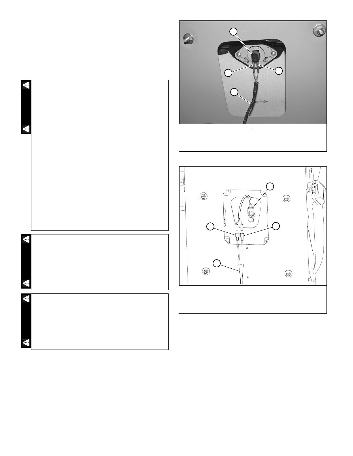
8. Repeat steps 4 through 7 for the left side.
A. Seat switch
B. Female spade
connectors
C. Mower harness
Figure 4-2
Shown with steering control levers in the park brake
position
A. Steering control lever
Figure 4-3
This operation is extremely dangerous. Pay close
attention when adjusting the steering control rod
so you do not get your fingers, tools, or anything
else close to the transaxle’s cooling fans.
A
B
B
C
AA
WARNING
Shown with steering control levers in the neutral position
A. Steering control lever
Figure 4-4
A

121366 4-3 REV E
9. Once both sides are properly adjusted, check them
together to make sure everything is working properly.
10. IMPORTANT: Unbolt the seat platform from the mower
frame.
•Disconnect the two female spade connectors
from each other (from step #3).
•Reconnect the two female spade connectors to
the seat switch. This must be completed so that
the safety circuit is functioning properly.
Figure 4-1
•Re-attach the seat platform to the mower frame.
11. The steering control levers should be adjusted so that
they align within ± .125" (± 3.2mm) of each other when
in the neutral position. Figure 4-6
NOTE: The space between the ends of steering control
handles should be .50” ±.25” (12.2mm ± 6.35mm).
Figure 4-6
12. Check to make sure all tools or obstructions are
removed from under the mower.
13. Raise the rear of the mower and remove the jack
stands. Lower the mower.
14. Remove the chocks from the front wheels.
Park Brake Spring Adjustment
Occasionally check the park brake spring adjustment using
the following method:
1. This procedure does not require engine power,
therefore:
•Park the mower on level ground
•Disengage the deck clutch.
•Place the steering control levers in the park brake
position.
•Stop the engine.
•Remove the ignition key.
•Disconnect the negative battery cable.
Shown with steering control lever in the neutral position
A. Steering control lever
B. Jam nuts
C. Steering control rod
D. Transaxle cooling fan
Figure 4-5
Do not operate the mower without plugging the
mower’s wiring harness into the seat switch. This
switch is an important part of the safety start
interlock system. Serious injury can result if the
seat switch is not plugged into the mower’s wiring
harness.
Never operate the mower with a non-functioning
seat switch. Always reconnect the seat switch to the
mower harness.
B
C
A
D
WARNINGWARNING
Never operate the mower with the seat platform
improperly secured. The seat platform must be
securely latched/bolted to prevent the seat from
moving/tilting in the event of mower tipping or
rollover.
Figure 4-6
WARNING
Align handles
± .125”
.50" ± .25”

REV E 4-4 121366
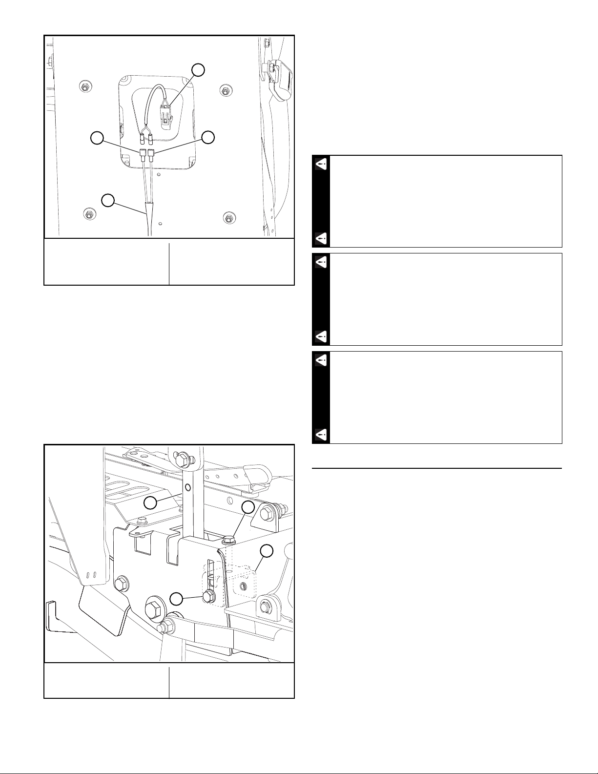
2. On one side measure the park brake spring. It should
be compressed to 1.43"–1.48" (36.3–37.6mm). If it is
not, adjust the nylock nut until the proper spring
compression is achieved. Figure 4-7
3. Repeat for other side.
4. Reconnect the negative battery cable.
Steering Control Lever Stops
IMPORTANT: Make sure the hydraulic system oil is at
operating temperature before beginning this procedure.
1. Raise the rear of the mower and block with certified
jack stands. The rear wheels need to be able to rotate
freely and clear of all obstructions.
2. Chock the front tires.
3. Unbolt the seat platform from the mower frame.
•Disconnect the mower harness from the seat
switch.
•Bypass the seat switch by connecting the two
mower harness female spade connectors
together. Figure 4-8 & Figure 4-9
•Re-attach the seat platform to the mower frame.
4. Start the engine. Move both steering control levers
forward against the stops located inside the steering
covers.
5. Determine if the drive wheels are rotating equally. If
one is rotating faster that the other proceed to the next
step.
6. Return the steering control levers to the park brake
position and shut the engine off.
A. Nylock nut
B. Park brake spring
C. Park brake rod
Figure 4-7
This procedure will require that the unit to be
raised to allow the drive wheel to rotate.
•Block the mower up off of the ground using
only appropriate vehicle stands (minimum
weight rating of 2000 pound)s. Use in pairs
only. Follow the instructions supplied with
the vehicle stands.
•Do not allow the wheels to come in contact
with the floor or any object that would permit
the unit to propel itself.
•To prevent injury stay clear and exercise
caution when rotating the wheels.
Exercise extreme caution when the transmissions
are engaged.
•Keep hands, hair, clothing, etc., clear of the
cooling fans on top of the transaxles to
prevent entanglement.
A
B
1.43"–1.48"
C
WARNINGWARNING
Untrained maintenance personnel should never
attempt to make any adjustments or repairs to the
mower’s drive system while the engine is running.
The following procedures should be performed by
trained maintenance personnel only.
A. Seat switch
B. Female spade
connectors
C. Mower harness
Figure 4-8
WARNING
A
B
B
C
121366 4-5 REV E
7. Loosen the side cap screw on the outside of the
steering cover on the side that is rotating to fast.
Tighten the top cap screw to adjust the drive-straight
bracket up. This allows the steering control lever to
make contact with the drive-straight bracket sooner.
Repeat until both drive wheels are rotating at the same
speed. Figure 4-10
8. Tighten the side cap screws on both the left and right
sides to lock the drive-straight brackets in place. Snug
the top cap screws to prevent loosening during
operation. Figure 4-10
9. IMPORTANT: Unbolt the seat platform from the mower
frame.
•Disconnect the two female spade connectors
from each other (from step #3).
•Reconnect the two female spade connectors to
the seat switch. This must be completed so that
the safety circuit is functioning properly.
Figure 4-8
•Re-attach the seat platform to the mower frame.
Belts
Inspect belts frequently for wear and serviceability.
Replace a belt that shows signs of:
•severe cuts
•tears
•separation
•weather checking
•cracking
•burns caused by slipping.
Slight raveling of belt covering does not indicate failure,
trim ravelings with a sharp knife.
Inspect the belt pulley grooves and flanges for wear. A new
belt, or one in good condition, should never run against the
bottom of the groove. Replace the pulley when this is the
case, otherwise, the belt will lose power and slip excessively.
Never pry a belt to get it on a pulley as this will cut or
damage the fibers of the belt covering.
Keep oil and grease away from belts, and never use belt
dressings. Any of these will destroy the belt composition in a
very short time.
A. Seat switch
B. Female spade
connectors
C. Mower harness
Figure 4-9
A. Top cap screw
B. Side cap screw
C. Drive-straight bracket
D. Steering control lever
Figure 4-10
A
B
B
C
A
D
B
C
Do not operate the mower without plugging the
mower’s wiring harness into the seat switch. This
switch is an important part of the safety start
interlock system. Serious injury can result if the
seat switch is not plugged into the mower’s wiring
harness.
Never operate the mower with a non-functioning
seat switch. Always reconnect the seat switch to the
mower harness.
Never operate the mower with the seat platform
improperly secured. The seat platform must be
securely latched/bolted to prevent the seat from
moving/tilting in the event of mower tipping or
rollover.
WARNINGWARNINGWARNING
REV E 4-6 121366
Hydraulic Pump Belt Adjustment
The transmission drive belt tension remains constant by
means of a tension idler and spring. There is no tension
adjustment of this belt. Figure 4-11
IMPORTANT: Inspect the belt every 100 hours and replace
as needed. Replace the belt every 200 hours or every two (2)
years whichever comes first.
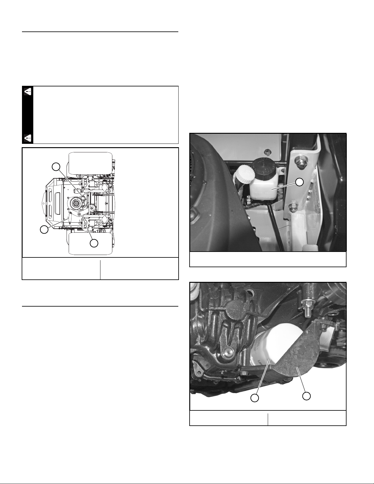
Hydraulic System
This mower is equipped with two integrated hydrostatic
transmissions (transaxles). Figure 4-12
IMPORTANT: Never use hydraulic or automatic
transmission fluid in this system; use only the specified
motor oil. Remember, dirt is the primary enemy of any
hydraulic system.
Each transaxle has its own hydraulic expansion tank. The
tanks are located in front of the engine and behind the
operator’s platform. Figure 4-12
Check the oil level in the hydraulic system after every 50
hours of operation or weekly, whichever occurs first. Check
more often if the system appears to be leaking or otherwise
malfunctioning.
The mower ships from the factory with SAE 20W50 motor oil
in the system. Use SAE 20W50 motor oil, 15W50 synthetic oil,
or 20W50 synthetic oil when changing the system oil and filter.
When the hydraulic system oil is cold, the fluid level should
be at the “Full Cold” line on the expansion tank.
Initial system oil and filter change must be after the first 75
hours of use or 1 year whichever comes first. Thereafter,
replace filter and oil in each transaxle every 2 years or 200
hours, whichever comes first.
Each transaxle’s filter is located per Figure 4-13. A
standard oil filter wrench is used to change filter. The
threads are right handed. Use a BigDog®Mowers approved
filter element only.
NOTE: The filter guard must be removed to access the
filter. Figure 4-13
IMPORTANT: When washing the mower, direct the spray
away (especially if using a power washer) from the
transaxle’s seals to prevent water intrusion and to ensure
component performance.
If the transmission belt fails, loss of control will
occur especially when operating on a slope. If you
lose steering control while operating the machine,
place the steering control levers in the park brake
position immediately. Inspect the machine and
involve your dealer to resolve the problem.
A. Tension idler
B. Hydraulic pump belt
C. Spring
Figure 4-11
WARNING
B
A
C
A. Expansion tank
Figure 4-12
A. Filter B. Filter guard
Figure 4-13
A
AB

121366 4-7 REV E
Fluid changing procedure
1. Park the unit on a level surface.
•Place the steering control levers in the park brake
position.
•Disengage the deck clutch.
•Remove the ignition switch key.
•Disconnect the negative battery cable.
2. Remove the three 1/4” filter guard screws and filter
guard. Clean any loose debris from around the filter.
Figure 4-14
3. Place an oil drain pan beneath the oil filter and remove
the oil filter from the transaxle.
4. After the oil has been drained, wipe the filter base
surface off and apply a film of new oil to the gasket of
the new replacement filter.
5. Install the new filter by hand, turn 3/4 to one full turn
after the filter gasket contacts the filter base surface.
6. Re-install the filter guard with three 1/4” screws.
Torque the screws to 65 in.–lbs. each. Figure 4-14
7. Repeat steps 2–6 for the opposite side transaxle.
8. Drain oil filters of all free flowing oil prior to disposal.
Place used oil in appropriate containers.
9. IMPORTANT: Remove the top port plug from both
transaxles prior to filling with oil. This will allow the
transaxles to vent during oil fill. Figure 4-15
10. Remove the cap from the transaxle's expansion tank.
NOTE: Fill with SAE 20W50 motor oil, 15W50 synthetic
oil or 20W50 synthetic oil until oil just appears at the
bottom of each transaxles top port (approximately 2
qts. per transaxle). Install the top port plug into each
transaxle. Torque plugs to 180 in.–lbs. Clean up any
oil that leaked from the ports. Figure 4-15
11. Continue to fill the transaxles through the expansion
tank until the “Full Cold” line is reached on the
expansion tank.
12. Re-install the expansion tank cap by hand. Be careful
not to overtighten.
13. Proceed to the purge procedure.
IMPORTANT: Purging procedures must be followed after
changing the oil and filter. Refer to Purging Procedure section
for detailed information.
IMPORTANT: When washing the mower, direct the spray
away (especially if using a power washer) from the transaxle’s
seals to prevent water intrusion and to ensure component
performance.
Purging procedure
Due to the effects air has on efficiency in hydrostatic drive
applications, it is critical that air is purged from the system.
Air creates inefficiency because its compression and
expansion rate is higher than that of the oil approved for use
in hydrostatic drive systems.
These purge procedures should be implemented any time a
hydrostatic system has been opened to facilitate
maintenance or the oil has been changed.
The resulting symptoms in hydrostatic systems may be:
1. Noisy operation.
2. Lack of power or drive after short term operation.
3. High operation temperature and excessive expansion
of oil.
Before starting, make sure the transaxle is at the proper oil
level. If it is not, fill to the specifications outlined in this
manual.
A. Screw
B. Filter
C. Filter guard
Figure 4-14
BC
A
A
A. Top port plug
Figure 4-15
A
REV E 4-8 121366
The following procedures are best performed first with the
vehicle drive wheels off the ground and then repeated under
normal operating conditions. If this is not possible, then the
procedure should be performed in an open area free of any
objects or bystanders.
1. Raise the rear of the mower and block with certified
jack stands. The rear wheels need to be able to rotate
freely and clear of all obstructions.
2. Chock the front tires.
3. Unbolt or unlatch the seat platform from the mower
frame.
•Disconnect the mower harness from the seat
switch.
•Bypass the seat switch by connecting the two
mower harness female spade connectors
together. Figure 4-16 & Figure 4-17
•Re-attach the seat platform to the mower frame.
4. Start the engine.
5. Position the steering control lever in the neutral
position.
IMPORTANT: Make sure the deck clutch switch is in
the “OFF” (disengaged) position. Figure 4-5
6. With the bypass valve open and the engine running,
slowly move the steering control lever in both forward
and reverse directions (5 or 6 times). Figure 4-19
7. With the bypass valve closed and the engine running,
slowly move the steering control lever in both forward
and reverse directions (5 or 6 times). Check the oil
level, and add oil as required after stopping the engine.
Never work under the machine or attachment
unless it is safely supported with jack stands.
•Make certain machine is secure when it is
raised and placed on the jack stands.
• Use only certified jack stands. Use only
appropriate jack stands, with a minimum
weight rating of 2000 pounds (907 kg) to
block the unit up.
•Use in pairs only.
•Follow the instructions supplied with the
jack stands.
•The jack stands should not allow the
machine to move when the engine is running
and the drive wheels are rotating.
•Do not allow the wheels to come in contact
with the floor or any object that would permit
the unit to propel itself.
•To prevent injury stay clear and exercise
caution when rotating the wheels.
Exercise extreme caution when the transmissions
are engaged.
•Keep hands, hair, clothing, etc., clear of the
cooling fans on top of the transmissions to
prevent entanglement.
Untrained maintenance personnel should never
attempt to make any adjustments or repairs to the
mower’s drive system while the engine is running.
The following procedures should be performed by
trained maintenance personnel only.
WARNINGWARNINGWARNING
A. Seat switch
B. Female spade
connectors
C. Mower harness
Figure 4-16
A. Seat switch
B. Female spade
connectors
C. Mower harness
Figure 4-17
A
B
B
C
A
B
B
C
Table of contents
Other BigDog Mower Lawn Mower manuals


