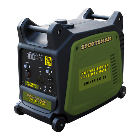
BILT HARD TGA-0253 User manual

TGA-0253Dual Fuel Inverter Generator

TABLE OF CONTENTSIntroduction..........................................1 Introduction................................................. 1 Portable Power Generator.................................1 This Booklet..................................................1Specifications........................................2Manual Conventions................................3Safety Rules..........................................4 Fuel Safety...................................................6Controls and Features..............................7 Inverter........................................................7 Parts Included...............................................7 Power Panel..................................................8Assembly..............................................9 Remove the Generator from the Shipping Carton...9 Connect the Battery........................................9 Add Engine Oil..............................................9 Add Fuel (Gas).............................................10 Connecting the Propane (LPG) Cylinder.............11 Grounding...................................................11 Operation at High Altitude..............................12Operation............................................13 Start the Inverter..........................................14 Fuel Selector Switch.....................................14 Before Starting the Generator..........................14 Electric Start(GAS).......................................14 Manual Choke Start(GAS)...............................15 Electric Start(LPG).......................................16 Manual Choke Start(LPG)...............................16 Connecting Electrical Devices.........................18 Connecting Electrical Loads...........................18 Do Not Overload Generator..............................18 Capacity..................................................18 Power Management....................................18 Economy Control Switch.................................19 12V DC outlet...............................................19 Battery Charging.............................................19 Stopping the Engine(GAS)...............................20 Stopping the Engine(LPG)...............................20Maintenance and Storage....................21 Overload Operation...................................21 Engine Maintenance..................................21 Oil......................................................21 Spark Plugs..........................................22 Air Filter..............................................22 Cleaning..............................................22 Clean the Spark Arrestor..........................23 Adjustments.........................................23 Maintenance Schedule...........................23 Generator Maintenance...........................23 Battery Maintenance/Storage...................24 To reinstall/replace the battery..................24Transportation and Storage....................25 Transporting the Generator..........................25 Storing the Generator.................................25 Product Disposal...........................................25Troubleshooting.................................26Parts Diagram....................................27Parts List..........................................28Engine Parts Diagram..........................29Engine Parts List................................30

OurTGA-02531

SPECIFICATIONSGeneratorOutputReceptacles120V AC, 60 Hz, 33.3 A, 1 Phase12V DC, 8.3 A 4000 Running Watts(Gasoline)3700 Running Watts(Propane)5500 Maximum Starting Watts120V 20A Duplex (5-20R)120V 30A (TT-30R/RV)12V DC AutomotiveDisplacementCompression RatioEngine TypeCooling SystemFuelEngine OilRun Time @ 25% Loadwith full tankSound Level at 23 feet, 75% loadBore x StrokeSpark PlugValve ClearanceEngine Speed224 cc9.1:1Horizontal Single Cylinder4-stroke, OHVForced air cooledTypeCapacity87+ octane, stabilizer-treatedunleaded gasoline3.17 Gallon(12L)Type SAECapacity10W-3012 hr68 dB72 mm x 55 mmTypeGapIntakeExhaustF7RTC0.022"– 0.026"0.004"– 0.006"0.004"– 0.006"3800 RPMThe emissions control system for this Engine is warranted for standards set by theU.S. Environmental Protection Agency and by the California Air Resources Board (also known as CARB).For warranty information, refer to the last pages of this manual.203(600ml). fl. oz.2

3

0004

5

6

7Automotive style USB adapterLPG Hose With RegulatorNever Flat Wheels(5)(6)3645

8156789101112131416(12)(13)(14)FUEL STATUS INDICATOR –Red light ashes when the fuel supply is abnormal.(2)(3)(4)(5)120 Volt AC, 20 Amp Duplex (NEMA 5-20R) –May be used to supply electrical power for theoperation of 120 Volt AC, 20 Amp, single phase60 Hz electrical loads.120 Volt AC, 30 Amp Receptacle (NEMA TT-30R)– May be used to supply electrical power for theoperation of 120 Volt AC, 30 Amp, single phase60 Hz electrical loads.(6)Parallel Outlets-used for parallel operation.Fuel Valve KnobEngine SwitchLPG Hose Quick Connect InletBattery Switch(15)15(16)LPGRed light flashes when the fuel s uppl y is abnormalFUEL STATUS INDICATORCAUTION:DO NOT disconnect parallel cables while generator is running PARALLEL OPERATING SYSTEMONOFFECONOMYAC RESETCIRCUIT BREAKERDCCIRCUIT BREAKERSONOFF Disconnect while stop using LPGCAUTION:LPGGASAC 120VAC 120V8A30A20ADC 12V 8.3AOVERLOADOUTPUT123START-Start ModeON-Standby Mode-OFF-Stop ModeGAS OFFReset-When you’ve overloaded the generator, the overload light will stay on and cut off the output in 3 to 30 seconds, depending on the load. Reduce the load by turning off and disconnecting your electrical device(s) press the reset button to reset the circuit. If no power is produced after resetting, turn off and disconnect all electrical devices andrestart your generator.circuit breaker will activate when the NEMA 5-20 outlets exceed 20A.The 30-amp AC circuit breaker will activate when the NEMA TT-30R outlets exceed 30A.The 8-amp DC circuit breaker will activate when the DC 12V and USB outlets exceed 8A. When the circuit breaker activates, turn off and disconnect the device from its respective outlet, and press the circuit breaker to reset.The 20-amp AC

9Turn the knob from lock to open.Then remove the maintenance cover.(A)2. Take off the SAE sheath, then connect two SAE wires.nearby Add 0.6L of oil and replace oil fill cap/dipstick.Turn the knob from lock to open.Then remove the maintenance cover.

1087Add fuel until reach the red line.87Add fuel until reach the red line.

11LPGopen the LPG quick connect cover thenLPGGASGAS OFF

12Follow instructions in a well-ventilated area away from ignition sources.If the engine is hot from use, shut the engine off and wait for it to cool before proceeding. Do not smoke.At high altitudes, the engine’s carburetor, governor (if so equipped), and any other parts that control the fuel-airratio will need to be adjusted by a qualified mechanic to allow efficient high-altitude use and to prevent damage to the engine and any other devices used with this product. The fuel system on this engine may be influenced by operation at higher altitudes. Proper operation can be ensured by installing an altitude kit at (not included)altitudes higher than 3000 ft. above sea level. At elevations above 8000 ft, the engine may experience decreased performance, even with the proper main jet. Operating this engine without the proper altitude kit installed may increase the engine's emissions and decrease fuel economy and performance. The kit should be installed by a qualified mechanic.Warranty void if necessary adjustments are not made for high altitude use.NOTICE1. Turn off the engine.2. Close the fuel valve.3. Place a bowl under the fuel cup to catch any spilled fuel.4. Unthread the bolt holding the fuel cup.5. Remove the bolt, Bolt Seal, fuel cup, Fuel Cup Seal and Main Jet from the body of the carburetor assembly.A carburetor screwdriver (not included) is needed to remove and install the Main Jet.6. Replace the Main Jet with the replacement Main Jet needed for your altitude range(1a). 7. Replace the Fuel Cup Seal (3a), fuel cup, Bolt Seal (2a), and bolt. Tighten in place. 8. Wipe up any spilled fuel and allow excess to evaporatebefore starting engine. To prevent FIRE, do not start the engine while the smell of fuel hangs in the air. Carburetor bowl may have gas in it which will leak upon removing the bolt.The mixing tube is held in place by the Main Jet and might fall out when it is removed.If it falls out, replace it in the same orientation before replacing the Main Jet.The Fuel Cup Seal and Bolt Seal may be damaged during removal and should be replaced with the new ones from the kit.Do not cross thread bolt when tightening.Finger tighten first and then use a wrench to make sure the bolt is properly threaded.High Altitude Kit Parts List - A PartDescriptionQty1a2a3aMain Jet 3000-8000 ft.Bolt SealFuel Cup Seal111NOTICEO-Ring

Generator should only be connected to electrical devices, either directly or with an extension cord. NEVER connect to a building electrical system without a qualified electrician and connected to a transfer switch as a separately derived system. Such connections must comply with local electrical laws and codes.Failure to comply can create a back-feed, which may result in serious injury or death to utility workers.To maximize safety, ALWAYS ground the generator before using it. See section "Grounding”.Use a ground fault circuit interrupter (GFCI) in highly conductive areas such as metal decking or steel work. GFCIs are available in-line with some extension cords.Disconnect all electrical loads from the generator before attempting to start.Follow the instructions on the next page to start your generator. Using a generator indoors CAN KILL YOU IN MINUTES. Generator exhaust contains carbon monoxide (CO). Thisis a poison gas you cannot see or smell. If you can smellthe generator exhaust, you are breathing CO. But even if you cannot smell the exhaust, you could be breathing CO.NEVER use a generator inside homes, garages, crawl spaces, or other partially enclosed areas. Deadly levels of carbon monoxide can build up in these areas. Using a fan or opening windows and doors does NOT supply enough fresh air. ONLY use a generator outside and far away from windows, doors, and vents. These openings can pull in generator exhaust.Even if you use a generator correctly, CO may leak into the home. ALWAYS use a battery-powered or batterybackup CO alarm in the home. If you start to feel sick, dizzy, or weak after the generator has been running,move to fresh air RIGHT AWAY. See a doctor. You may have carbon monoxide poisoning.The exhaust from this product contains chemicals known to the State of California to cause cancer, birth defects, or other reproductive harm.Do not operate generator near open flame or flammable materials. This generator may emit highly flammable and explosive gasoline vapors, which can cause severe burns or even death if ignited. A nearby open flame can lead to explosion even if it isn’t directly in contact with gasoline.Do not smoke near the generator.This generator produces powerful voltage, which can result in electrocution. Do not use in rainy or wet conditions. Do not touch bare wires or receptacles (outlets). Do not allow children or non-qualified persons to operate.13

GASLPGGASLPGGASGAS OFF14Before Starting the Generator1. Verify that generator is outside on a dry, level surface with at least two feet of clearance on all sides.2. To maximize safety, check that the generator is properly grounded.3. Check there is sufficient level of oil in the crankcase. Add oil if necessary.4. Make sure there is sufficient level of gasoline in the fuel tank.Add fuel if necessary.5. Make sure all electrical devices are unplugged from the generator during ignition. Otherwise it will be difficult for the engine to start.Electric Start(GAS)LPGGASGAS OFFGASLPGGASGAS OFFLPGLPGLPG

157.Turn the choke lever to the “CHOKE” (right) position. 8. Pull the starter cord slowly until resistance is felt and then pull rapidly.6.Turn the knob from lock to open.Then remove the maintenance cover.(A)6. Press and hold the ignition switch to the “START” position. Release as the engine begins to roll over. If the engine fails to start within five seconds, release the switch and wait at least ten seconds before attempting to start the engine again.If the battery is dead or not able to produce enoughcurrent to power the push button choke, the choke itselfcan be operated manually to help start the engine. Tomanually choke and start the inverter, follow these steps:Manual Choke Start(GAS)LPGGASGAS OFFGASTurn the battery switch to the “ON” position.Turn the battery switch to the “ON” position.(To recharge the battery after the generator runs.)9. After the generator is started, the will choke lever automatically run to the working position, without manually flicking the choke lever.ON.ON.

16LPGopen the LPG quick connect cover then7. Press and hold the ignition switch to the “START” position. Release as the engine begins to roll over. If the engine fails to start within five seconds, release the switch and wait at least ten seconds before attempting to start the engine again.Electric Start(LPG)Manual Choke Start (LPG)LPGGASGAS OFFLPGopen the LPG quick connect cover thenLPGGASGAS OFF
Turn the battery switch to the “ON” position.If the battery is dead or not able to produce enoughcurrent to power the push button choke, the choke itselfcan be operated manually to help start the engine. Tomanually choke and start the inverter, follow these steps:Turn the battery switch to the “ON” position.(To recharge the battery after the generator runs.)ON.ON.

177.Turn the choke lever to the “CHOKE” (right) position. 8. Pull the starter cord slowly until resistance is felt and then pull rapidly.6.Turn the knob from lock to open.Then remove the maintenance cover.(A)9. After the generator is started, the will choke lever automatically run to the working position, without manually flicking the choke lever.

18Connecting Electrical DevicesWhen the rated wattage requirement of each electrical device has been determined, add these numbers to find the total rated wattage needed. If this number exceeds the rated wattage of the generator, DO NOT connect all these devices. Select a combination of electrical devices with a total rated wattage lower than or equal to the rated wattage of the generator.12060to make sure start ONLY one device each time.Check the power indicator light (green).Check the power indicator light (green).
Table of contents
Popular Portable Generator manuals by other brands

National Instruments
National Instruments PXIe-5654 CALIBRATION PROCEDURE

Gude
Gude GSE 6700 Translation of original operating instructions

Porter-Cable
Porter-Cable DTE325 instruction manual

MOLEAER
MOLEAER CLEAR Installation and startup guide

Keysight Technologies
Keysight Technologies X Series Installation note

National Instruments
National Instruments NI 5412 Specifications