ELTEX POWER CHARGER PC User manual

Operating Instructions
F01064y
High voltage generator
POWER CHARGER PC
BA-en-3041-2008

2BA-en-3041-2008_PC

BA-en-3041-2008_PC 3
Content
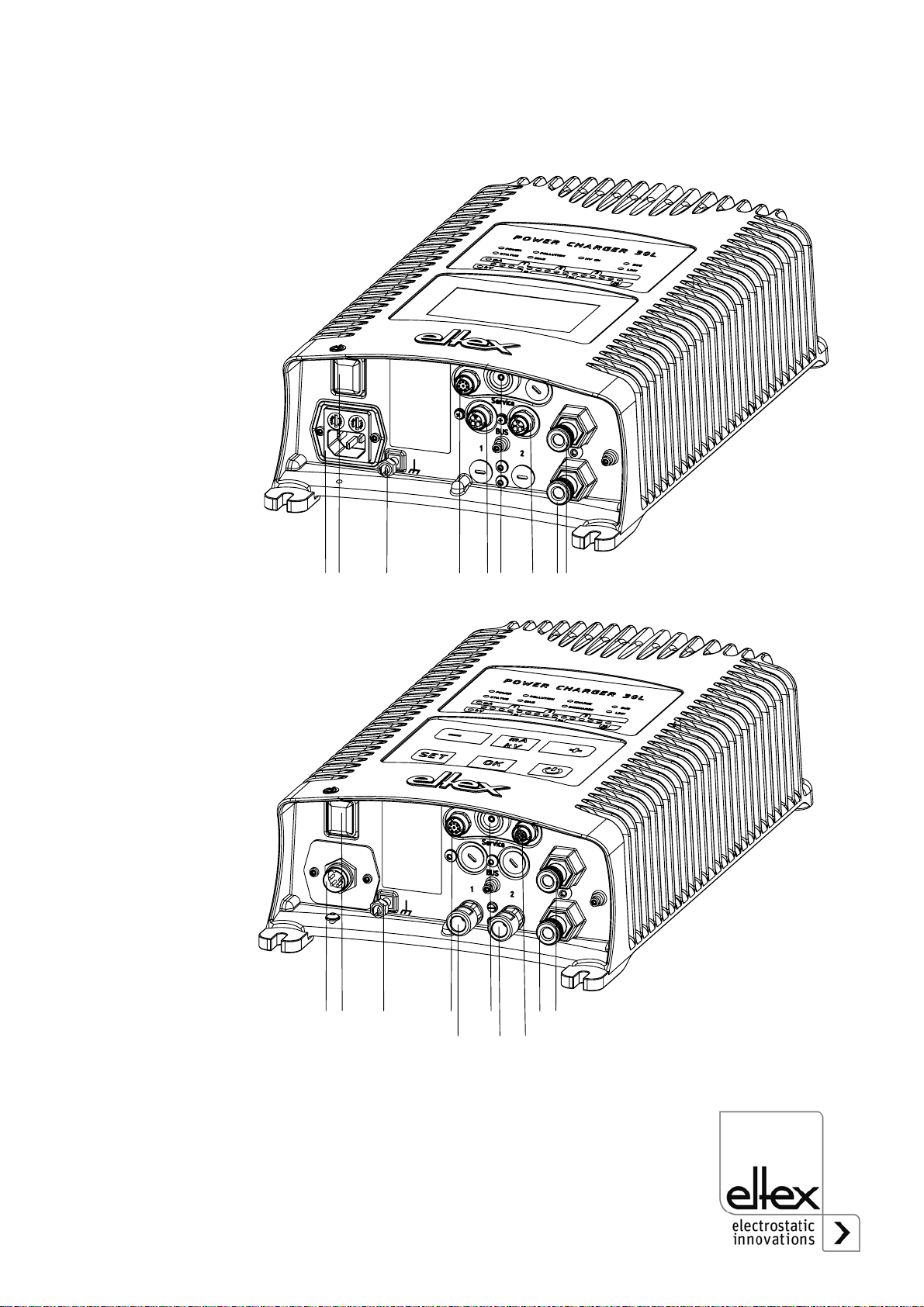
1 Outline of Appliance . . . . . . . . . . . . . . . . . . . . . . . . . . . . . . . . . . . 7
1.1 Variants . . . . . . . . . . . . . . . . . . . . . . . . . . . . . . . . . . . . . . . . . . . . . . 9
1.2 High voltage setting range . . . . . . . . . . . . . . . . . . . . . . . . . . . . . . . 10
2 Safety . . . . . . . . . . . . . . . . . . . . . . . . . . . . . . . . . . . . . . . . . . . . . . 12
2.1 Identification of risks and hazards . . . . . . . . . . . . . . . . . . . . . . . . . 12
2.2 Contact protection . . . . . . . . . . . . . . . . . . . . . . . . . . . . . . . . . . . . . 12
2.3 Technical advance . . . . . . . . . . . . . . . . . . . . . . . . . . . . . . . . . . . . .12
2.4 Proper Use . . . . . . . . . . . . . . . . . . . . . . . . . . . . . . . . . . . . . . . . . .13
2.5 Work and operational safety . . . . . . . . . . . . . . . . . . . . . . . . . . . . . 13
3 Installation . . . . . . . . . . . . . . . . . . . . . . . . . . . . . . . . . . . . . . . . . . 17
3.1 Assembly of the high voltage generator . . . . . . . . . . . . . . . . . . . . 17
3.2 Ground connection . . . . . . . . . . . . . . . . . . . . . . . . . . . . . . . . . . . . 18
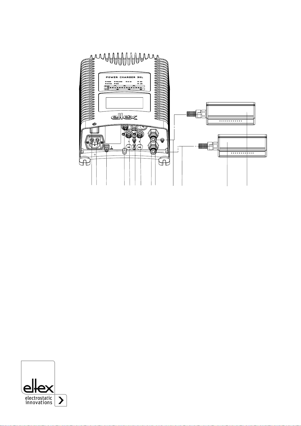
3.3 Installation of the high voltage cables . . . . . . . . . . . . . . . . . . . . . . 19
3.4 Bars suitable for connection . . . . . . . . . . . . . . . . . . . . . . . . . . . . . 20
3.4.1 Charging bars suitable for connection. . . . . . . . . . . . . . . . . . . . . 20
3.4.2 Discharging bars suitable for connection . . . . . . . . . . . . . . . . . . 22
3.5 Connecting the charging bar to the high voltage generator . . . . . . 22
3.6 Connecting the discharging bar to the high voltage generator . . . 23
3.7 Disconnecting the high voltage cable . . . . . . . . . . . . . . . . . . . . . . 24
3.8 Connecting the supply voltage . . . . . . . . . . . . . . . . . . . . . . . . . . .24
3.8.1 Connecting the supply voltage 24 V DC . . . . . . . . . . . . . . . . . . 24
3.8.2 Connecting the supply voltage 90 - 264 V AC . . . . . . . . . . . . . . 25
3.9 Fieldbus Interface . . . . . . . . . . . . . . . . . . . . . . . . . . . . . . . . . . . . .25
3.9.1 CANopen® (optional) . . . . . . . . . . . . . . . . . . . . . . . . . . . . . . . . .26
3.9.2 ModbusTCP (optional) . . . . . . . . . . . . . . . . . . . . . . . . . . . . . . . .27
3.10 Analog Interface . . . . . . . . . . . . . . . . . . . . . . . . . . . . . . . . . . . . . . 28
3.10.1 Anlalog interface Charging . . . . . . . . . . . . . . . . . . . . . . . . . . . . . 28
3.10.2 Analog interface Discharging . . . . . . . . . . . . . . . . . . . . . . . . . . .30
3.11 Use of the Eltex signal cable CS and mains cable KN. . . . . . . . . . 31
4 Operation . . . . . . . . . . . . . . . . . . . . . . . . . . . . . . . . . . . . . . . . . . . 34
4.1 Startup . . . . . . . . . . . . . . . . . . . . . . . . . . . . . . . . . . . . . . . . . . . . . . 34
4.2 Function monitoring . . . . . . . . . . . . . . . . . . . . . . . . . . . . . . . . . . . .35
4.2.1 Variants with CANopen® (optional) . . . . . . . . . . . . . . . . . . . . . . 38
4.2.2 Variants with ModbusTCP (optional). . . . . . . . . . . . . . . . . . . . . . 39
4.3 Realising the high voltage . . . . . . . . . . . . . . . . . . . . . . . . . . . . . . . 41
4.4 Integrated control elements . . . . . . . . . . . . . . . . . . . . . . . . . . . . . .42
4.4.1 Using he membrane keyboard . . . . . . . . . . . . . . . . . . . . . . . . . . 42

4BA-en-3041-2008_PC
4.4.2 Using the display . . . . . . . . . . . . . . . . . . . . . . . . . . . . . . . . . . . . .53
4.4.2.1 Release . . . . . . . . . . . . . . . . . . . . . . . . . . . . . . . . . . . . . . . . . . .54
4.4.2.2 Configuration . . . . . . . . . . . . . . . . . . . . . . . . . . . . . . . . . . . . . . .54
4.4.2.2.1 ECC User . . . . . . . . . . . . . . . . . . . . . . . . . . . . . . . . . . . . . . . .55
4.4.2.2.2 Access Management . . . . . . . . . . . . . . . . . . . . . . . . . . . . . . .56
4.4.2.2.3 Settings. . . . . . . . . . . . . . . . . . . . . . . . . . . . . . . . . . . . . . . . . .57
4.4.2.2.4 Highlight Values . . . . . . . . . . . . . . . . . . . . . . . . . . . . . . . . . . .58
4.4.2.2.5 Factory Settings . . . . . . . . . . . . . . . . . . . . . . . . . . . . . . . . . . .58
4.4.2.3 Preset. . . . . . . . . . . . . . . . . . . . . . . . . . . . . . . . . . . . . . . . . . . . .59
4.4.2.4 Eltex DEBUG overview / Message overview. . . . . . . . . . . . . . .60
4.4.2.5 Parameter . . . . . . . . . . . . . . . . . . . . . . . . . . . . . . . . . . . . . . . . .61
4.4.2.6 General Parameter. . . . . . . . . . . . . . . . . . . . . . . . . . . . . . . . . . .62
5 Maintenance . . . . . . . . . . . . . . . . . . . . . . . . . . . . . . . . . . . . . . . . .63
5.1 High voltage generator . . . . . . . . . . . . . . . . . . . . . . . . . . . . . . . . . .63
5.2 Charging bars / Discharging bars . . . . . . . . . . . . . . . . . . . . . . . . . .63
6 Troubleshooting . . . . . . . . . . . . . . . . . . . . . . . . . . . . . . . . . . . . . .64
6.1 Error messages . . . . . . . . . . . . . . . . . . . . . . . . . . . . . . . . . . . . . . .64
6.2 Warning messages . . . . . . . . . . . . . . . . . . . . . . . . . . . . . . . . . . . .72
7 Warranty . . . . . . . . . . . . . . . . . . . . . . . . . . . . . . . . . . . . . . . . . . . .75
8 Technical Specifiations POWER CHARGER PC_ _ . . . . . . . . . .76
9 Dimensions . . . . . . . . . . . . . . . . . . . . . . . . . . . . . . . . . . . . . . . . . .79
10 Spare parts and accessories . . . . . . . . . . . . . . . . . . . . . . . . . . .80
11 Battery change / Decommissioning . . . . . . . . . . . . . . . . . . . . . .82
A Assembly of the plugs . . . . . . . . . . . . . . . . . . . . . . . . . . . . . . . . .83
A.1 Plug M16 for 24 V DC supply voltage
straight version, version with shield clamping ring . . . . . . . . . . . . .83
A.2 Plug for power cable for AC supply voltage . . . . . . . . . . . . . . . . .84
A.3 Plug M12, 8-pin for analog interface Charging . . . . . . . . . . . . . . . .85
A.4 Plug M12, 5-pin for analog interface Disharging . . . . . . . . . . . . . .85
Declaration of Conformity . . . . . . . . . . . . . . . . . . . . . . . . . . . . . . . . . .87

BA-en-3041-2008_PC 5
Dear customer,
The POWER CHARGER PC high voltage generator is a universal high
voltage supply unit for controlled charging and use of electrostatic effects.
The following bars may be connected:
Charge:
System variants PCSC, PCTL, PCRT und PCRM:
• R130A3 / R130A6
• R120 voltage limitation, note Operating Instructions R120
• R23ATR / R23ATR11
• EXR130A3 / EXR130A3L: only for generators of the following types:
PC_ _/ _ _ _ _ _ _ _E, PC_ _/ _ _ _ _ _ _ _D
voltage limitation, see table page 10
System variantee PCMT:
• R170A3 voltage limitation, see table page 10
Discharge:
• Variant "A" (not for Performance Level applications)
R50
EXR5C
• Variant "C"
R60
R60L
• Variant "P"
RG52
This document contains the general, cross-system operating instructions
for all generators of the POWER CHARGER family. For supplements, limi-
tations and particularities specific to your system, please see the appropri-
ate system manual.

6BA-en-3041-2008_PC
All generators of the POWER CHARGER PC family offer the following
features:
• Up to 50% higher charging power than comparable Eltex charging
generators
• Parallel control of charging voltage, charging current and charging
capacity
• Temperature-controlled power limitation
• Robust, compact design
• Easy installation
• Low weight
• Industry-grade high voltage plug connection
• Integrated function and error monitoring
• LED display for visualization of the operating status
• Touchscreen operation (optional)
• Easy setup via an analog interface
• Integration of the generator into CANopen® networks (optional)
• Industrial Ethernet support (optional)
Please read these instructions carefully before starting the unit. This will
help you prevent personal injuries and damage to property.
Simply give us a call if you have any suggestions, proposals or ideas for
improvements. We greatly appreciate the feedback from the users of our
appliances

BA-en-3041-2008_PC 7
1. Outline of Appliance
Fig. 1:
High voltage
generator
POWER
CHARGER
with field bus
Z-116035by_1
Fig. 2:
High voltage
generator
POWER
CHARGER
with discharge
Z-116035by_2

8BA-en-3041-2008_PC
1 Operating switch ON/OFF
2 System input 90 - 264 V AC
3 System input 24 V DC
4 Ground terminal
5 Analog interface Charge
6 Interface 1 Field bus
7 Service interface
8 Interface 2 Field bus
9 High voltage output: Connection of the charging bar
9.1High voltage output illustrated with a protective cap
10 High voltage cable
11 Charging bar
12 Analog interface Discharge
13 Hight voltage output Discharge
Fig. 3:
HIgh voltage
generator
POWER
CHARGER with
charging bars
suitable for
connection
Z-116035by_3

BA-en-3041-2008_PC 9
1.1 Variants
The high voltage generators of the POWER CHARGER PC family are
available in different variants. They can be combined depending on the
output voltage, polarity, output power and interfaces etc.
Reference code with the individual variables:
12345678 9
PC /
Article-No. Version Standard Version
1 Variable Discharge X
A
C
P
No Discharge
Active Discharge series R50 / EXR5C*
*not in combination with P, D under variable 8
Active Discharge series R60
Passive Discharge
2 Variable Polarity N
PNegative
Positive
3 Variable Voltage 3
630 kV-Version
60 kV-Version
4 Variable Supply /
Output power L
S
H
24 V DC, 75 W
Mains voltage 90 / 264 V AC, 75 W
Mains voltage 90 / 264 V AC, 150 W
5 Variable Accessory
Plug / Cable O
L
C
E
U
No plug / cable included
24 V plug
Plug for power cable, confectionable
Power cable with plug EU (CEE 7/7)
Power cable with plug NA (NEMA 5-15)
6 Variable Display X
DWithout Display
Display integrated
7 Variable Interface A
C
M
Analog interface
Analog interface + CANopen®
Analog interface + ModbusTCP
8 Variable Certification X
P
E
D
Without additional Certification
Performance Level d
Suitable for operation with Ex-bars
deviating max. output voltage, see table page 10
Suitable for operation with Ex-bars and Performance
Level d,
deviating max. output voltage, see table page 10
9 Variable Version 000 Standard Version

10 BA-en-3041-2008_PC
1.2 High voltage setting range
Depending on the selected variant, you can set different maximum values
for the output voltage, output current and output power.
Output voltage / - current for use in combination with
charging bars EXR130A3 / EXR130A3L / R170A3
Fig. 4:
Diagram
Depandance
Current / Voltage
F00058y
0
20
40
60
80
100
0 20 40 60 80 100
I [%]
U [%]
Variant Umin Umax Imin Imax
PC_ _/_N3L_ _ _E
PC_ _/_N3L_ _ _D
PC_ _/_N3S_ _ _E
PC_ _/_N3S_ _ _D
1.5 kV 27 kV 50 µA 3.75 mA
PC_ _/_N3H_ _ _E
PC_ _/_N3H_ _ _D 1.5 kV 27 kV 50 µA 7.5 mA
PC_ _/_P3L_ _ _E
PC_ _/_P3L_ _ _D
PC_ _/_P3S_ _ _E
PC_ _/_P3S_ _ _D
1.5 kV 18 kV 50 µA 3.75 mA
PC_ _/_P3H_ _ _E
PC_ _/_P3H_ _ _D 1.5 kV 18 kV 50 µA 7.5 mA
PCMT/_ _3L
PCMT/_ _3S 1.5 kV 18 kV 50 µA 3.75 mA
PCMT/_ _3H 1.5 kV 18 kV 50 µA 7.5 mA

BA-en-3041-2008_PC 11
Depandance current / voltage
Initial values min / max
Supply /
output power Variable output voltage
30 kV Variable output voltage
60 kV
L = 24 V DC, 75 W
S = 90/264 V AC, 75 W 3.75 mA at 20 kV
2.5 mA at 30 kV 1.875 mA at 40 kV
1.25 mA at 60 kV
H = 90/264 V AC, 150 W 7.5 mA at 20 kV
5 mA at 30 kV 3.75 mA at 40 kV
2.5 mA at 60 kV
Supply /
output power Variable output voltage
30 kV Variable output voltage
60 kV
L = 24 V DC, 75 W
S = 90/264 V AC, 75 W
Umin = 1.5 kV
Imin = 50 µA
Umax = 30 kV
Imax = 3.75 mA
Umin = 6 kV
Imin = 50 µA
Umax = 60 kV
Imax = 1.875 mA
H = 90/264 V AC, 150 W Umin = 1.5 kV
Imin = 50 µA
Umax = 30 kV
Imax = 7.5 mA
Umin = 6 kV
Imin = 50 µA
Umax = 60 kV
Imax = 3.75 mA

12 BA-en-3041-2008_PC
2. Safety
The units have been designed, built and tested using state-of-the-art engi-
neering, and have left the factory in a technically and operationally safe
condition. If used improperly, the units may nevertheless be hazardous to
personnel and may cause injury or damage. Read the operating instruc-
tions carefully and observe the safety instructions.
2.1 Identification of risks and hazards
Possible risks and hazards resulting from the use of the units are referred
to in these operating instructions by the following symbols:
Warning!
This symbol appearing in the operating instructions refers to operations
which, if carried out improperly, may result in serious personal injuries.
Caution!
This symbol appearing in the operating instructions refers to operations
which, if carried out improperly, may result in damage to property.
Ex Warning!
For units with EX approval only.
This symbol denotes the special conditions which must be observed when
operating the system in explosion hazard areas as specified in the EX
approvals.
2.2 Contact protection
The site of installation and/or use of the units is outside the control of
Eltex, contact protection against inadvertent contact of the bars and of live
components by personnel as specified by the employer’s liability insu-
rance association may have to be provided (e.g. DGUV V3 in Germany).
Contact protection devices made of conductive material must be
grounded.
2.3 Technical advance
The manufacturer reserves the right to make changes to the technical
specifications without prior notice in order to adapt the units to state-of-
the-art engineering. Eltex will provide the latest information on any
changes or modifications in the operating instructions on request.
Ex!

BA-en-3041-2008_PC 13
2.4 Proper Use
The POWER CHARGER PC high voltage generator has been approved
as operating voltage generator for the appropriate Eltex charging bars. It
must be operated only with the appropriate Eltex bars (see chapter Instal-
lation and Assembly for bar models).
If the unit is used in any other high voltage application, the manufacturer´s
warranty covers the safe use in terms of technical safety.
The manufacturers will not assume any liability and warranty if the units
are used improperly or used outside the intended purpose.
Modifications or changes made to the devices are not permitted.
Use only original Eltex spare parts and equipment.
2.5 Work and operational safety
Warning!
Carefully observe the following notes and the complete Chapter 2
"Safety”, page 12!
Always observe the rules and regulations applying in your country with
reference to electrical appliances.
• Before installation, carrying out repairs, cleaning or maintenance work
and before resetting the unit after malfunctions, switch off the high vol-
tage generator and disconnect the mains power supply on all units and
associated components (see Chapter 3 "Installation”, page 17, Chapter
5 "Maintenance”, page 63, Chapter 6 "Troubleshooting”, page 64).
• If electrically conductive substrates or substrates coated with conduc-
tive material (e.g. metal foil or metal composites) are used, the dis-
charging voltage of the generator must be switched.
• Before carrying out any work involving the units, the machine which has
the units fitted must not be in operation (see Chapter 3 "Installation”,
page 17, Chapter 5 "Maintenance”, page 63, Chapter 6 "Troubleshoot-
ing”, page 64).
• Any work involving the units must be carried out by qualified electri-
cians (see Chapter 3 "Installation”, page 17, Chapter 5 "Maintenance”,
page 63, Chapter 6 "Troubleshooting”, page 64, Chapter 11 "Battery
change / Decommissioning”, page 83).
• The unit may only be used by qualified personnel trained for explosion
hazard areas.
• A permanent grounding connection must be made and checked via the
ground terminal before the startup of the generator. The ground cable
should have a minimum cross section of 1.5 mm2and should be routed
with the shortest possible distance to the machine frame. If the length
of the cable is > 0.5 m, the cross section must be at least 2.5 mm2. The
ground connection must be permanently ensured for the entire opera-

14 BA-en-3041-2008_PC
ting time of the generator (see Chapter 3.2 "Ground connection”,
page 18).
• When routing the high voltage cables, observe Chapter 3.3 "Installation
of the high voltage cables”, page 19.
• The high voltage cable must be pushed up to the stop (150 mm) into
the cable inlet! The connecting area of the high voltage cable must be
kept clean (see Chapter 3.5 "Connecting the charging bar to the high
voltage generator”, page 22).
• If no charging/discharging bar is connected to the respective plug con-
nection of the generator, the connection must be closed with the blind
plug provided (see Chapter 3.5 "Connecting the charging bar to the
high voltage generator”, page 22, Chapter 3.6 "Connecting the dis-
charging bar to the high voltage generator”, page 23).
• In applications involving moving bars (e.g. film draw strips), the high
voltage cable must be attached such that there is no cable movement
near the connection zone of the power supply unit (see Chapter 3.5
"Connecting the charging bar to the high voltage generator”, page 22,
Chapter 3.6 "Connecting the discharging bar to the high voltage gener-
ator”, page 23).
• Due to the power consumption of the high voltage generator, the cable
cross-sections should be as large and the cables as short as possible
in order to reduce cable loss (see Chapter 3.8.1 "Connecting the supply
voltage 24 V DC”, page 24).
• The voltage at the individual contacts must not exceed 60 V DC (see
Chapter 3.8.1 "Connecting the supply voltage 24 V DC”, page 24,
Chapter 3.9 "Field bus Interface”, page 25).
• To prevent an interruption of the power supply due to vibrations or other
mechanical influences, Eltex recommends using latched sockets to
connect the power supply cable; see spare part no. 116329 (see Chap-
ter 3.8.2 "Connecting the supply voltage 90 - 264 V AC”, page 25).
• For the variant with CANopen®, a cable suitable for CAN bus networks
with a surge resistance of 120 ohms must be used for both bus leads;
this is the only way to ensure the proper functioning of the CAN network
(see Chapter 3.9.1 "CANopen® (optional)”, page 26).
• Generally, for the interface cables shielded cable should be used; the
shields must be placed on both sides (see Chapter 3.10.1 "Analog
interface Charging”, page 28, Chapter 3.10.2 "Analog interface Dis-
charging”, page 30).
• When using the optional Eltex signal cable CS or the mains cable KN,
the colour markings and the bending radii should be observed when
connecting the individual leads (see Chapter 3.11 "Use of the Eltex sig-
nal cable CS and mains cable KN”, page 31).

BA-en-3041-2008_PC 15
• Check the high voltage generator, all connected units, the electrical
wiring and the high voltage cables at regular intervals for any damage.
Any damaged components must be repaired or replaced before conti-
nuing to operate the unit, or the appropriate units must be disabled.
• Make sure that the bars are clean at all times. Dirt on the bars may
cause malfunctions and premature wear of the devices.
• Please note that for variants with active discharging and corresponding
parameterization of the discharge mode as “active”, the hardware
release for discharging must always precede the release for charging
(see Chapter 4.3 "Releasing the high voltage”, page 41).
• When cleaning the bars do not soak the bars in solvent and do not
damage the emission tips; allow the solvent to evaporate completely
before restarting the unit (see Chapter 5 "Maintenance”, page 63).
• The IP54 protection class applies only if the lid of the enclosure is
closed and the cable entries are covered.
• Before opening the generator, switch it off and disconnect all plug con-
nectors and cables (see Chapter 11 "Battery change / Decommission-
ing”, page 83).
• The operation of the bars can generate ozone. The ozone concentra-
tion levels developing near the bars depend on many different factors
such as site of installation, bar current and voltage, air circulation, etc.,
and can therefore not be specified in general terms.
If the maximum allowable concentration of ozone must be observed at
the site of installation of the bar, the concentration must be measured
on site.
The AGW value (maximum admissible concentration) serves to assess
the ozone concentration at the workplace. The user must make sure
that the appropriate national AGW value is at no times exceeded, e.g.
in Germany the ozone concentration occurring during the operation of
the system must not exceed the recommended value based on interna-
tional limits of 0.06 ml/m³ (0.12 mg/m³).
•Static on personnel
Static charges on personnel are unlikely if the bars are installed proper-
ly. Personnel must wear conductive footwear.
Please note all national regulations regarding electrostatic charge (e.g.
TRGS 727 in Germany).

16 BA-en-3041-2008_PC
Information on performance level applications:
• The 24 V DC power supply to be used must be tested according to the
EN 60950-1 or EN 62368-1 standard / must meet the applicable PELV
(protective extra low voltage) or SELV (safety extra low voltage)
requirements (see Chapter 3.8.1 "Connecting the supply voltage 24 V
DC”, page 24, Chapter 8 "Technical Specifications POWER CHARGER
PC_ _”, page 77).
• A redundant release signal is required if the generator must comply
with the safety requirements of DIN EN 13849. To this end, the two
signals “Release +” and “Release -” must be transmitted via separate
switching paths; hardwiring of the two release signals +/- is prohibited
(see Chapter 3.10.1 "Analog interface Charging”, page 28, Chapter
3.10.2 "Analog interface Discharging”, page 30).
• Release analog interface
Be sure to connect the signals properly to avoid damaging the genera-
tor. Always use shielded cables as interface cables; the shield must be
contacted at both ends (see Chapter 3.10.1 "Analog interface Charg-
ing”, page 28, Chapter 3.10.2 "Analog interface Discharging”, page 30).
• The enable signals for charging / discharging must be switched off at
least once a year for 400 ms or longer so that errors in the enabling
logic may be detected.
• The charging / discharging bars must be cleaned at least once a week
to ensure that they function properly (see Chapter 4.3 "Releasing the
high voltage”, page 41).
• The voltage at the input plugs of the 24 V DC supply voltage, the ana-
log interfaces for charging and discharging and the field bus interfaces
must not exceed 60 V DC (see Chapter 3.8.1 "Connecting the supply
voltage 24 V DC”, page 24, Chapter 8 "Technical Specifications
POWER CHARGER PC_ _”, page 77).

BA-en-3041-2008_PC 17
3. Installation
3.1 Assembly of the high voltage generator
The unit is designed for wall mounting. Attach the unit using the assembly/
mounting brackets supplied with the unit. When mounting the unit make
sure that the operating elements and the connector terminals remain
accessible and that control of the unit is not impaired.
The site of installation must be dry and free of dust, if possible. Air circula-
tion must not be obstructed.
Fig. 5:
Installation of the
high voltage
generator,
vertical
Z-116036dy_2
"

18 BA-en-3041-2008_PC
Mounting position
Chapter 5 "Installation of the high voltage generator, vertical” and Chapter
6 "Installation of the high voltage generator, horizontal” show the two per-
mitted mounting positions. Please note that the specified ambient tempe-
rature must not be exceeded at any time on any side of the housing.
3.2 Ground connection
Attention!
A functioning ground connection must be ensured during the entire ser-
vice life of the generator. The ground cable should have a minimum cross
section of 1.5 mm2and and should be routed with the shortest possible
distance to the machine frame. A cross section of 2.5 mm2is required for
cable lengths exceeding 0.5 meters. Eltex recommends using the ground
cable supplied with the generator.
Ground terminal
Insert the ground cable into the side slot of the open terminal until it pro-
jects from the opposite side. Then tighten the integrated safety screw of
the terminal up to the stop (5 Nm).
Fig. 6:
Installation of the
high voltage
generator,
horizontal
Z-116036dy_1
"

BA-en-3041-2008_PC 19
3.3 Installation of the high voltage cables
• A minimum bending radius of 10 times the external diameter must be
maintained when routing the high voltage cable.
• The high voltage cables must not be attached with metal clips.
• Do not route the cable over sharp edges (bending radius <5 mm).
• Keep a minimum spacing of 50 mm between low voltage and high
voltage cables; if this cannot be done, shield the low voltage cable.
• If the high voltage cables are led through bores in conductive, grounded
materials, the minimum bore diameter D is calculated as follows from
the wall thickness of the material:
Bore hole diameter D (mm) = 60 mm² / wall thickness (mm)
E.g. wall thickness 2 mm: D = 60 mm² / 2 mm = 30 mm
Allow the biggest possible radius for the edges of the bore hole. Use an
insulating grommet to centre the cable.
• If ungrounded and conductive objects are placed near (2m) the high
voltage cable, influenced charges and sparking must be expected.
Proper ground connection is therefore important.
• In applications using movable bars (e.g. film draw strips), route the high
voltage cables such that there is no cable movement near the connec-
tion point to the generator.

20 BA-en-3041-2008_PC
3.4 Bars suitable for connection
3.4.1 Charging bars suitable for connection
The following charging bars may be connected to the high voltage genera-
tor POWER CHARGER PC_ _:
System variants PCSC, PCTL, PCRT und PCRM:
• R130A3 / R130A6
• R120 voltage limitation, note Operating Instructions R120
• R23ATR / R23ATR11
• EXR130A3 / EXR130A3L: only for generators of the following types:
PC_ _/ _ _ _ _ _ _ _E, PC_ _/ _ _ _ _ _ _ _D
voltage limitation, see table page 10
System variant PCMT:
• R170A3 voltage limitation, see table page 10
1 Operating switch ON/OFF 7 Service interface
2 System input 90 - 264 V AC 8 Interface 2: Field bus
3 System input 24 V DC 9 High voltage output:
4 Ground terminal Connection of the charging bar.
5 Analog interface 10 High voltage cable
6 Interface 1: Field bus 11 Charging bar
Fig. 7:
Installing the
generator and the
charging bars
Z-116035by_3
Other ELTEX Portable Generator manuals
Popular Portable Generator manuals by other brands

Generac Power Systems
Generac Power Systems MDG25IF4 owner's manual

FeelTech
FeelTech FY2300 series user manual

McIntosh
McIntosh MC2KW Connection guide

Champion
Champion 201160 Operator's manual

Baldor
Baldor PC Series Installation & operating manual

Inovonics
Inovonics 705 Operating & maintenance instruction manual

Compur
Compur Gas Generator operating instructions

Westerbeke
Westerbeke 7.6 EGTD Operator's manual

Agilent Technologies
Agilent Technologies PSG Series Installation notes

Generac Power Systems
Generac Power Systems XP6500E XP SERIES specification

Champion
Champion 100555 quick start guide

SGS
SGS SPG2200 owner's manual