Binching RF20-10 Setup guide

RF20/RF50 two tank soften valve manual
RF20、RF50
RF Side-loading soften Valve
Direction for Installation & Usage
RF20
Install animation
RF50
Install animation
RF Shifting
animation
Brine absorb and
refill animation
Meter and electric
valve repair
Flow process
animation

RF20/RF50 two tank soften valve manual
Controller Handling Instruction
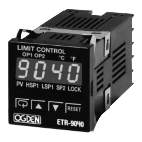
picture 1: Controller Front Panel

RF20/RF50 two tank soften valve manual
(1) 、LCD screen
1、Display station parameter status, such as: station time, reduced cycle of water per hour, water
system, the cumulative total amount of water the system, operation mode (flow model” ”, time
model” ”)
2、Controller display of Operational status
3、Display equipment failure prompted
(2)Station light: Light from top to bottom station of the station in which the display device,
which top the starting station, station device in the spool automatically switch modes to find
positive and operate.
(3)Operation button: Only in unlocking state “ ”, to the " ", " ", " " One button
" " and "+1" is used to "unlock" and with the modified parameters to use.
(4)Unlock: First press the " " & " " in the meantime, then " " appear, unlock finished
(5)Lock: Equipment without any operation after 3 minutes, shut down automatically.
(6)Mode : Unlock state, the device only in a "left softening; Right regenerate (start
position), click " " button, the time mode” ” and flow mode” " to switch between displays.
(7)Shift : Unlock state, according to “ " to go directly to the next station. Equipment
through the operation of station parameters can be set.
(8)SET : perform the operation time to complete all the stations of the parameter setting.
Ⅰ:Time mode , modify the parameters(Refer to Table 3)
Time mode, only the modified position time, including the regeneration time of about tanks, tank
cleaning time around, time around the water tank. Operation, press the " " button, the
display parameter setting interface, use button " " and " " to modify the various figures,
finished press " " button to confirm, the operation to complete.
Ⅱ: Flow mode , Modify the parameters (Refer to Table 2)
In Flow mode, the station parameters include: Regeneration time, the cycle of water, left and right
tank cleaning time. Operation, press the " " button, modify the parameters of the interface
screen display, the use of buttons " " and " " to modify the digital, finished press the "
" button to confirm.
4、Controller that the connection jack below:

RF20/RF50 two tank soften valve manual
Picture2: back of controller
(1)、Power Switch:The master switch of equipment start and stop, open the "power switch" to
work.
(2)、Power line
(3)、Brine Flow transmitter : Air plug socket (3 holes)
(4)、Soft water Flow transmitter : Air plug socket (4 holes)
(5)、Positioning: Positioning signal socket (5 pin), the valve switching control signal in place to
stop.
(6)、Start station: Start-position signal socket (5 holes), spool position control signal.
(7)、Motor: Electrical Outlet 220V, Multi-way valve switching station when the rotation.
(8)、Solenoid Valve & Motorized valve: Inlet valve outlet 220V, with power energized solenoid
valve or motorized valve open, multi-position switching valve automatically closes.
Installation
Picture3: RF20 pipe install

RF20/RF50 two tank soften valve manual
Picture 4: RF50 pipe install
Picture 5: Controller and valve connection

RF20/RF50 two tank soften valve manual
Picture 6: RF20 IN & OUT pipe install
Picture 7: RF50 IN & OUT pipe install

RF20/RF50 two tank soften valve manual
Installation for water Level Switch and Power supply system
A、Controller output directly: when it received the closed signal of high water level, controller to control
water or electric solenoid valve closed, the controller shows that "water is full” This output is + 12 v active
signal, can not access to high voltage circuit
Picture 8:directly signal from lever switch
Picture 9:lever switch
B、Single contact water level switch, the linkage of the feed water pump control
Picture 10: RF20 Single contact water level switch, the linkage of the feed water pump control
Picture11:RF50 Single contact water level switch terminal block

RF20/RF50 two tank soften valve manual
C、Conversion Relay for TWO contact water level switch, the linkage of the feed water
pump control
RF20 Recommended configuration
Model
RF20-10
RF20-15
RF20-20
RF20-25
Rated water output
10T/H
15 T/H
20 T/H
25 T/H
Rated operating pressure
0.08MPa
0.10MPa
0.12MPa
0.15MPa
Operation flow speed
15-55 m/h
the consumption of
regenerant
1:1.4 or 82g/mol
Power & power consumption
AC:220V;power consumption 0.03kw
Soften the hard residue
≤0.03mmol/L
Raw water hardness
Ⅰ:≤6mmol/L;Ⅱ:≤12mmol/L;Ⅲ:≤20mmol/L see report of raw
water);
Own use of water rate
≤5%(and the hardness of raw water)
Exchange tank
(Top&bottom4"-8UN)
(NO.×D× Effective vertical
height)
Ⅰ
2-Φ450×1368
2-Φ500×1636
2-Φ600×1636
2-Φ750×1600
Ⅱ
2-Φ450×1650
2-Φ600×1800
2-Φ600×1800
2-Φ750×1800
Ⅲ
2-Φ500×2000
2-Φ600×2200
2-Φ750×2200
2-Φ750×2200
Brine tank Capacity
350L
500L
500L
800L
The amount of resin filling
90%-95% of the tank
Distributors(4"-8UN)
40
60
80
100
Solenoid valve(Pilot type)
DF40
DF40
DF50
DF50
Inlet pipe diameter
DN40
DN40
DN50
DN50
Station
parameter
(flow
mode)
Period water
volume(Tune)
117﹡÷water
hardness
(mmol/L)
173﹡÷water
hardness
(mmol/L)
253﹡÷water
hardness
(mmol/L)
394﹡÷water
hardness
(mmol/L)
Period salt water
volume(L)
47
69
101
158
Cleaning
time(minute)*
10
12
15
20
Picture 12:Relay for two contact water level switch, the linkage of
the feed water pump control
Picture 13:two
contact

Installation, maintenance, user’s guide for RF Floating bed Control Valve
9
RF50 Recommended Configuration
Mode
RF30
RF40
RF50
Rated water output
30t/h
40t/h
50t/h
Rated operating pressure
0.16MPa
0.18MPa
0.28MPa
Operation flow speed
15-55 m/h
the consumption of regenerant
1:1.4 or 82g/mol
Power & power consumption
AC 220V;power consumption 0.03kw
Soften the hard residue
≤0.03mmol/L
Raw water hardness
Ⅰ:≤6mmol/L;Ⅱ:≤12mmol/L;Ⅲ:≤20mmol/L(see
report of raw water);
Own use of water rate
≤5%(And the hardness of raw water)
Exchange tank
(Top&bottom6"-flange)
(NO.×D× Effective
vertical height)
Ⅰ
2-Φ750×1513
2-Φ900×1587
2-Φ1000×1587
Ⅱ
2-Φ750×1800
2-Φ900×2000
2-Φ1000×2000
Ⅲ
2-Φ750×2200
2-Φ900×2300
2-Φ1000×2300
Brine tank Capacity
800L
1000L
1000L
The amount of resin filling
90%-95% of the tank
Stacked high flow water distributor
60(6"flange)
80(6"flange)
100(6"flange)
Solenoid valve(Pilot type)
DF65
DF80
DF80
Inlet pipe diameter
DN65
DN80
DN80
Station parameter(flow
mode)
Period water
volume(Tune)
375÷raw water
hardness
(mmol/L)
576÷raw water
hardness (mmol/L)
720÷raw water
hardness
(mmol/L)
Period salt water
volume(L)
150
230
288
Cleaning time(minute)*
30
40
50
Notes:
1
、
Typically, the equipment running with flow mode, but the time parameters of the model must
be based on "Installation Manual" provides the appropriate type of station set time, because
flow mode are set for regeneration under the salt volume (liters) and the regeneration mode call
time (minutes) dual control, to decrease salt content in advance to the "zero" shall prevail.
2. * 117,173,253,394,375,576,720 respectively, the corresponding exchange resin exchange
capacity cans filled to 50% (unit: mol), 50% is to consider both the exchange tank water were
recycled resin produced failure at the same time the end of the role of the different and the
protective layer, so dual-tank valve continuous production of water, frequent switching.
3. Salt water volume 47, 69, 101, 158 ware 117, 173, 253, 394 divided by 2.5 (related
calculation approximate) results.
Equipment commissioning
(1) 、Equipment, general usage should be selected flow mode, flow mode, changes in water
pressure can not affect the operation of equipment results, guaranteed yield under salt water
consumption.
(2) Time mode” ” (Safety standby mode)

Installation, maintenance, user’s guide for RF Floating bed Control Valve
10
When the water pressure is stable, the device is stable instantaneous output can choose the
time mode. Time mode, a user of the equipment time management. When the device is
malfunctioning flow mode, the " " to the time mode, does not affect the normal use of
equipment.
Operation
1、Equipment should be used more than 4 mm large particles of industrial salt. Salt in a timely
manner to ensure the salt inside the salt surface to a certain height to ensure the absorption of
salt and salt concentration in the stable.
2、Salt, open the bottom of salt under the sewage outfall, discharge of salt water tank bottom
sediment sludge.
3、Clean the filter regularly to prevent water blockage cause the device to reduce the work
pressure, the water reduction.
4、Equipment should not be frequent starts and stops, otherwise it will create chaos resin layer,
affecting water quality
5、Frequent observation equipment, in the process of transposition pressure gauge pointer is
back to "zero"
Softener maintenance
1、Inlet solenoid valve cleaning
outflow
The main valve
on cavity
inflow
spring
nut
forerunner core
Electromagnetic coils
forerunner hole
spring
seal ring
diaphragm
The main valve
cover
The main valve
body
inflow
cavity
outflow
cavity
forerunner
valve outlet
The main valve mouth
Picture14: Solenoid valve Principle

Installation, maintenance, user’s guide for RF Floating bed Control Valve
11
Picture15: pilot valve remove of the solenoid valve
2、Resin scrub
Prolonged use of equipment which, by the raw water suspended solids, turbidity, iron deposition
and other effects in the viscous resin into the surrounding pool of pollutants, resulting in
declining water quality, water pressure and reduce water production, this time the need for resin
to scrub. Scrubbing process can be divided into in vitro and in vivo scrub, to borrow equipment
for their own devices. Take the following steps are on the left and right exchange resin
Sassafras wash tank.
(1)Turn off the device inlet valve, a device to "Deputy tank water (left), the main tank cleaning
(right)";
(2)、Demolition of the left pipe and the exchange of tank water distributor
(3)、Remove from the mouth part of the exchange resin, the use of external container vitro
scrub, leaving enough of the exchange resin backwash tank expansion space upper
(4)、Ensuring the exchange of the tank is full of cases, the self-mixing device to stir resin tank;
(5)、Water distributor removed the water distribution chip, together with the left click the icon to
install the exchange pipe;
(6)、。Slightly open the inlet valve, so that the formation of sludge after mixing discharge, pay
attention to the inlet valve opening is not too large, so that was out of resin, is to be clean.
Take the same approach on the right (main) switch can scrub

Installation, maintenance, user’s guide for RF Floating bed Control Valve
12
Drainage
trench
Resin
layer
Automatic
blender
Reverse-wash expansion space
Resin
layer
Resin body wash mop(
Resin body wash mop (
Picture16: Resin scrub
3、Clean water ejector and its component
When the regeneration station do not absorb salt, do not feed water, they may be absorbing
brine injector nozzle clogging, the removal of water injector maintenance.
Picture17: Brine flow meter and electric valve system

Installation, maintenance, user’s guide for RF Floating bed Control Valve
13
Picture18: multiple valve drive schematic
Picture19: Main valve exploded view

Installation, maintenance, user’s guide for RF Floating bed Control Valve
14
Note:
1、Remove should be put on the ground or bigger clean on stage, in order to avoid ceramic pads
drop ground to break.
2、Ceramic pads polishing end toward the valve core, a magnet valve core side on the uper
valve body(starting work stations) direction
3、Install the valve core, the first guarantee positioning magnets and groove on (FIG. 26-3), the
valve core hole and let a pair of valve installed at the mouth.
4、Installation motor controller and and associated, use "manual inversion" to the start location,
perform multiple road valve and controller available calibration.
Picture 20: Position gear and drive system
Picture 21: Soft water meter demolition plan

Installation, maintenance, user’s guide for RF Floating bed Control Valve
15
Picture 22:Control principle diagram
Control valve switch procedure:
detect the
"start-position" signal
To the next station, the station is "starting
station", not detected "starting station" signal
To the next station, the station is "starting
station" and detect the "start-position" signal
Solenoid valve or
motorizedvalve on
screen is in the interface
of the station
cut off inlet,
pressure release
To the next station, the station is not a "starting station"
Detect the
"positioning"
signal motor stop
motor rotating
Delay seconds
Solenoid valve or
motorizedvalve off
The current station parameter
settings reduced to "0"
shift by hand
motor rotating motor stop
shift by hand
The current station parameter
settings reduced to "0"
Solenoid valve or
motorizedvalve off motor rotating motor stop
Solenoid valve or
motorizedvalve on
Detect the
"positioning"
signal
Delay seconds
cut off inlet,
pressure release
screen is in the interface
of the station
in flow mode
in timer mode
Picture 23:Main valve shifting procedure

Installation, maintenance, user’s guide for RF Floating bed Control Valve
16
Picture 24:RF20 Flow pressure curve
Picture 25: RF50 Flow pressure curve

Installation, maintenance, user’s guide for RF Floating bed Control Valve
17
Picture 26: RF Brine flow pressure curve

Installation, maintenance, user’s guide for RF Floating bed Control Valve
18
This manual suits for next models
6
Table of contents