Binder TWG 01 User manual

Issue 01/2011 Art. No. 7001-0034
Operating Manual
Telephone dialing device TWG 01
BINDER GmbH
Address Post office box 102
D-78502 Tuttlingen
Tel. +49 7462 2005 0
Fax +49 7462 2005 100
Internet http://www.binder-world.com
Service Hotline +49 7462 2005 555
Service Fax +49 7462 2005 93 555
Service Hotline USA +1 866 885 9794 or +1 631 224 4340
Service Hotline Spain +34 9492 677 23
Service Hotline Asia Pacific +852 39070500 or +852 39070503
Service Hotline Russia and CIS +7 495 98815 17

TWG 01 01/2011 page 2/39
Content
1. SAFETY..................................................................................................................4
1.1 Legal considerations ...........................................................................................................................4
1.2 Structure of the safety instructions......................................................................................................4
1.2.1 Signal word panel .....................................................................................................................4
1.2.2 Safety alert symbol ...................................................................................................................5
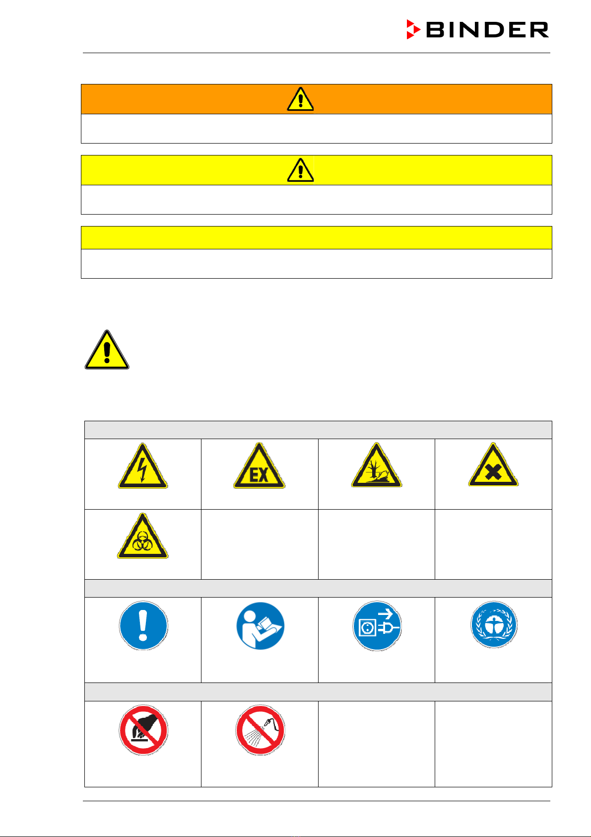
1.2.3 Pictograms................................................................................................................................5
1.2.4 Word message panel structure.................................................................................................6
1.3 General safety instructions on installing and operating the telephone dialing device TWG 01 .........6
1.4 Intended use .......................................................................................................................................7
2. UNIT DESCRIPTION..............................................................................................7
2.1 Possibilities of connection...................................................................................................................7
2.2 Call groups ..........................................................................................................................................7
2.3 Telephone numbers ............................................................................................................................7
2.4 Call confirmation .................................................................................................................................7
2.5 Alarm messages .................................................................................................................................8
2.6 Electric power supply ..........................................................................................................................8
2.7 Power failure .......................................................................................................................................8
2.8 False alarms........................................................................................................................................8
3. OPERATING ELEMENTS......................................................................................9
3.1 Connection sockets for power connection and alarm.........................................................................9
4. COMPLETENESS OF DELIVERY, TRANSPORTATION, STORAGE, AND
INSTALLATION....................................................................................................10
4.1 Unpacking, and checking equipment and completeness of delivery................................................10
4.2 Storage..............................................................................................................................................10
4.3 Location of installation and ambient conditions ................................................................................11
5. INSTALLATION AND CONNECTIONS................................................................11
5.1 Wall installation .................................................................................................................................11
5.2 Opening the unit................................................................................................................................12
5.3 Electrical connection .........................................................................................................................12
5.3.1 Operation with the power supply unit (state of delivery).........................................................12
5.3.2 Other possibilities of electrical connection..............................................................................12
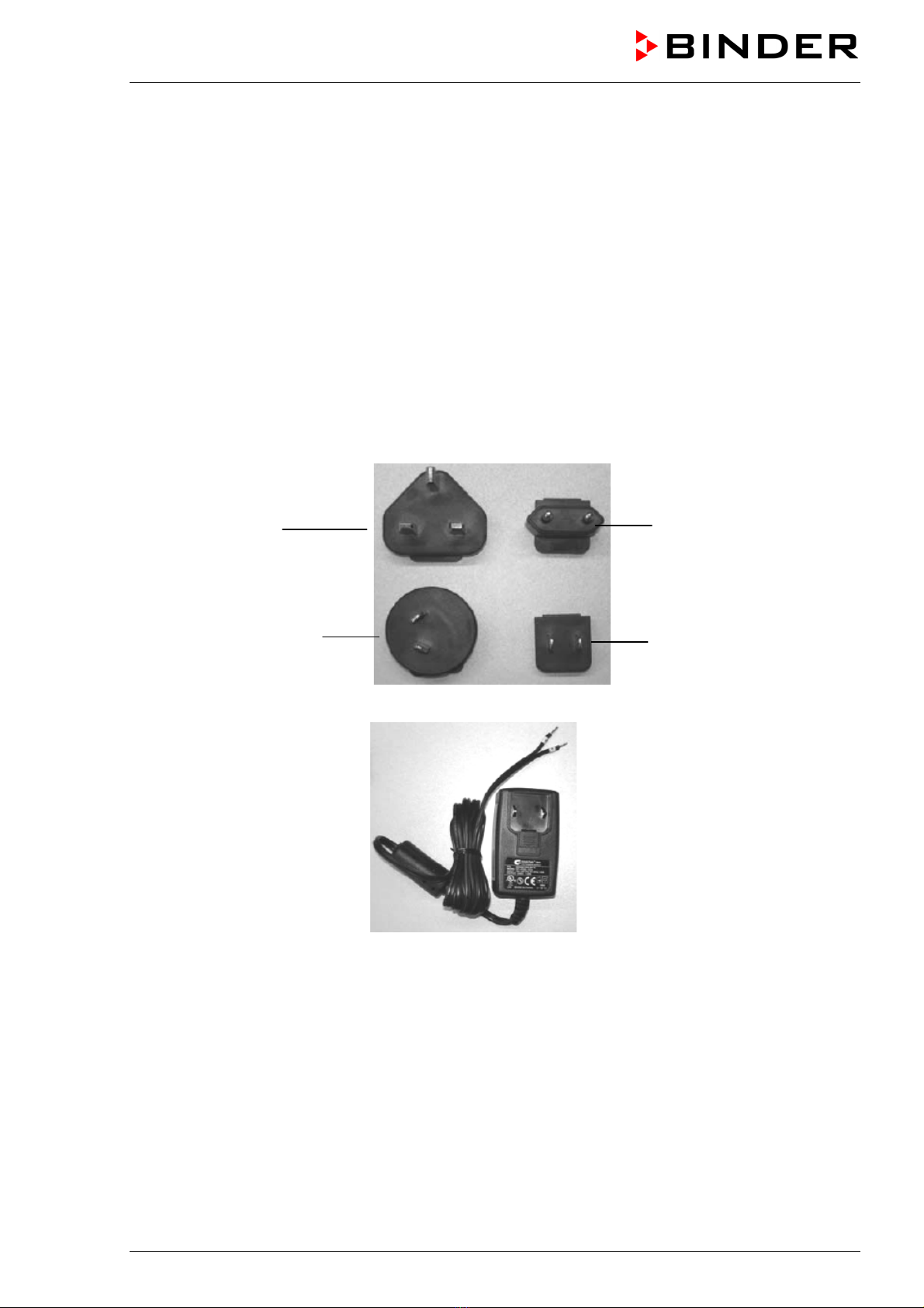
5.3.3 Putting in / changing the interchangeable plug adapters of the power supply unit ................13
5.4 Connection to the telephone line ......................................................................................................14
5.5 Keyboard...........................................................................................................................................15
5.5.1 Function of LED symbols........................................................................................................15
5.5.2 Overview command keys........................................................................................................16
6. PROGRAMMING..................................................................................................16
6.1 General information...........................................................................................................................16
6.1.1 Situation following connection (chap. 5).................................................................................16
6.1.2 Basic entry principle................................................................................................................17
6.2 Selection of the connection type for the Alarm Box AB 01 and setting the alarm delay time...........17
6.3 Recording of voice message.............................................................................................................18
6.4 Entry of telephone numbers..............................................................................................................20
6.4.1 Standard entry ........................................................................................................................20
6.4.2 Special case: Occupied and impossibility to distinctly recognize the dialing tone .................21
6.4.3 Calling a mobile phone or using a provider prefix ..................................................................21
6.4.4 Entry of a pager message.......................................................................................................22
6.4.5 Entry in case of a personal branch extension with local loop.................................................23
6.4.6 Number of call repeats............................................................................................................24

TWG 01 01/2011 page 3/39
6.4.7 Length of playback time..........................................................................................................25
6.4.8 Test call...................................................................................................................................25
6.5 Defining the call groups ....................................................................................................................26
6.6 Call confirmation ...............................................................................................................................27
6.6.1 Setting the confirmation code .................................................................................................27
6.6.2 Defining the number of received confirmation codes .............................................................27
6.7 Limitation of the alerting....................................................................................................................28
6.8 Password protection of programming ...............................................................................................29
7. CONNECTION TO THE ALARM SYSTEM..........................................................30
7.1 Connection to the alarm box AB 01 ..................................................................................................30
7.2 Connecting further alarm contacts with 3 zone operation ................................................................31
7.3 APT-COM™ 2.01 settings for remote alarm.....................................................................................32
7.4 APT-COM™ 3 settings for remote alarm..........................................................................................33
8. OPERATION.........................................................................................................33
8.1 State of alert......................................................................................................................................33
8.2 Stopping / resetting an alarm ............................................................................................................33
8.3 Manual alarm / Test alarm ................................................................................................................33
9. TROUBLESHOOTING .........................................................................................34
9.1 Table to define errors and offering solutions ....................................................................................34
9.2 Reset of programming ......................................................................................................................35
10. CLEANING, AND SERVICE.................................................................................35
10.1 Cleaning ............................................................................................................................................35
10.2 Service ..............................................................................................................................................36
11. DISPOSAL............................................................................................................36
11.1 Disposal of the transport packing .....................................................................................................36
11.2 Decommissioning..............................................................................................................................36
11.3 Disposal of the unit in the Federal Republic of Germany .................................................................37
11.4 Disposal of the unit in the member states of the EC except for the Federal Republic of Germany .38
11.5 Disposal of the unit in non-member states of the EC .......................................................................39
12. TECHNICAL DATA ..............................................................................................39

TWG 01 01/2011 page 4/39
Dear customer,
For the correct operation of the telephone dialing device TWG 01, it is important that you read this
operating manual completely and carefully and observe all instructions as indicated. Failure to read,
understand and follow the instructions may result in personal injury. It can also lead to damage to the unit
and/or poor equipment performance
1. Safety
This operating manual is part of the components of delivery. Always keep it handy for reference.
To avoid injuries and damage observe the safety instructions of the operating manual.
WARNING
Failure to observe the safety instructions.
Serious injuries and unit damage.
¾Observe the safety instructions in this operating manual
¾Carefully read the complete operating instructions of the telephone dialing device TWG
01.
1.1 Legal considerations
This operating manual is for informational purposes only. It contains information for installing, start-up,
operation and maintenance of the product. Note: the contents and the product described are subject to
change without notice.
Understanding and observing the instructions in this operating manual are prerequisites for hazard-free
use and safety during operation and maintenance. In no event shall BINDER be held liable for any
damages, direct or incidental arising out of or related to the use of this manual.
This operating manual cannot cover all conceivable applications. If you would like additional information,
or if special problems arise that are not sufficiently addressed in this manual, please ask your dealer or
contact us directly by phone at the number located on page one of this manual
Furthermore, we emphasize that the contents of this operating manual are not part of an earlier or
existing agreement, description, or legal relationship, nor do they modify such a relationship. All
obligations on the part of BINDER derive from the respective purchase contract, which also contains the
entire and exclusively valid statement of warranty administration. The statements in this manual neither
augment nor restrict the contractual warranty provisions.
1.2 Structure of the safety instructions
In this operating manual, the following safety definitions and symbols indicate dangerous situations
following the harmonization of ISO 3864-2 and ANSI Z535.6.
1.2.1 Signal word panel
Depending on the probability of serious consequences, potential dangers are identified with a signal
word, the corresponding safety color, and if appropriate, the safety alert symbol.
DANGER
Indicates an imminently hazardous situation that, if not avoided, will result in death or serious
(irreversible) injury.

TWG 01 01/2011 page 5/39
WARNING
Indicates a potentially hazardous situation which, if not avoided, could result in death or serious
(irreversible) injury
CAUTION
Indicates a potentially hazardous situation which, if not avoided, may result in moderate or minor
(reversible) injury
CAUTION
Indicates a potentially hazardous situation which, if not avoided, may result in damage to the product
and/or its functions or of a property in its ambiance.
1.2.2 Safety alert symbol
Use of the safety alert symbol indicates risk of injury.
Observe all measures that are marked with the safety alert symbol in order to avoid death or
injury.
1.2.3 Pictograms
Warning signs
Electrical hazard
Explosive atmosphere
Pollution Hazard
Harmful substances
Biohazard
Mandatory action signs
Mandatory regulation
Read operating
instructions
Disconnect the power
plug
Environment protection
Prohibition signs
Do NOT touch
Do NOT spray with
water

TWG 01 01/2011 page 6/39
Information to be observed in order to ensure optimum function of the product.
1.2.4 Word message panel structure
Type / cause of hazard.
Possible consequences.
∅Instruction how to avoid the hazard: prohibition.
¾Instruction how to avoid the hazard: mandatory action.
Observe all other notes and information not necessarily emphasized in the same way, in order to avoid
disruptions that could result in direct or indirect injury or property damage.
1.3 General safety instructions on installing and operating the telephone
dialing device TWG 01
With regard to operating the telephone dialing device TWG 01and to the installation location, please
observe the guideline BGI/GUV-I on safe working in laboratories (formerly BGR/GUV-R 120 or ZH 1/119
laboratory guidelines issued by the employers’ liability insurance association) (for Germany).
BINDER GmbH is only responsible for the safety features of the unit provided skilled electricians or
qualified personnel authorized by BINDER perform all maintenance and repair, and if components
relating to chamber safety are replaced in the event of failure with original spare parts.
CAUTION
Danger of overheating.
Damage to the unit.
∅Do NOT install the unit in unventilated recesses.
¾Ensure sufficient ventilation for dispersal of the heat.
Do not operate the telephone dialing device TWG in hazardous locations.
DANGER
Explosion hazard.
Danger of death.
∅Do NOT operate the unit in potentially explosive areas.
¾KEEP explosive dust or air-solvent mixtures AWAY from the unit.
DANGER
Electrical hazard.
Danger of death.
∅The unit must NOT become wet during operation or maintenance.
The telephone dialing device TWG 01 was produced in accordance with VDE regulations and was
routinely tested in accordance to VDE 0411-1 (IEC 61010-1).

TWG 01 01/2011 page 7/39
1.4 Intended use
The telephone dialing device TWG 01 serves to transmit an alarm message to one or several recipients
via the telephone line. The unit receives the alarm from the Alarm Box AB 01 from BINDER and transmits
the recorded messages to the programmed telephone numbers. For test purposes or emergency it is
possible to release an alarm directly by pressing a key.
An alarm can also be triggered directly via the zero-voltage relay alarm contacts of some BINDER
temperature chambers.
Following the instructions in this operating manual is part of the intended use.
2. Unit description
The telephone dialing device TWG 01 serves to transmit an alarm message triggered by the
communication software APT-COM™ from BINDER to one or several recipients via the telephone line.
The unit receives the alarm from the Alarm Box AB 01 from BINDER and transmits the recorded
messages to the programmed telephone numbers. For test purposes or emergency it is possible to
release an alarm directly by pressing a key.
In addition to the Alarm Box AB 01 an alarm can also be triggered directly via the zero-voltage relay
alarm contacts of some BINDER temperature chambers. With 3 zone operation, up to 3 different alarm
contacts can trigger alarms causing the TWG 01 to dial different phone number combinations (call
groups) and to transmit combination of messages which have been defined accordingly.
2.1 Possibilities of connection
The TWG 01 is connected at the output side to a public telephone network directly or via substation of a
private telephone installation. On the input side, the transmission of the alarm occurs via a zero-voltage
relay alarm contact of the Alarm Box AB 01. With 3 zone operation you can connect up to 3 different
alarm contacts. For the connection to the telephone network you need a TAE-N socket (N means non-
telephone unit, e.g. telephone responders or facsimile).
2.2 Call groups
You can define up to 4 phone number combinations (call groups) (chap. 6.5). For each of these call
groups you can assign a combination of messages and have dialed up to 6 of the entered phone
numbers (chap. 6.3).
2.3 Telephone numbers
The TWG 01 provides an automatic dialing service that, according to programming, can contact up to six
different telephone numbers in line. Each telephone number can consist of up to 32 digits. In case of an
alarm each phone number can be called up to 15 times. For each call group up to 6 of the entered phone
numbers can be dialed. If a dialed line is busy, the redial mode is activated.
2.4 Call confirmation
the recipient can confirm the call by dialing a code number (chap. 6.6). After a defined number of
received confirmation, the alarming ends.

TWG 01 01/2011 page 8/39
2.5 Alarm messages
Enter an individual alarm text by means of the voice recording facility. You can record up to 4 messages.
The maximum length of all alarm messages is 32 seconds. In case of an alarm the TWG 01 will send the
selected messages during the selected interval of 50, 70, 90 or 110 sec. If the recorded message is
shorter it will be repeated accordingly. For each call group there is a special combination of messages
(chap. 6.3).
2.6 Electric power supply
For the electric power supply the TWG 01 requires 12 V DC/100 mA max. taken from the delivered
stabilized power supply unit. Do not use any different connection or power supply unit because this could
damage the TWG 01.
Do NOT use the TWG 01 outdoor, in humid locations or in explosive areas. This is not permitted and can
lead to faults and to damage, including the connected devices.
2.7 Power failure
All settings, recorded messages and entered phone numbers remain stored in case of power failure. To
ensure alarm transmission during a power failure we recommend taking the electric power supply from a
central alarm facility with a power supply buffered by a 12V accumulator which is permanently loaded by
a charger suitable for permanent loading.
To enable alarming during a power failure, the APT-COM™ computer, if appropriate the monitoring
computer (Watch Tool), and the Alarm Box AB 01 must be connected to an interruption free power supply
(e.g. battery buffer for PCs).
All phone numbers, messages and programming are conserved in a fix memory even in case
of a power failure.
2.8 False alarms
Never program telephone numbers of the police or the fire service. This is not permitted.
Please consider that you will have to pay for calling the police when it has provoked alarms.
By mistake the manual alarm-key could release an alarm. You can protect yourself against
such a false alarm by installing the unit as inaccessibly as possible.

TWG 01 01/2011 page 9/39
3. Operating elements
Microphone
Line socket for phone connection
Sockets for power connection and alarm
Control LEDs
Keyboard
Figure 1: Operating elements
3.1 Connection sockets for power connection and alarm
12 V DC Alarm zone
Figure 2: Connection sockets on the top of the unit
Entry of power supply 12 V DC / 100 mA. For power supply connection see chap. 5.3.
Logic of alarm input 1: closed= N.C. (normally closed), logic of the Alarm Box AB 01
Connecting the Alarm Box AB 01 (and, if appropriate, further alarm contacts with 3 zone operation) will
take place after programming. See chap. 7.
Proceed in the order of this manual: First install the TWG 01 and connect it to the power
supply and the telephone line (chap. 5). Then programming will be done 6), and only
thereafter the Alarm Box AB 01 will be connected (chap. 7).

TWG 01 01/2011 page 10/39
4. Completeness of delivery, transportation, storage, and
installation
4.1 Unpacking, and checking equipment and completeness of delivery
After unpacking, please check the unit and its optional accessories, if any, based on the delivery note for
completeness and for transportation damage. Inform the carrier or post office/parcel service immediately
if transportation damage has occurred.
Scope of delivery:
•Telephone dialing device TWG 01
•Connection cable 2 m / 6.6 ft (connection to telephone wall jack)
•Operating Manual Telephone dialing device TWG 01
•Power supply unit with various interchangeable plug adapters
Plug adapter for UK
Plug adapter for Australia
Plug adapter for EU
Plug adapter for the USA
Figure 3: Delivered interchangeable plug adapters
Figure 4: Power supply unit 90-264V AC / 12V DC (Art. No. 5020-0029)
For disposal of the transport packing, see chap. 11.1.
4.2 Storage
Intermediate storage of the unit is possible in a closed and dry room. Observe the guidelines for
temporary decommissioning (chap. 11.2).
•Permissible ambient temperature range: 0 °C / 32 °F up to +40 °C / 104 °F.
•Permissible ambient humidity: max. 80 % r.H., non-condensing
When after storage in a cold location you transfer the unit to its warmer installation site, condensation
may form. Before start-up, wait at least one hour until the unit has attained ambient temperature and is
completely dry.

TWG 01 01/2011 page 11/39
4.3 Location of installation and ambient conditions
Select a convenient place for the telephone dialing device TWG 01.
The place of the installation should be:
•close to the APT-COM™ computer or the monitoring computer (Watch Tool) and to the Alarm Box
AB 01
•close to a telephone wall jack (2 m / 6.6 ft connection cable enclosed)
•rather concealed or inaccessible
•a dry location
•Permissible ambient temperature range: 0 °C / 32 °F up to +40 °C / 104 °F.
•Permissible ambient humidity: 80 % r.H. max., non-condensing.
Note that unauthorized persons may switch off the device or the audible alarm signal. We
recommend installation e.g., inside a distribution box.
To completely separate the unit from the power supply, you must disconnect the power plug. Install the
unit in a way that the power plug is easily accessible and can be easily pulled in case of danger.
Do not install or operate the unit in hazardous locations.
DANGER
Explosion hazard.
Danger of death.
∅Do NOT operate the unit in potentially explosive areas.
¾KEEP explosive dust or air-solvent mixtures AWAY from the vicinity of the unit.
5. Installation and connections
5.1 Wall installation
Choose a convenient place for the dialing unit TWG 01.
The place of the installation should be:
•close to the APT-COM™ PC or the monitoring computer (Watch Tool) and to
the Alarm Box AB 01
•close to a telephone wall jack (2 m connection cable enclosed)
•concealed or inaccessible
Fasten the two delivered dowels and screws at a distance of 50 mm / 1.97 in and
mount the TWG 01.
Note that unauthorized persons could release an alarm or reset the programming
unintentionally. We recommend installing the TWG 01 inside a distribution box or similar.

TWG 01 01/2011 page 12/39
5.2 Opening the unit
Push the covering of the connection upwards. Underneath there are the
connection sockets for the power supply and alarm (connection to the Alarm Box
AB 01).
5.3 Electrical connection
5.3.1 Operation with the power supply unit (state of delivery)
The power supply unit is delivered ready-mounted to
the TWG 01.
Connection of the power supply unit at the TWG 01:
•Clamp 12V DC+ connected to the line marked +
•Clamp 12V DC - connected to the line marked -
Figure 5: Connecting the power supply unit
5.3.2 Other possibilities of electrical connection
12 V DC alarm zone
The TWG 01 must be connected to a 12 V DC-voltage. There are three connection possibilities:
1. Connection to the 12 V DC-supply of a central alarm system, if installed.
2. Connection to the delivered 12V power unit (state of delivery)
3. Connection to an accumulator with 12 V and at least 1.2 Ah. The accumulator must be suitable for
permanent loading by an interruption-free power supply.
•Rated voltage TWG 01: 7,7 to 13,8 V DC
•Quiescent current: max. 25 mA (at 12 V DC)
•Rated current (alarm): max. 100 mA (at 12 V DC)
•When connecting, please observe the regulations specified by the local electricity supply company as
well as the VDE directives (for Germany)
CAUTION
Danger of incorrect rated voltage.
Damage to the TWG 01.
¾Check the power supply voltage before connection and start-up.

TWG 01 01/2011 page 13/39
We recommend taking the electric power from a central alarm facility (as far as existing) with a backed-up
power feeding 230V AC (e.g. battery buffer for PCs). Only then the alarm transmission during a power
failure is guaranteed. The same is true when using the delivered 12V power supply unit.
The max. power consumption of the TWG 01 is 1.2 Watt. Additionally for alarming during a power failure,
it is necessary that the computer on which APT-COM™ 2.0 or the Watch Tool software is running is also
connected to a backed-up power feeding (e.g. battery buffer for PCs).
DANGER
Incorrect power supply voltage when connecting the power supply unit.
Electrical hazard.
Danger of death.
Damage to the power supply unit.
¾Check the power supply voltage before connection and start-up.
To completely separate the unit from the power supply, you must disconnect the power plug.
Install the unit in a way that the power plug is easily accessible and can be easily pulled in
case of danger.
5.3.3 Putting in / changing the interchangeable plug adapters of the power supply unit
The delivered power supply unit covers a power supply tension range from 90V AC up to 264V AC and
provides 4 interchangeable plug adapters for Europe, UK, Australia, and the USA. It is thus suitable for all
tensions between 90V and 264V AC 50/60Hz worldwide.
The interchangeable plug adapters accompany the unit and can be used as required.
To put in or change the interchangeable plug adapters proceed as described following:
Figure 6: TWG 01 and power
supply unit in state of delivery.

TWG 01 01/2011 page 14/39
Figure 7: Removing the wildcard
for interchangeable plug adapters
-
Figure 8: Putting in the desired
plug adapter
5.4 Connection to the telephone line
Use the delivered cable to establish the connection with the telephone line via the
Line socket on the top of the unit.
Insert the RJ connector (Western plug) into the Line socket of the unit until it snaps
in. The TAE-N-plug has to be put in to the N-coded socket of the TAE socket (N =
non-telephone) of a telephone responder, a fax-device, or a modem.
For use abroad, telephone pick-ups are available in commerce.
If the cable is to be directly connected to a wall box (without plug), cut off the TAE-N plug and cramp the
wires as follows:
Connection to the telephone (wall socket):
Plug to TWG 01 (wires 3 and 4 are not needed)
pin 1 (generally yellow)
pin 2 (generally green)
Front view
1 2 3 4
1
2

TWG 01 01/2011 page 15/39
5.5 Keyboard
Figure 9: Keyboard of TWG 01
5.5.1 Function of LED symbols
LED Off Lit Flashing
green
No connection to the
phone line, or
connection to phone
line exists, but is
inactive (no local loop,
this may be introduced
only when dialing) *
Connection to the phone line
OK
TWG 01 dialing (alarm)
yellow
State of alert
(standby)
Message recording or
playback
Flashing once or twice during
programming, or lit during 1,5 sec:
confirmation of entry
Flashing 3 or 4 times during
programming:
entry mistake
Flashing continuously: uncompleted
programming of the message and/or
phone number
red
No connection to power
supply
Connection to power supply
OK
Alarm
Flashing continuously even after
pressing button : see chap. 9
* This depends on the type of telephone connection and on the local and national configuration of the
telephone network.

TWG 01 01/2011 page 16/39
5.5.2 Overview command keys
Key Function
to Program selection, Information entry during programming (chap. 6.1.2)
Program selection for limiting the number of effective alerts (chap. 6.7)
Program selection for recording a voice message (chap. 6.3)
Starting and ending number entry for pagers (chap. 6.4.4)
Starting number entry for number of call repeats (chap. 6.4.6)
Entering the number of effective alerts (chap. 6.7)
Direct manual alarm (in emergency cases or for test purpose) (chap. 8.3)
Playback independent of dialing tone (chap. 6.4.2)
Call group (chap. 6.5, 6.6.2)
Reset of programming (chap. 9.2)
Programming
Dialing delay (chap. 6.4.3)
Program selection for number of call repeats (chap. 6.4.6)
Transfer delay for pagers (chap. 6.4.4)
Programming reset (chap. 9.2)
Entering the number of confirmation codes for all call groups (chap. 6.6.2)
Stopping / resetting an alarm (chap. 8.2)
Alarm memory deletion
Voice message recording or playback stop (chap. 6.3)
Test mode stop
6. Programming
In this chapter all kinds of programming are described that you need to execute until your TWG 01 is
ready for operation.
6.1 General information
6.1.1 Situation following connection (chap. 5)
•Red LED lit: Power supply is on
•Yellow LED flashes: Messages are programmed incompletely so far
•Green LED lit: Connection to phone line ok
or
•Green LED not lit: Connection to phone line exists, but is inactive (no local loop, this may be
introduced only when dialing). This depends on the type of telephone connection and on the local and
national configuration of the telephone network.

TWG 01 01/2011 page 17/39
6.1.2 Basic entry principle
Hitting a key, termination of a program step and of the whole entry are confirmed by the yellow LED. Most
of the program entries require that the program key is used three times during the procedure:
Step Key Effect Yellow LED
1. Program call 1x flashing
2. Entry via keyboard Program selection 1x flashing
following each hit
3.
Selection of program step
confirmed 2x flashing
4. Entry via keyboard or voice
recording Information entry 1x flashing
following each hit
5. Programming terminated lights up for 1.5 sec
Wait for the yellow LED lighting up before pressing the next key. Pressing the next key too
quickly may lead to errors. Mind that every programming is confirmed at the end by the
yellow LED lighting up for 1.5 seconds.
If you do not press any key for 10 seconds during programming, the entry will be cancelled. The yellow
LED flashes 4 times, the previous entries will not be adopted.
Avoid pausing during entry. After 10 seconds you will need to start again.
You can cancel a started programming with button .
If the red LED flashes continuously (alarm), press button and continue with the programming.
6.2 Selection of the connection type for the Alarm Box AB 01 and setting the
alarm delay time
The TWG 01 can react to impulses of alarm systems which are either set to “Normally open“ (N.O.) or to
“Normally closed“ (N.C.). It can be connected to alarm systems of both types. To connect it to the
BINDER Alarm Box AB 01 the type of alarm must be set to “Normally closed”.
Connection types for the alarm system:
Normally open (not used) Normally closed
For the direct connection to a zero-voltage relay alarm contact at a BINDER temperature chamber the
logic of this alarm contact can be accordingly set at the TWG 01.
The delay time for triggering an alarm can be defined. Different settings are available for the different
activation types. Settings and are suitable for impulse-type activation as with sensors of magnetic
contact, shocks, or breaking. Settings or are suitable for continuous activation by the BINDER
Alarm Box AB 01 and serve to avoid faulty alarms. If the alarm by the Alarm Box AB 01 ends before
rundown of the selected alarm delay time (10 or 15 sec), the dialing procedure at the TWG 01 is stopped.
The TWG 01 is still on alert noticeable by the red LED lit.

TWG 01 01/2011 page 18/39
Delay time:
for impulse-type activation (not used) for continuous activation by AB 01
(0.06 sec delay)
(0.2 sec delay)
(10 sec delay)
(15 sec delay)
To set the connection type and the alarm delay time proceed as follows:
Step Key Effect Yellow LED
1. Program call 1x flashing
2.
Program selection:
“Entry of alarm type“ 1x flashing
3. Selection of program step confirmed 2x flashing
4.
Information entry about connection
type: “Normally closed“ 1x flashing
5. or
Information entry about alarm delay
time 1x flashing
6. Programming terminated lights up for 1.5 sec
6.3 Recording of voice message
The maximum total duration of the alarm messages transmitted by the TWG 01 via telephone is 32 sec. If
you want to record a shorter message, you can terminate recording with the key. You can divide the
32 seconds to up to 4 individual messages.
During recording keep close to the built-in microphone.
Step Key Effect Yellow LED
1. Program call 1x flashing
2.
Program selection:
“Voice recording “ 1x flashing
3. Selection of program step confirmed lights up for 1.5 sec
4. e.g. Selection (0, 1, 2, or 3) of a message
with 3 zone operation 1x flashing
5. Selection of program step confirmed lit
6. Voice entry Entry of voice message via microphone lit
32 sec after start of
recording
7.
or
End of voice recording off

TWG 01 01/2011 page 19/39
Use the keys up to to select the message, which shall be recorded. You can enter up to 4
messages with a total length of 32 seconds maximum. These messages are one general information
message (selection “0”) and up to three specific information messages (selection “1”, “2” or “3”). The 4
messages must be recorded in this order.
General information
Specific information 1
Specific information 2
Specific information 3
When connecting a call group (chap. 6.5) these messages will be transmitted in the following
combination:
Call group Transmitted messages
Test call or manual alarm (button ) General information + Specific information 1
Call group 1 General information + Specific information 1
Call group 2 General information + Specific information 2
Call group 3 General information + Specific information 3
To check the voice message for control purpose, proceed as follows:
Step Key Effect Yellow LED
1. Program call 1x flashing
2.
Program selection:
“Voice message playback “ 1x flashing
3. Selection of program step confirmed 2x flashing
4. e.g. Selection (0, 1, 2, or 3) of a message
with 3 zone operation 1x flashing
5. Selection of program step confirmed lit
Playback of voice message
6. yellow LED lit lit
End of playback
32 sec after playback
start
7.
or
yellow LED off off

TWG 01 01/2011 page 20/39
6.4 Entry of telephone numbers
You can save up to six phone numbers at the TWG 01. Each phone number as assigned a storage
locations, i.e., a number between 1 and 6. The first phone number is assigned location No. 1 and so on.
Noting down the storage location number is useful if you want to change a phone number later.
Each phone number can be up to 32 digits long.
Never enter a telephone number of the police here. According to the emergency call-security
directions of the police this is not permitted. In order to guarantee a frictionless course of an
alarm you should discuss with the to be called persons which measures they should take
when they receive an alarm call of APT-COM™.
It is useful to note the telephone numbers with their corresponding saving location for
possible later modifications.
6.4.1 Standard entry
This type of entry is the appropriate one if you hear the dialing tone when picking up the phone and if you
do not intend to call a pager or cellular (mobile) phone.
Step Key Effect Yellow LED
1. Program call 1x flashing
2. Program selection: “Entry of a phone
number to be dialed“ 1x flashing
3. e.g. Selection of the of the phone number
saving location (1 to 6) 1x flashing
4. Selection of program step confirmed 2x flashing
5. Entry of phone
number
Information entry: phone number of the
selected location (32 digits max.)
1x flashing
following each hit
6. Programming terminated lights up for 1.5 sec
To modify the phone umber repeat the entry with the new number.
Each phone number can be entered only once, i.e. on a single saving location.
Having dialed the phone number, the TWG 01 tries for 7 sec to recognize the tone signal (call accepted,
occupied, not recognized).
•Call accepted →message playback
•Occupied →dialing repeated after 30 sec.
•Not recognized →dialing the next number
Table of contents