Bio Medic Data Systems DAS-8010 User manual
Bio Medic Data Systems
www.BMDS.com 1-800-526-BMDS or 302-628-4100 for Support Questions
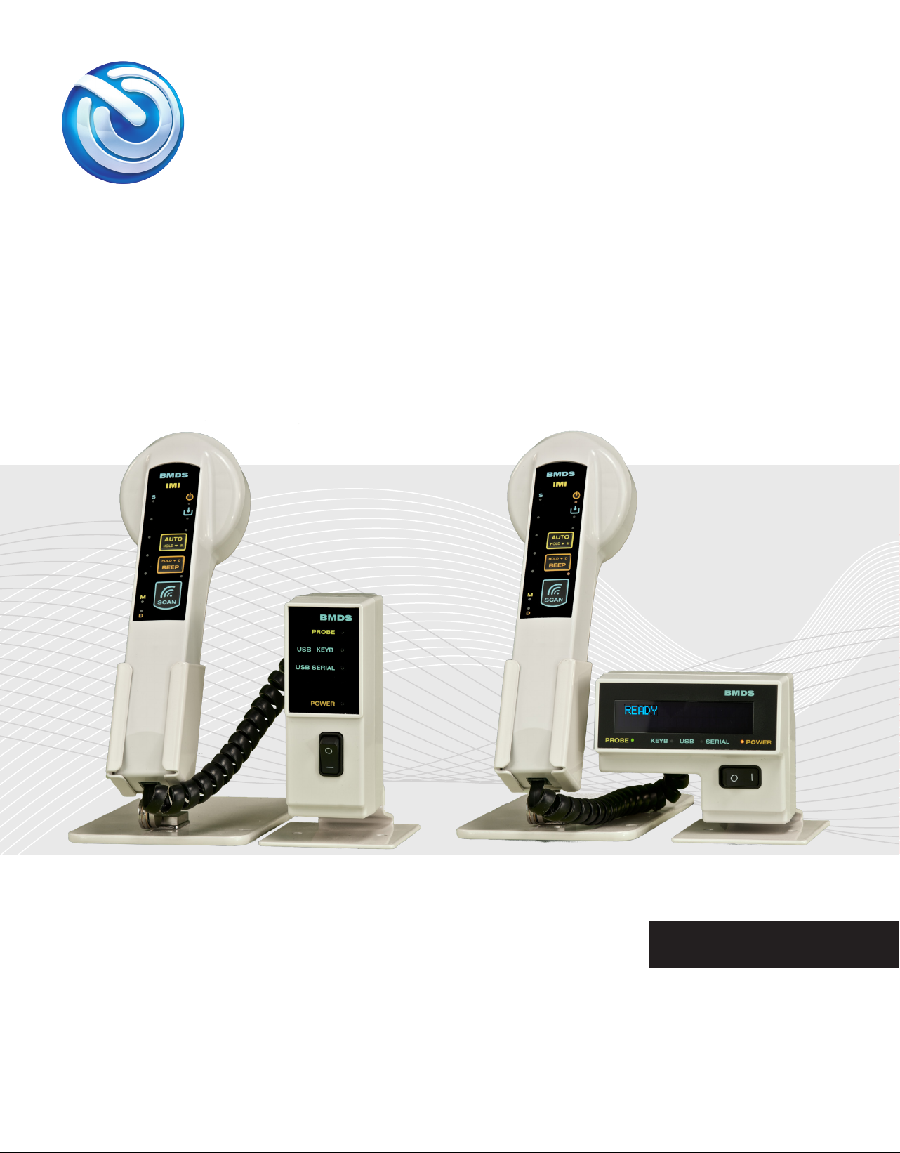
DAS-8010/20 WITH RSP-8004
User Manual
English v.1

www.BMDS.com 1-800-526-BMDS or 302-628-4100 for Support Questions
INTRODUCTION
Copyright
Warranty
Congratulations on your purchase of the DAS-8010 or DAS-8020 Wired Reader System! The DAS-8010
and DAS-8020 are our newest generation of console reader technology. The systems are the best, simplest
solution for connecting our implantable animal transponders to a computer system. The system reference
for this manual is designed to be used in conjunction with our new RSP-8004 for IMI-500 and IMI-1000
read-only transponders. The primary role of the DAS unit is a system interface for the RSP probes with a
computer.
The rmware described in this manual is copyrighted, with all rights reserved by Bio Medic Data Systems.
Under the United States copyright laws, the rmware described in the manual may not be copied,
photocopied, or otherwise reproduced, in whole or in part, without the prior written consent of Bio Medic
Data Systems. Any permitted copies must include the same proprietary and copyright notices as were
afxed to the original. Under these laws, copying includes translating to another language or format.
BMDS warrants our reader product to be free of defects in material and workmanship, under regular use
and service for 90 days from the date of delivery to the original purchaser. This is the sole warranty and
under no circumstances do we assume responsibility for consequential or incidental damages resulting
from the sale, use, handling, or installation of equipment.
2
All attempts have been made to provide you with a manual as comprehensive and factual as possible.
However, we reserve the right to make changes at any time and without notice in prices, colors,
material, equipment, specications, models, and availability. Some of the information in the manual
may have been updated since the time of publication; please check with BMDS for complete details of
any updates.
RSP Stand DAS-Host
Optional with the RSP-8004 Optional companion software.
Host
DAS
USB Data Cable
www.BMDS.com 1-800-526-BMDS or 302-628-4100 for Support Questions
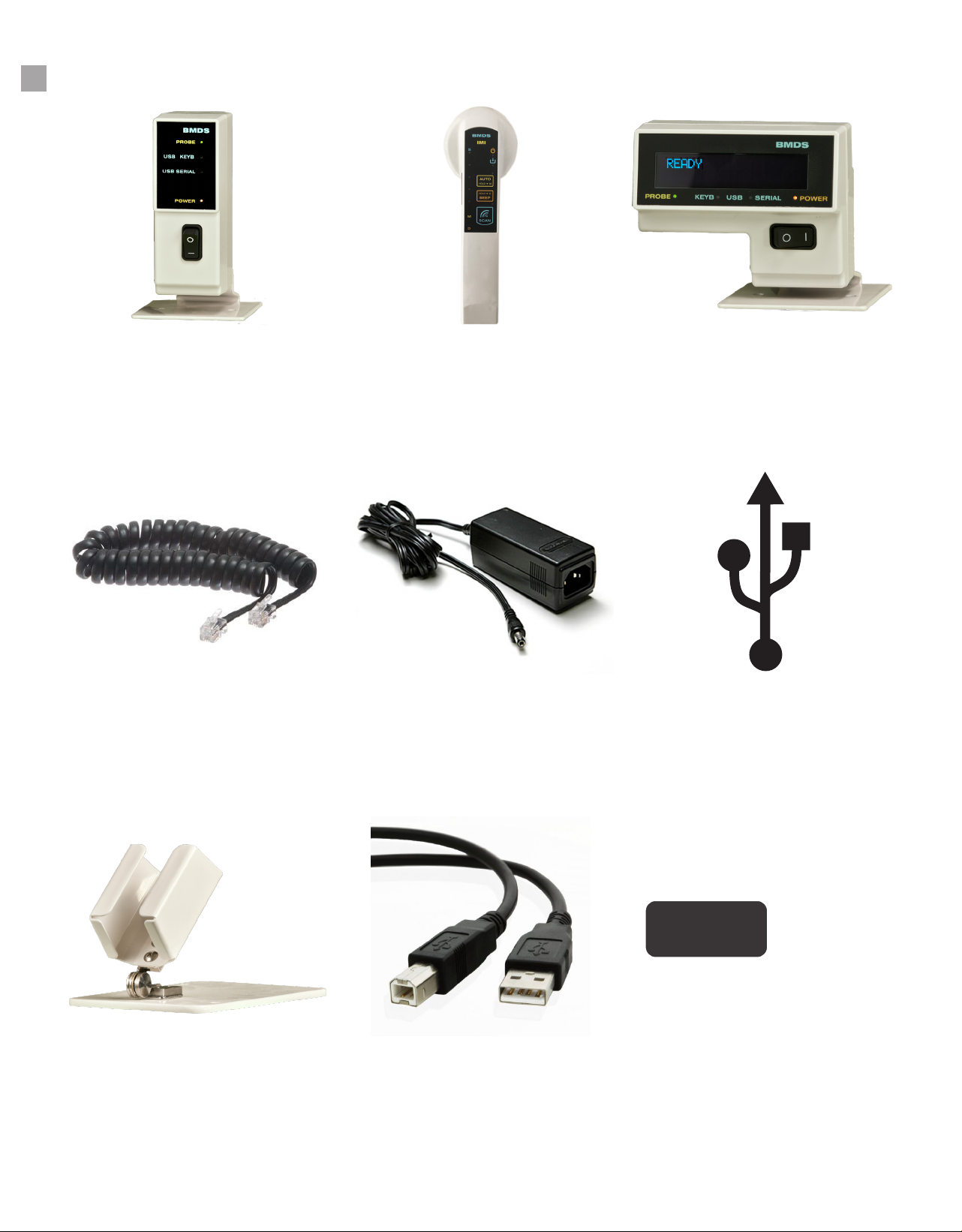
DAS-8010/20 WITH RSP-8004 CHECK LIST
DAS-8010 Unit
RJ-11 Coil Cable
RSP-8004
DC12V Power Supply
DAS-8020
BMDS Proprietary USB
Driver
3

www.BMDS.com 1-800-526-BMDS or 302-628-4100 for Support Questions
CONTENTS
1.
2.
Buttons and Features ................................................................................................. 6
System Overview......................................................................................................... 7
System Setup ............................................................................................................. 8
System Communication Options ................................................................................ 9
Using DAS-8010/8020 with RSP-8004...................................................................... 10
RSP-8004 Keypad and Display ................................................................................. 11
RSP-8004 Reading Micro-Transponders ............................................................ 12-13
Connecting to DAS-Host 8000 ............................................................................ 14-15
Using Das-Host with RSP-8004 .......................................................................... 16-17
Mapping with RSP-8004 ...................................................................................... 17-18
System Overview
Functions & Usage
4

www.BMDS.com 1-800-526-BMDS or 302-628-4100 for Support Questions
QUICK START GUIDE
5
To get started, please follow these easy steps.
Connecting to a Computer
The DAS-8010 and DAS-8020 can be connected to a computer by either the USB ports or the 9-pin RS-
232 serial connection for legacy PC system support. There are two USB options to select. You can either
use the Serial USB (driver installation required) or Keyboard USB. Simply connect the reader to the
computer using the appropriate cable and turn on the power on the unit to activate the connected smart
probe. The RSP-8004 smart probe referenced in this manual is used to detect the IMI-500 and IMI-1000
transponders only. The smart probe is connected to the system via the supplied proprietary probe cable.
The easiest communication with the computer is by simple Keyboard USB requiring no software driver.
Keyboard USB can be used with Windows OS, Mac OS, Android or Linux. For simple data transfer, simply
connect by Keyboard USB, open the application and transmit data. Data scanned will populate data elds
in any active program window.
If the data collection software requires a dedicated secure connection, use the Serial USB or RS-232 port
for communication. When connecting by Serial USB, a software driver will be needed. Windows OS only
drivers are supplied with the reader (NOTE: Windows 10 provides native driver support and no additional
drivers are required). No drivers are required to connect by the RS-232 Serial Com Port.
Step by Step Procedures for Connecting
1. Start by connecting the power supply to the reader unit
2. Connect RSP-8004 smart probe to the reader by the RJ-11 coil cable
3. Connect the USB cable or RS-232 Serial cable to the computer
4. Turn power on to the unit. Power LED should turn from Red (OFF) to Orange (ON). The Probe LED
and appropriate USB connection should also be lit. Note there is no LED for the RS-232 Serial cable
on the DAS-8010 reader but there is one on the DAS-8020 reader
5. Press scan on the smart probe to energize the transponder and transmit information to the connect-
ed computer. If using connection other than Keyboard USB, additional setup including installation of
DASHost 8000 or conguring data collection software will be required.
Power Button
www.BMDS.com 1-800-526-BMDS or 302-628-4100 for Support Questions
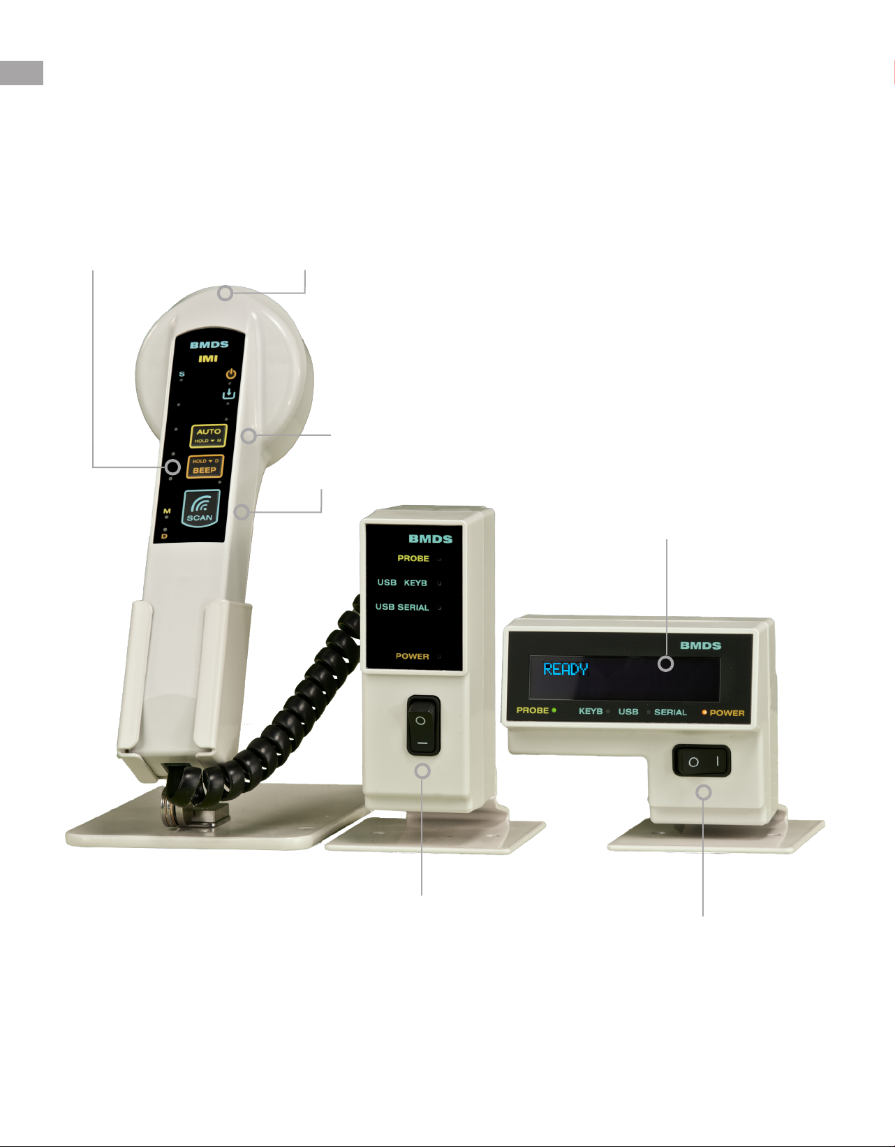
DAS-8010/20 WITH RSP-8004
6
OLED Display
Power/Scan Button
Reader Head
Auto Scan Button
Beep Button
Power Button

www.BMDS.com 1-800-526-BMDS or 302-628-4100 for Support Questions
7
SYSTEM OVERVIEW
The DAS-8010 and DAS-8020 must be connected to a smart probe to function. When connected, the DAS
unit and the RSP probe functions as a complete system. The system can also connect to the DASHost
software package for additional functionality. The software package allows for complete remote setup
of the DAS-8000 series RSP probes, scanning options, and data formatting options. DASHost and the
reader system can be used for creation of a MAP data le. For additional details on the RSP probe, please
refer to the probe section of the manual.
The DAS-8010 and DAS-8020 are our simplest solutions to connecting electronic animal identication to a
user’s computer or data collection software. To do this, the reader unit is paired with a BMDS Smart Probe;
currently available probes are either the RSP-8004 for the IMI-500 and IMI-1000 read only transponders
or the RSP-8005 for IPT-300 or IPTT-300 programmable transponder with temperature. Older legacy
6000 series smart probes can be connected but the full potential of the system will not be available in such
setups. The DAS unit’s primary role is to control incoming probe data and interface with a computer.
This manual will refer specically to the use of the DAS-8010 and DAS-8020 with the RSP-8004 Smart
Probe for use with the IMI-500 and IMI-1000 transponders.
The reader unit will also power and control the attached smart probe LEDs and advanced smart probe
functions. The new RSP-8000 series probes can now provide activation of autoscanning, duplicate lter
activation, and enable temperature on this specic smart probe model.

www.BMDS.com 1-800-526-BMDS or 302-628-4100 for Support Questions
SYSTEM SETUP
8
Setup instructions for both the DAS-8010 and DAS-8020 are exactly the same and extremely easy.
1. Unpack and inventory system components. There should be the DAS-8010/8020 reader unit,
a 12-volt power supply, an RSP smart probe, and a black RJ-11 coil cord for connecting the smart
probe to the reader system. A disc with the BMDS Serial USB Driver is provided for installation on
Windows XP through Windows 7 (Windows 10 provides native Serial USB support).
In addition, if ordered, there could be a USB data cable, a 9-pin Serial data cable, a smart probe
stand, and DASHost Utility Software.
2. Connect the unit to the 12-volt power supply. Plug the power supply to a standard outlet and
test for function by turning on the power switch located on the front of the unit. Turn the unit off after
conrmation. The LED is RED for OFF and ORANGE for ON.
NOTE: The power supply provided has a small BMDS sticker located on the bottom of the unit. It
has been calibrated to operate with all BMDS reader systems. DO NOT use non-approved power
supply units with your readers. Doing so could create interference with transponder reads, failure of
the sensitive smart probe or complete de-tuning of all equipment components.
3. Connect the RSP Smart Probe to the reader system. Using the supplied black coil cord, connect
one end to the back of the reader and the other end to the smart probe. This is a specially congured
6 pin RJ-11 cord provided by BMDS and not a standard phone or other similar in appearance cord.
BMDS cords have a reverse connection and special power handling capabilities. Do not substitute
coil cord for generic cord.
4. Connect the nal data cable from the unit to a functioning respective port on your computer.
The new DAS-8010 and DAS-8020 systems can now connect to your computer via three different
port options. Two modern USB options (Serial USB or Keyboard HID USB) and a legacy 9-pin
RS-232 serial connection. If connecting by either serial USB or RS-232, a BMDS driver will need
installation for systems running Windows XP through Windows 7. Windows 10 has native driver
support. Please contact BMDS for connections to Windows 8 and Windows 8.1.
5. Power on the system. Once all connections have been made, you can power on the complete
system using the power switch. In addition to the Power LED light, the probe LED and connection
LED will light to indicate that the system is functioning correctly.
6. Start to collect data reading the specic transponders tuned to your specic smart probe
reader.
NOTICE
The RSP-8004 is an IMI probe and can read only the IMI-500 and IMI-1000
transponder.

www.BMDS.com 1-800-526-BMDS or 302-628-4100 for Support Questions
SYSTEM COMMUNICATION OPTIONS
9
Connections
The DAS-8010 and DAS-8020 have three data connection options available for communicating with a
computer. There are two USB options and a 9-pin RS-232 serial connection for legacy computer system
support. Simply connect to the preferred port and note that the front LED automatically conrms connection.
The DAS-8010 has LED display connection for either Serial USB or Keyboard USB while the DAS-8020
has LED display for the three connection methods. It is best not to have more than one connection being
used at a time to avoid data collision.
SYSTEM NOTE: Although not necessary, BMDS DASHost software is suggested to allow for easy
communication with the computer and associated data collection software. DASHost will allow incoming
data from the reader to be transmitted as keyboard entries. Certain commercial software packages will
have serial COM port interfaces but most generic software such as Microsoft Word and Excel programs
do not.
Serial USB
Serial data output in a USB format is the preferred communication standard for secured data transfer.
Communication requires installation of a serial USB driver. The connected computer will assign a unique
COM port assignment for use with the data collection software. BMDS Custom USB Serial drivers are
provided for use with Microsoft Windows XP through Windows 7. Microsoft Windows 10 has native driver
support and needs no secondary driver installation. If needed, contact BMDS for Windows 8 and 8.1 driver
support.
Keyboard HID USB
Keyboard USB is the suggested connection for standard data transmission. The Keyboard USB or HID USB
requires no driver installation and can be used with any Microsoft Windows OS, Apple MAC OS, Android,
and Linux OS. Data transmission from this connection will appear as standard resulting keystrokes on
any active computer program window. Keyboard USB is therefore the simplest method to communicate
when connected to a computer, it should recognize the connection as a “human interface device” and
automatically congure the connection.
9-Pin RS-232 Serial Port
The DAS-8010 and DAS-8020 has an additional third output communication option. The units are equipped
with a standard RS-232 9-pin serial port. The port is congured for 9600 Baud, 8,1, None, and Flow
On. The settings can be updated by using DASHost to match the settings assigned by your computer
port hardware. RS-232 Serial Port allows for use with some legacy hardware systems that might have
restrictions on USB port access or driver installation limitations.

www.BMDS.com 1-800-526-BMDS or 302-628-4100 for Support Questions
USING DAS-8010/8020 WITH RSP-8004
10
The RSP-8004 is our newest generation of smart probes designed to be used in association with a wired
console system (DAS-8001, DAS-8010, and DAS-8020). The RSP probe receives power from the DAS
reader and is connected to the unit via the supplied BMDS RJ-11 Coil Cable. Once connected and powered,
the RSP smart probe can be used in conjunction with the IMI family of read-only transponders. The smart
probe will energize the transponder which will, in turn, send data back to the system. For optimal scanning,
the transponder should be separated from other transponders within the scanning area. The transponder
should be parallel with the unit but slightly in front and below the scan head. When the smart probe is
powered and the SCAN key pressed, the probe will search for a transponder in the scan radius (within 3”).
Once scanned, the probe will transmit the information to the DAS reader unit and connected computer.
There are several special shortcut buttons on the smart probe membrane keypad to allow for commonly
used functions. Additional set-up of the probe will require connection to BMDS DASHost Software.
www.BMDS.com 1-800-526-BMDS or 302-628-4100 for Support Questions
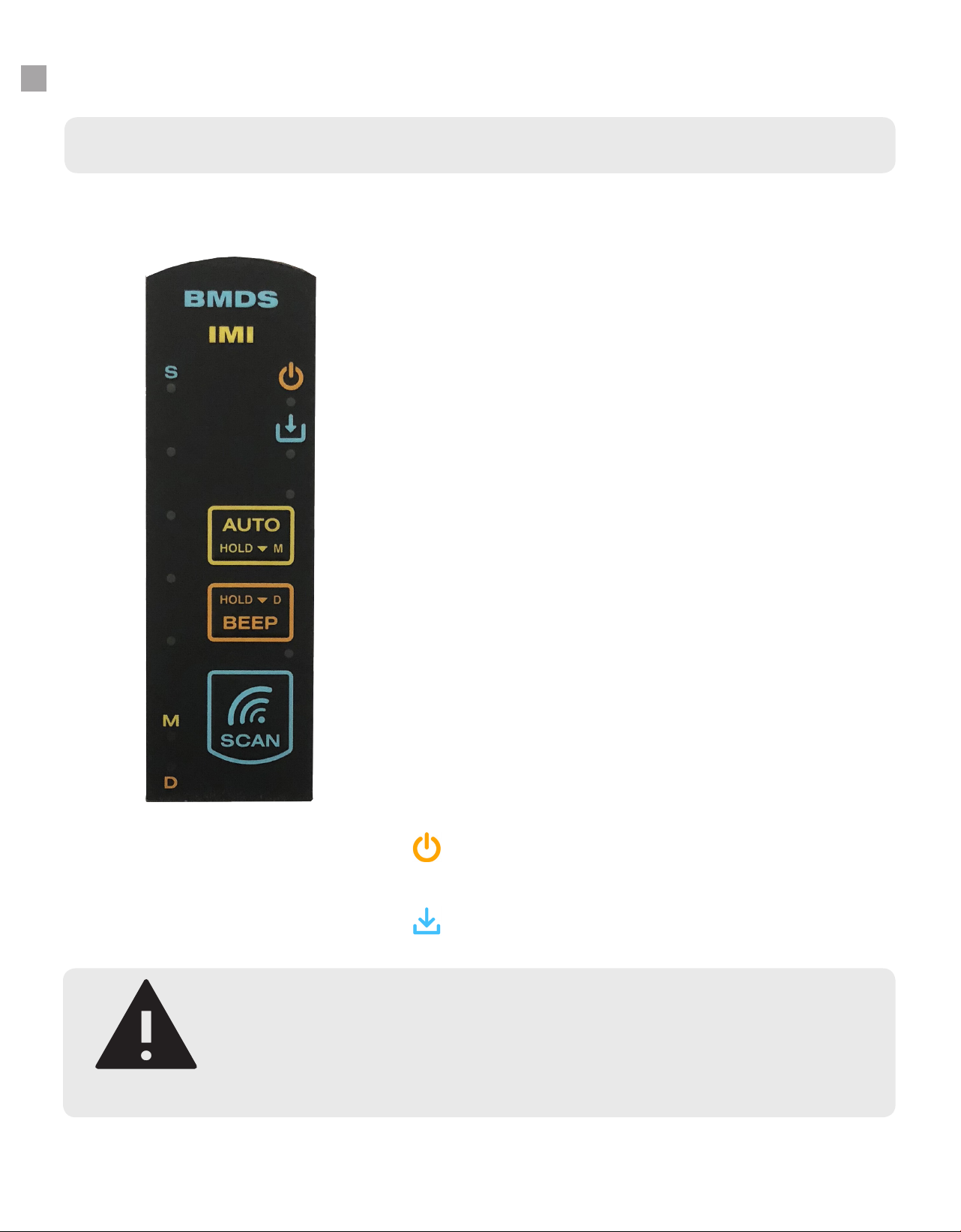
RSP-8004 KEYPAD AND DISPLAY
11
RSP-8004 Keypad
AUTO
A press of the button will activate autoscanning mode. While in autos-
canning mode, the probe will search for and scan a transponder. After
2-3 seconds, the probe will automatically return to scanning. The length
of time for autoscanning can be congured using a similar option in the
new DASHost 8000 software. Please refer to use of the smart probe with
DASHost 8000 on page 16 of the manual.
As a secondary feature, if the AUTO button is press longer, the map
function will activate. Mapping allows for associating the read-only IMI
transponder code with a user-assigned unique ID code. Please refer to
mapping section for creating and loading a map le. The M LED will also
be lit to indicate mapping feature. Holding down the AUTO button again
will deactivate mapping.
BEEP
A press of the button will activate or deactivate conrmation tone for
scanning. If the button is press down longer, the duplicate lter will be
activated. The D LED light will also be lit to indicate duplicate ltering.
While in this mode, the probe will prevent accidental duplicate con-
secutive reading of the same transponder. If the same transponder is
scanned on the following scan, a beep will alert user. Holding down the
BEEP button again will disable the duplicate lter function.
SCAN
A press of the button will activate scan mode. While in scan mode, the
smart probe will actively search for nearby transponders. The blue LED
lights along the side of the reader will scroll along with the top light la-
beled S for scan being on. To deactivate scanning, press the button
again.
Power LED Indicator light. When lit, smart probe is being pow-
ered by reader.
Data Transmission LED. When lit, scan data is being transmit-
ted to connected computer
The RSP-8004 membrane keypad includes several diagnostic LED indicators and three precongured
membrane buttons. Besides the SCAN button, there are two additional buttons that will activate unique
functions depending on if the button is pressed or held down for longer.
NOTE
While in scan mode or while in autoscanning mode, DO NOT place the probe on
a metal surface. Doing so for a prolonged period can cause the probe to become
overheated and de-tuned. De-tuning will reduce operational effectiveness and shorten
the lifespan of the probe.

www.BMDS.com 1-800-526-BMDS or 302-628-4100 for Support Questions
RSP-8004 READING MICRO-TRANSPONDERS
12
For optimal performance, the Micro-Transponder should be separated from other Micro-Transponders
within the scan area. The Micro-Transponder should be in line/parallel below the unit and slightly ahead of
the scan head. When the unit is activated via the SCAN key, the unit will continue to seek a transponder
until a transponder is read or the SCAN key is pressed again to cancel the scanning. The unit has various
features for displaying the collected transponder data, storing it, and sending out data ports.
Do not read the Micro-Transponder from the side or at right angles. Once again the general rule is to
have the length of the probe in line with the length of the transponder, about 2 to 3 inches away. A slight
movement away or towards the transponder will sometimes help.
NOTICE
Performance could be compromised if you attempt scanning the Micro-Transponder
at right angles to the reader. Also closer is not always better unless scanning a
transponder inside the needle assembly. The above information can also be applied
once the transponder is implanted. Note how the probe is above and slightly behind
the transponder. To do this successfully, it is important to be consistent as to implant
orientation. This makes it easier to imagine the location and orientation of the device
when out of view.

www.BMDS.com 1-800-526-BMDS or 302-628-4100 for Support Questions
RSP-8004 READING MICRO-TRANSPONDERS
13
While in a needle assembly, the read distance of the transponder is dramatically reduced to less than 0.5
inches. To best read a transponder in an applicator needle for scanning or mapping, use the following
technique. Place the “cap” directly onto the bullseye of the probe. You should get an instant read when the
needle assembly touches the probe.
An alternative method for reading the transponder involves placing the needle assembly at the 12 clock
position of the probe head. Using the ns on the cap as a guide to positioning. You should get an instant
read with this method also.

www.BMDS.com 1-800-526-BMDS or 302-628-4100 for Support Questions
CONNECTING TO DAS-HOST 8000
14
DASHost is now available as either DASHost 8000 supporting only the new DAS-8000 series readers or
DASHost 2.18 supporting both older legacy systems and the new DAS-8000 series equipment.
This manual will briey provide simple user instructions for use with the DASHost 8000 software only. The
reader system must be connected to the computer via the Serial USB port or 9-pin RS-232 serial port.
To start, connect to DASHost 8000 by following these steps to initiate communication with the computer.
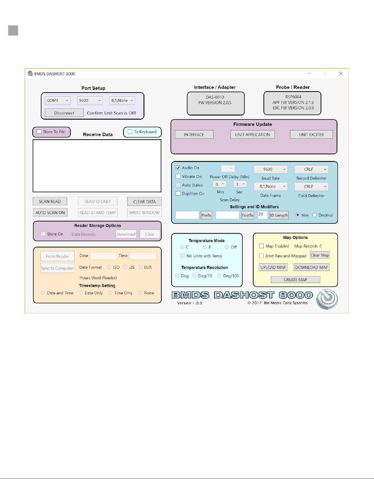
The new DASHost 8000 consist of several colorful window tabs with functions that are grouped together
for easier navigation.
1. Connect the reader system to your computer by either Serial USB or RS-232 port and turn reader on.
2. Open the DASHost 8000 program on your desktop.
3. If properly connected, there should be a COM port selection in the drop down menu available in the Port
Setup section. If multiple COM ports are listed, you will need to refer to Device Manager for Windows
in the Windows Control Panel folder to determine which to use. Most likely, the port assignment will
be COM4.
4. Connect by clicking Connect in Port Setup once the proper COM port has been selected.
5. The Interface/Adapter and Probe/Reader should display the correct reader and probe devices
connected. There will be a display of the current system rmware version for diagnostic if needed.
6. A quick conrmation of communication can also be veried by a simple scan using the reader and
smart probe. Data scanned will be displayed in the Receive Data box.
NOTE
If you do not see Interface/Adapter, Probe/Reader, or scanned data in the Receive
Data box, you are not communicating with your computer and will need to re-
attempt connection.
www.BMDS.com 1-800-526-BMDS or 302-628-4100 for Support Questions
CONNECTING TO DAS-HOST 8000
15
www.BMDS.com 1-800-526-BMDS or 302-628-4100 for Support Questions
USING DAS-HOST WITH RSP-8004
16
Once connected to DASHost 8000, the primary roles of the software will be for data collection and
communication with other software, conguring reader setup, mapping of IMI Micro-Transponders.
DASHost 8000 is capable of other utility tasks but those are not available with this reader system and
probe conguration.
Receive Data
Scanned data from the reader using the SCAN keypad on the smart probe will populate the data window
when connected. You can also manually select Scan Read button from within DASHost 8000 to initiate
scanning from the smart probe without pressing the SCAN keypad on the smart probe. The Read ID
Only, Read ID and Temp buttons, and Write Window are non-functional with RSP-8004 and IMI Micro-
Transponders.
• Scan Read button acts just like the SCAN keypad on the smart probe
• Auto Scan On can also be activated and is also similar to the AUTO on the probe keypad. NOTE: If
Auto Scan On is selected in DASHost 8000, the Auto Status button in the DASHost 8000 probe menu
section can be used to select a different scanning delay.
• Clear Data button will delete all collected data in the data box.
All data scanned will be displayed in the Receive Data box. The data can be stored to a le by clicking the
Store to File or sent to another open program such as Excel by clicking the To Keyboard. To Keyboard acts
in a similar manner as the Keyboard USB connection on the reader system.
Smart Probe Setup
The RSP-8004 has specic settings that can be updated by the new membrane panel of the smart probe.
Additional options not available from the smart probe can be access and congured using DASHost 8000.

www.BMDS.com 1-800-526-BMDS or 302-628-4100 for Support Questions
USING DAS-HOST WITH RSP-8004
17
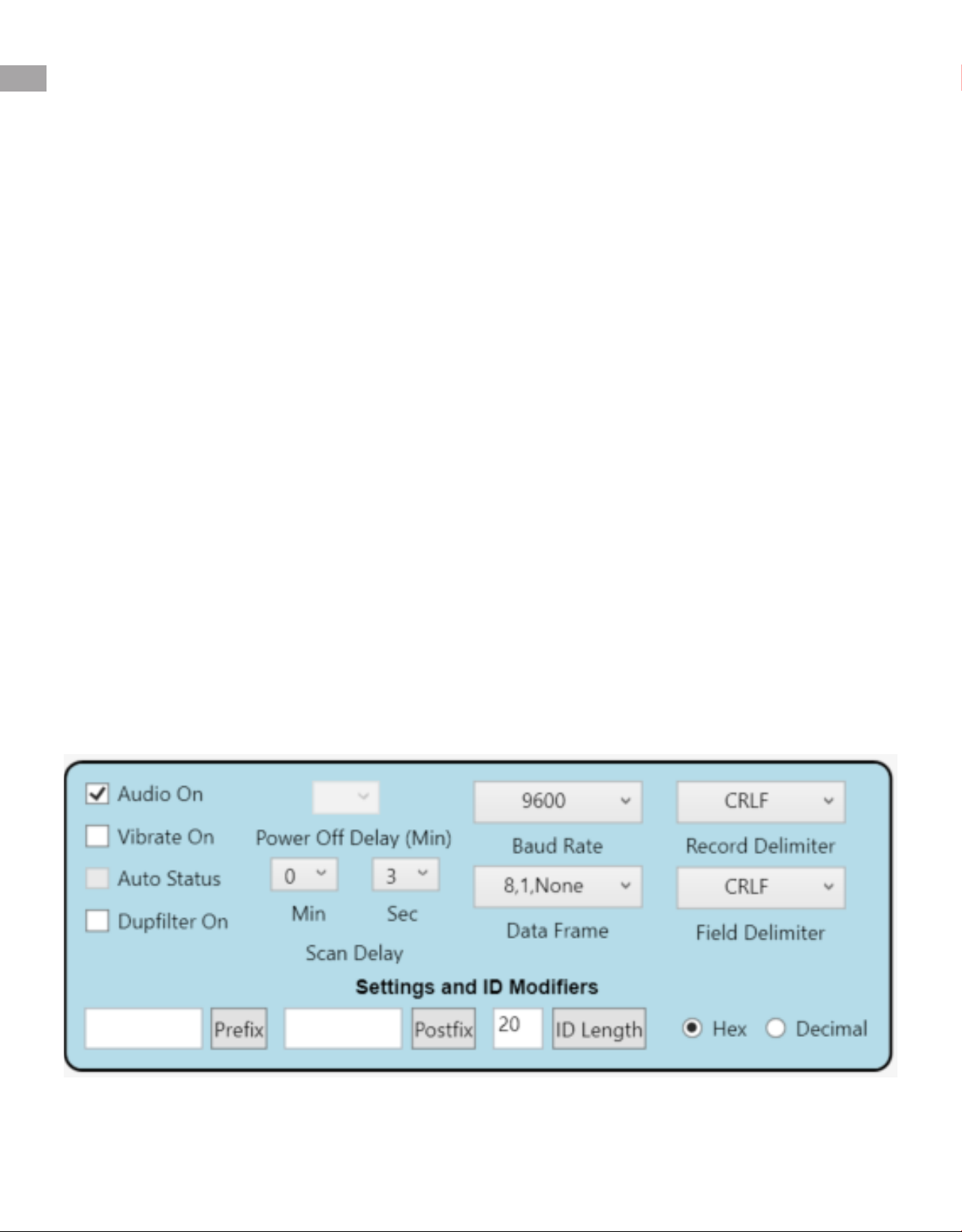
Audio On, Vibrate On, and Duplter On: These settings are similar to the available options on the smart
probe with the exception of Vibrate which can be activated only from DASHost 8000. Grayed out options
will not affect the system such as Auto Status (only active with Auto Scan On selection from DASHost 8000
using the selection button in the Receive Data window). Lastly, Power Off Delay is grayed because it does
not function with AC powered units.
Baud Rate and Data Frame: The default for near universal conguration is 9600 Baud, 8,1,None for Data
Frame Rate. If you nd a need to recongure communication to function better with your computer, the
settings can be updated in DASHost 8000.
Field Delimiter: This tab will allow you to select the delimiter character or characters that will be sent
between elds of data from the probe.
The available delimiters are:
• CRLF – This will transmit two characters for the delimiter: a Carriage Return character (ASCII 13) and
a Line Feed character (ASCII 10).
• TAB – This will transmit a Tab character (ASCII 9).
• COMMA – This will transmit a comma character (ASCII 44).
• CR – This will transmit a Carriage Return character (ASCII 13).
• NONE – No delimiter transmitted with sent data.
Record Delimiter: This tab will allow you to select the delimiter character or characters that will be sent
between records of data from the probe.
The available delimiters are:
• CRLF – This will transmit two characters for the delimiter: a Carriage Return character (ASCII 13) and
a Line Feed character (ASCII 10).
• TAB – This will transmit a Tab character (ASCII 9).
• COMMA – This will transmit a comma character (ASCII 44).
• CR – This will transmit a Carriage Return character (ASCII 13).
• NONE – No delimiter transmitted with sent data.
EXAMPLES of Data Format using TAB for Field Delimiter and CRLF for Record Delimiter:
4A52676D37 Animal0001
4A53276E51 Animal0002
EXAMPLES of Data Format using CRLF for Field Delimiter and CRLF for Record Delimiter:
4A52676D37
Animal0001
4A53276E51
Animal0002
Settings and ID Modiers: Allows for adding a prex or postx and transmission of specic ID size of the
transponder code if required by the data collection software used by the facility.
www.BMDS.com 1-800-526-BMDS or 302-628-4100 for Support Questions
MAPPING WITH RSP-8004
18
Mapping is the process of associating a read-only transponder ID code (i.e. 4A63D23037) with a user
assigned unique code. The smart probe will read a transponder ID, then instantly search for the transponder
ID in the stored map le assignment. If a match is found, the reader will either return the associated map
code in place of the transponder ID or both the transponder ID and map code. The map codes are stored
on the smart probe in the internal memory and is known as a map le. A map le is a collection of records
where each record contains a transponder ID and a map code that is associated with the transponder ID.
Example Map File:
4C07507E4F/Animal 10001
6D5E54080B/Animal 10002
6D6F45053D/Animal 10003
4C0730056C/Animal 10004
6D5471787D/Animal 10005
Mapping is activated on the smart probe by holding down and releasing the SCAN button. The M LED will
light to indicate that scanned transponders will either show the mapped ID or the read-only. You can also
elect to show both the read-only code and mapped ID by using the DAS-Host software Toolbox settings.
Creating a Map File
Mapping of transponder ID is done using the DASHost 8000 Software and your DAS-8010 or DAS-8020
and a RSP-8004 smart probe. The reader system must be connected to the computer via the Serial USB
port or 9-pin RS-232 serial port.
Locate Map Options in the lower right-hand side of the application. Click Create Map to start the process.
When creating a map le, the default extension should always be left as .MAP.
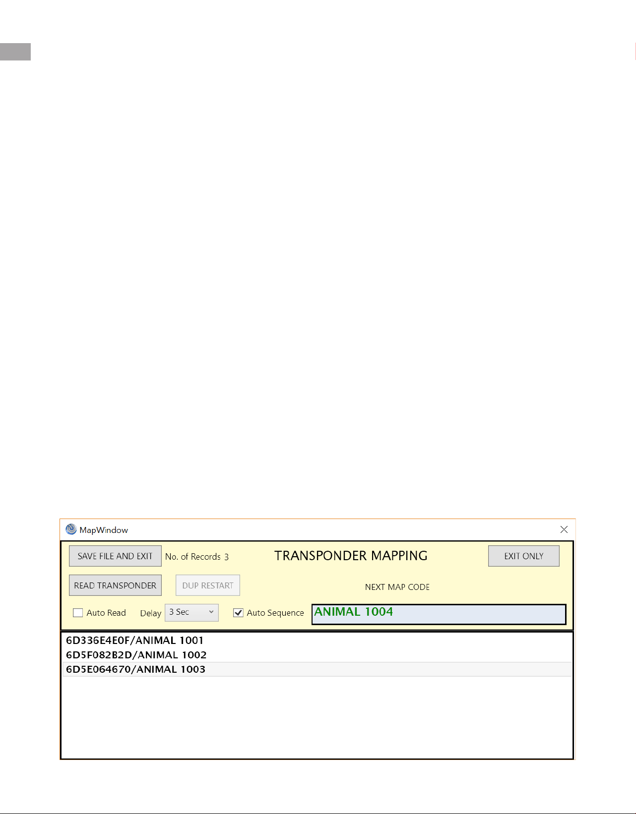
Once initiated, the following window will open to begin the process of linking a user assigned ID to the IMI
read-only code.

www.BMDS.com 1-800-526-BMDS or 302-628-4100 for Support Questions
MAPPING WITH RSP-8004
19
Under Next Map Code, enter in your desired ID code (example: RAT 001). If the last character is a number,
the program will sequentially assign the next sequential number for each new transponder mapped. Auto
Sequence will be checked by default. If consecutive numbering is not desired, manually uncheck the Auto
Sequence box.
Press Read Transponder in the window and scan your rst transponder. If you plan to map a series of
consecutively numbered transponders, you can check the Auto Read box and select a delay between
scans (default is 3 seconds). Scan your 1st transponder. Your number should drop into the window for
each transponder scanned, showing both the IMI factory code and the new mapped code.
Once completed.Select Save File and Exit to create a MAP le. If a current existing MAP le is entered,
the le will be updated with the new entries. Select Exit Only if the mapping session was not needed.
To send this same le directly to the RSP-8004 smart probe, follow the instructions below.
Sending a Map File to the RSP-8004
Once a map le has been created, use DASHost 8000 to send the map le to the RSP-8004 probe. Click
Upload Map to select a map le to transmit to the smart probe. Once uploaded, the probe will automatically
activate MAP display which can be unchecked from DASHost 8000 or by holding the AUTO button on
the probe. DASHost 8000 will also report the total number of Map records currently on the probe. If the
original MAP le located on the computer should ever be lost, you can reverse the transmission and
Download Map from the probe to the computer.
A MAP le can also be cleared out of the probe by selecting Clear Map on DASHost 8000.

www.BMDS.com 1-800-526-BMDS or 302-628-4100 for Support Questions
NOTES
20
This manual suits for next models
1
Table of contents


