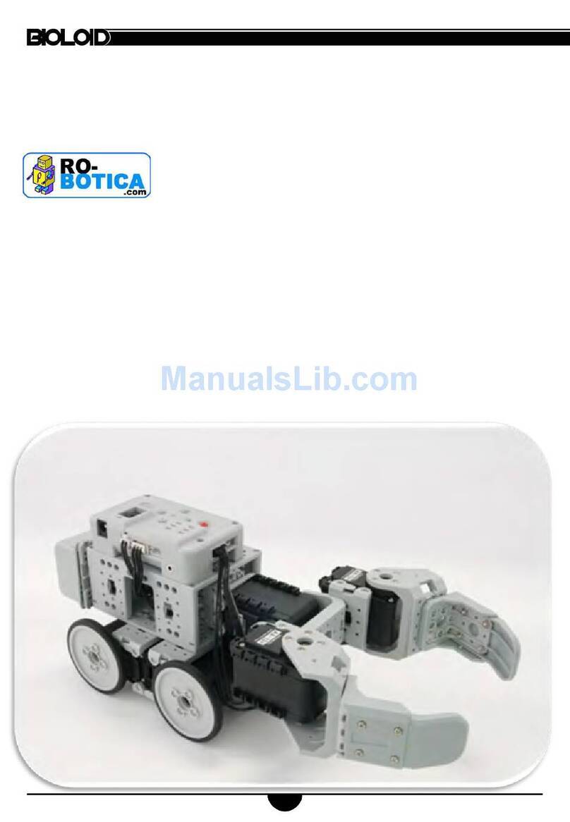
Bioloid Robotis User manual

Ver 1.00
BIOLOID
User’s Guide
Closer to Real

User’s Guide
Contents
1. Before Starting
1-1. A Word of Caution Page 4
1-2. What is Bioloid? Page 6
1-3. Things to Understand Before Starting Page 8
1-4. Package Contents Page 11
2. Learning the Basic Operations
2-1. The CM-5 and Its Operation Modes Page 13
2-2. Behavior Control Program Page 15
2-3. Examples of Simple Behavior Control Page 17
2-4. Understanding ID, Address, and Data Page 27
3. Assembling Basic Robots
3-1. Connecting Frames Page 32
3-2. Wiring and Power Page 33
3-3. Frequently Used Behavior Control Routines Page 35
3-4. Assembling Robot Arm Page 37
4. Behavior Control Programmer
4-1. Opening a File Page 43
4-2. Editing Function of the Behavior Control Programmer Page 44
4-3. Syntax of the Behavior Control Program Page 49
5. Reciprocal Operation Using Sensors
5-1. The AX-S1 Sensor Module Page 56
5-2. Distance Sensing Function Page 57
5-3. Sound Sensing Function Page 58
5-4. Assembling Attacking Duck that Uses Sensor Page 59
5-5. Surrounding Light Sensing Function Page 64
5-6. Melody Playing Function Page 65
5-7. Assembling Intelligent Car that Uses Sensor Page 68
6. Motion Editor
6-1. Using the Motion Editor Page 75
6-2. Motion Editing Using the Robot Terminal Page 84
6-3. Walking Droid Robot’s Program Page 91
2

User’s Guide
7. Building a Wireless Remote Control
7-1. Infrared Communication Program Using the AX-S1 Page 97
7-2. Building RF Wireless Remote Control Using the ZIG-100 Page 101
7-3. Walking Droid Program Controlled by the RF Wireless Remote Control Page
105
8. Management Mode
8-1. Setting the ID and Dynamixel Search Page 108
8-2. Other Commands Page 111
9. Information for Advanced Users
9-1. Boot Loader Page 116
9-2. Using the C Program Language Page 119
9-3. Compiling Page 120
9-4. Example.c Page 126
10. Bioloid Program Update
10-1. CM-5 Program Update Page 135
10-2. Dynamixel AX-12 Program Update Page 139
3

User’s Guide
1. Before Starting
1-1. A Word of Caution
A Note on Safety
The user is responsible for any accidents that occur while building the robot. Before
starting, please remember the following.
Read and study the manual before starting.
The recommended age for this product is 12 years and older. Those under 15
years must work under supervision.
Only use the recommended tools and do not use any dangerous tools, such as
knives or drills.
Do not work on this product if you are feeling sick or feel fatigue, and especially
under influence of alcohol.
Keep the robot away from your face.
Keep the robot or its parts away from children.
Be careful not to get your finger be caught between the joints.
The product is not waterproof so be cautious when handling near water.
Only operate the robot indoors.
Do not operate or store it in under direct sunlight.
Do not operate or store it near open flames or in humid environments.
Robot Malfunction
If any of the following occurs, immediately turn off the power and contact a
supervisor or the company.
When you see smoke coming out of the product.
When the LED does not blink after power is connected.
When water or foreign substances enter the robot.
When you detect an unnatural smell from the product.
When the robot is damaged.
Recharge Problem
After powering on, when you connect to SMPS and press ○
U button, the Power LED will
blink and will began recharging. If there is a problem with recharging, make sure that
fuse is not out. [Refer to the QuickStart for exchanging a fuse]
4

User’s Guide
Notes Please note the following.
The beginner should not use self-made cables.
Only use the right size screw drivers.
Do not use excess force when tightening the bolts or assembling the parts.
Turn off the power immediately to avoid damage to the robot if a joint gets
twisted caused by the inappropriate motion settings during development.
If this is the first time you are building a robot, please build a robot in the
QuickStart following the instructions. A custom-built robot should only be
attempted if you have at least six months experience with the robots.
To prevent the robots from falling, do not place the robot on a high location such
as on top of a table or desk. Always operate the robot on the ground. If the robot
is damaged due to a fall, it will be ineligible for free repair.
The joints of the robot and the gears inside the Dynamixel are susceptible to
wear. After a period of time, the backlash of the robot will increase, especially if
excessive load is applied.
When operating the robot with the SMPS, make sure the robot doesn’t fall and
refrain from excessive movements. This can cause the SMPS cable to break.
Recommended Tools
Phillips head screwdriver: M2 size
Flat head slotted screwdriver: Use if the bolt’s groove wears out. Do not use
any other tools. The use of dangerous tools can cause accidents.
Building a Robot
Don’t attempt to make a robot with more than ten joints if you are a beginner.
You may need many practices before trying to build a complex robot.
This User’s Guide shows how to build the Robot Arm (3-degree of freedom), and
the Walking Droid(4- degree of freedom).
5

User’s Guide
1-2. What is Bioloid?
Bioloid The Bioloid is a robot kit where the user can build anything they desire, just like
the Lego sets. But unlike the Lego sets, the robot is built with blocks that are
actuated, so the joints can move. The name “Bioloid” comes from the
words“Bio” + “all” + “oid” meaning that any living thing can be built in the
form of a robot.
The following are some examples of what can be built with the Bioloid kit. In
addition to below, many other forms of robots can be built.
[Examples of Bioloid Robots]
Function With the use of a distance sensor, sound sensor, and feedback from the joints,
the robot can be programmed to operate autonomously. For example, you can
build a robot dog that gets up when it hears a clap and sits down when it hears
two claps, or a robot that bows when a person comes close. You can also make a
robot that avoids obstacles or a robot that plays with a ball. A robot that can
move by the pressing of buttons or by using the remote control (option) can also
be built. Using the provided software, even people without a background in
robotics can easily program these kinds of robot movements.
6

User’s Guide
1-3. Things to Understand Before Starting
Before putting the robot together there are a few basics that you have to
understand. First of all, let’s study about the Bioloid’s hardware and software.
The terms used here will be mentioned often throughout the manual so it is
important that you understand them.
Hardware The hardware of the Bioloid consists of three types.
Dynamixel: This is the basic unit of the Bioloid which acts as a joint or a sensor.
The AX-12 Dynamixel is an actuator that is used as a joint. The AX-S1 Dynamixel is
a sensor unit that can sense both distance and sound.
CM-5: This is the main controller of Bioloid robot. Batteries that are placed here
supply power to the connected Dynamixel.
Frame: The frame connects the robot units. The Dynamixel can be connected
together with the use of the frame. Also, the frame connects the Dynamixel and
the CM-5.
Software There are three pieces of software supplied for use with the Bioloid.
Behavior Control Programmer: This is used for creating a program that controls
the robot behavior. The program is used to implement the motion the robot
follows according to the information received through input devices such as
sensors.
Motion editor: It is not easy constructing the complex motion of multi-joints
robots with the Behavior Control Programmer only. Motion Editor is software that
helps the creation of robot motions and that calls it whenever it is required.
Robot Terminal: This is a type of a serial communication terminal program where
advanced users often use to see information displayed on the screen sent by the
robot and also to send the characters typed on the keyboard to the robot.
Frame
CM-5 Dynamixel
7

User’s Guide
Assembling Process
The step of developing a Bioloid robot
Read the User’s Guide
Step 1
Decide the configuration and function of the robot
Step 2
Connecting the Dynamixel units around the CM-5
Step 3
Cable connection (beware of connector direction
Step 4 and length of the cable)
Simple motion verification (use Motion Editor)
Step 5
Behavior control programming
Step 6
Step 7 Editing the motion (use Motion Editor)
Step 1 Read and completely understand the manual before trying to build a robot. The
manual consists of nine chapters and the first five chapters are intended for
beginners. The User’s Guide presents examples of developing the Robot Arm and
the Walking Droid (two-legged robot). Once you have completely understood the
User’s Guide, you can explore various robot configurations and experiment with
the program in depth.
Step 2 This is where you decide what kind of robot you will be building. With the Bioloid
kit, you can make all kinds of robots. If you are a beginner, however, we
recommend that you first make the robot that is shown in this User’s Guide.
Step 3 Step 3 is the building stage. First, connect the Dynamixel units to the CM-5 unit as
the center unit. Connect other Dynamixel units to this to create joints and expand
to complete the robot. Secure each part with nuts and bolts.
8

User’s Guide
Step 4 After the configuration of the robot is completed, the next step is to connect the
cables. Having the CM-5 unit as the center, the wires are connected to, and
through the Dynamixel units. Each cable is made up of three wires. Two of the
wires are for power and one is for communication. Make sure the cables are long
enough so that they allow the joints to bend all the way in either direction.
Connect the cables in a daisy chain fashion as shown in the figure below.
Control Box “CM-5”
The steps up to here complete the building of the robot hardware. The
configuration of the robot is decided in Steps 1, 2, 3, 4 and the function of the
robot will be decided through programming in Steps 5, 6, 7.
Step 5 After you are done building the robot, use the motion editor program to make
sure the robot is properly put together. Make sure all the Dynamixels are
communicating with the CM-5 unit properly. To check if the joints are working
properly, test them by moving each of the joints slightly.
Step 6 In step 6, you will create the behavior control program of the robot. Behavior
control is simply telling the robot to take some kind of action when it enters a
certain state. For example, when the robot is walking forward through a narrow
path, you can make it walk through the center of a path. Or, if there is something
blocking the way, you can make it turn around and go the other way. The behavior
control program takes the form of rules which defines the appropriate motion the
robot should output for specific input information it receives from the sensors.
Step 7 In step 7, you will create the motion of the robot. For robots that use wheels, step
7 is unnecessary because all you have to do to move the wheels is to set the
position or velocity settings of the Dynamixel. But it would be difficult to make a
puppy robot sit or a humanoid robot walk by changing each of its joint angles
individually. In order to move a complicated multi-jointed robot, you have to
“call” a pre-made movement.” This “pre-made movements” (motions) are
what you will create here in step 7. The behavior control program of step 6 will be
able to “ call” these “ pre-made movement ” (motions) of step 7. Step 7
shouldn’t be taken after you are done with step 6, but rather together with step 6.
9

User’s Guide
PC Requirements
PC : IBM compatible (Required)
OS : Windows 2000 or Windows XP (Required)
CPU: Intel Pentium III 1GHz or AMD Athlon XP 1GHz or higher (Recommended)
RAM: 256MB or higher (Recommended)
Graphic Card : 3D acceleration function (Direct 3D supported) (Required)
HDD free space : at least 300MBytes (Recommended)
Direct X 8.0 or higher (Required)
10

11
User’s Guide
1-4. Package Contents
(Beginner kit’s parts)
CM-5
motor
ADAPTOR-CM5
1
AX-12×4
motor
4
AX-S1
~
×1
×1
F1 ×4 F3 ×12
F8 ×2 F12×2
N1 ×150
S4 ×20
S-B
×10
BU ×6 WA ×6
CABLE-6
CABLE-10
×2
※ Nuts, screws, and cables shown below are the same as the actual size. Place and measure the parts against the below
illustration to choose the correct assembly part.
STICKER ×32
S3 ×20
F2 ×4 F4 ×2 F5 ×1 F6 ×4
F9 ×3 F10
×10 F11×2 F13
×4 F14
×4
SP1
×4 SP2×4
S1 ×150
S2 ×20
S5 ×20
CABLE-14
CABLE-18
CABLE-20
×3
×2
×1
×1
×1
SMPS Serial Cable CD
FUSE ×1
QuickStart

12
User’s Guide
(Comprehensive kit’s parts)
CM-5
ADAPTOR-CM5
motor
1
AX-12 ×18
motor
18
AX-S1
F1 ×10 F3 ×20
F8 ×3 F12×2
N1 ×400
S4 ×20
S-B
×30
BU ×20 WA
×20
CABLE-6
CABLE-10
×6
※ Nuts, screws, and cables shown below are the same as the actual size. Place and measure the parts against the
below illustration to choose the correct assembly part.
STICKER ×32
S3 ×20
F2 ×10 F4 ×6 F5 ×6 F6 ×12
F9 ×5 F10
×20 F11×2 F13
×4 F14
×4
~
Expansion PCB
F7 ×6
SP1×4 SP2×4
F15
×1 F16
×1
N2 ×10
S1 ×400
S2 ×20
S5 ×20
S6 ×20
S7 ×20
S8 ×20
CABLE-14
CABLE-18
CABLE-20
×4
×6
×4
×5
×1
×1
×1
×1
SMPS Serial Cable CD
FUSE ×1
QuickStart

User’s Guide
2. Learning the Basic Operations
2-1. The CM-5 and Its Operation Mode.
CM-5 The CM-5 is the main controller for the Bioloid. As mentioned previously, the robot
is built by connecting the Dynamixels to the CM-5 as the central unit. In order to
understand how the Bioloid works, you first have to understand how the CM-5
operates.
Serial Cable Jack
POWER Status display LED
Applying Power Let’s now apply power to the CM-5 unit. Plug the SMPS into the power jack on
the upper left corner. Then turn the power switch on. One of the mode display
LEDs should be blinking. As you press the mode change button, the mode LED will
change sequentially. Currently, it is in standby mode.
Operating Modes The operating modes of the CM-5 unit is as follows
Manage mode: This is used when you want to know the status of the CM-5 unit or
the Dynamixels, or when you want to test the motion. This mode should only be
used by advanced users who are very confident with operating the robot.
Program mode: The mode used for editing the motion.
Play mode: The mode used for running the behavior control program created.
Standby mode: The mode before running the other three modes.
Charging mode: In standby mode, if the SMPS is connected, battery charging will
begin when you press the ○
U button.
[Top view of the CM-5
Power JACK
Start button
Mode button
Direction buttons Mode display LED
13

User’s Guide
Execution If you press the start button during standby mode the CM-5 unit will go into the
mode that you have selected. To go back into standby mode you can press the
mode change button or turn the power switch off and then back on again.
TIP The mode change button is the reset button for the CPU inside the CM-5 unit.
Therefore, when the power is on, the CM-5 will go back to standby mode
whenever the mode change button is pressed.
Serial Cable In order to communicate with a PC, the CM-5 unit has to be connected to it using
a serial cable.
When using a laptop: Most laptops do not have a serial port, thus you will have to
purchase and use a USB to serial converter device. USB2Serial can be purchase
at local computer stores.
Status Display LED
There are the four LEDs that indicate the status of the CM-5 unit. The definitions
of each are as follows.
Power: If the power is on, this LED will be on. The LED will blink when the batteries
inside the CM-5 unit are charging. Recharging starts when the SMPS is connected
to the power jack and the ○
U button is pressed in standby mode.
TXD: This LED is on when the CM-5 unit is transmitting data.
RXD: This LED is on when the CM-5 unit is receiving data.
AUX: This LED is assigned for user programming. It can be turned on or off with the
behavior control program.
Direction Buttons
These buttons are also assigned for user programming like the AUX LED.
14

User’s Guide
2-2. Behavior Control Program
A robot is a machine that can behave in various ways. However, it can do so only
when there is a program that tells how the robot should act for a certain
situation. This program is called the “behavior control program.” A behavior
control program is a series of rules that define the action a robot should take for
the given state. Insert the provided CD into the PC and install the software used
for creating the behavior control program.
Installation You can install following three programs.
Behavior Control Programmer
Motion Editor
Robot Terminal
The following screen appears when you run the behavior control programmer.
Input and Output The behavior control program takes the form of a series of rules that mutually
connect the input and output. For example, let’s say that we want to build a
robot dog that stands up when you clap once and sits down when you clap twice.
The input item (clap once or twice) and the output item (stand up or sit down)
have to be predefined. Also, behavior rules need to be defined that tells what
behavior to output for the given input item (clap once or twice).
15

User’s Guide
The followings are the general expression sentences for these behaviors.
If input item 1 occurs, then execute output A.
If input item 2 occurs, then execute output B.
Thus, understanding what types of input and output items are available is
important to writing a behavior control program. Learning how to use the Bioloid
is to learn about the input and output items. Let’s practice creating a simple
behavior control program using the CM-5 unit’s input and output items now.
16

User’s Guide
2-3. Examples of Simple Behavior Control
There are several buttons and LEDs on the CM-5 unit that is user definable. Five
out of the total six buttons (except the mode change button) and the AUX LED can
be used for such purposes in Behavior Control Programmer.
AUX LED
Start button
Mode button
Direction buttons Top view of the CM-5
Let’s create a behavior control program as the following.
Make a program that will turn on the AUX LED when the ○
U button is pressed and
turn off the AUX LED when the ○
D button is pressed.
Create a new file from the Behavior Control Programmer, as shown in the figure
below.
The following screen will show up.
Select
17

User’s Guide
“Start” Left double-clicks the first cell in the Behavior Control Programmer. The following
commands should appear. Select “START.”
The “START” command does not instruct a specific action, but rather it tells
that the program is starting. You can see that the first cell is used for
commands. There are around ten commands that are available for the behavior
control program and we have already learned one of them.
“If” The command that we want to input is “if the ○
U button is pressed.”
18

User’s Guide
Double-clicks the first cell of the following line and select the command “If.”
Parameters There are some commands that need to be used together with a number or
symbol. For example, the command “START” does not require any number or
symbol to be used with, but the a command like “compute 1 + 2” requires the
numbers “1”,“2” and the symbol “+.” The command “If” compares two
items so it requires several parameters. Let’s implement the input command “IF
○
U is pressed” using several parameters.
“IF (button status = ○
U button) then”
As mentioned earlier, in order to understand and program a behavior control
program, you have to learn about the available input and output items. Here, we
have to find the “○
U button”input item that has been used as a parameter.
To select the button status parameter, double-clicks on “undefined” and select
CM-5. Then select the “CM-5 button” item.
[Select CM-5 first.] [Then select item]
19

User’s Guide
Now select the ○
U button. Double-click the parameter on the opposite side and
check the location of the ○
U button.
The next step is to select the operator that compares the two parameters. Select
the equal sign.
Finally, select the undefined item and double-click “THEN.”
20
Table of contents
Other Bioloid Robotics manuals
