Biomet 3i Navigator Reference guide
The Parallel Walled
Navigator®System For Guided Surgery
Procedure Manual


Navigator®CT Guidance: Steps to Success ................................................................................................................................... 1
Getting Started............................................................................................................................................................................... 3
Introduction And Treatment Planning ............................................................................................................................................. 4
Instrumentation Overview ............................................................................................................................................................. 5
Surgical Plan Overview................................................................................................................................................................... 9
Tips And Techniques ................................................................................................................................................................... 10
Immediate Provisionalization Option ............................................................................................................................................ 12
Fabrication Of A New Denture Or Partial Denture And CT Scanning Appliance ........................................................................... 13
Fabrication Of CT Scanning Appliance Using An Existing Denture ................................................................................................. 15
Pre-Surgical Fabrication Of An Edentulous Fixed Provisional Restoration........................................................................................ 16
Pre-Surgical Fabrication Of A Partially Edentulous Fixed Provisional Restoration ............................................................................. 17
Cement-Retained PreFormance®Post .......................................................................................................................................... 18
Cement-Retained Provide®Abutment And Temporary Cylinder ................................................................................................... 20
Screw-Retained Low Profile Abutment And Temporary Cylinder ................................................................................................. 22
Screw-Retained PreFormance Temporary Cylinder....................................................................................................................... 24
Combination Cement / Screw-Retained QuickBridge®Restoration And Low Profile Temporary Cylinder Multiple-Unit Only..........26
Table Of Contents

1
IMMEDIATE
PROVISIONAL
DESIRED?
1. The scanning appliance may be created from an existing
denture or new wax-up to visualize the soft-tissue and
tooth position in the third party planning software chosen.
2. A CT scan of the patient is taken by an imaging center or
in the clinician’s office. Data from the scan is converted into
the planning software.
3. The clinician plans the case within the planning software
and the case plan is sent to the surgical guide manufacturer.
Fixation of the guide can also be planned at this time.
a. The software company may act as the surgical guide
manufacturer or
b. A laboratory may create the surgical guide.
4. The surgical guide manufacturer develops a case-specific
surgical plan and surgical guide.
5. The surgical plan and surgical guide are sent to the dental
laboratory or restorative doctor and used in conjunction
with the Parallel Walled Navigator
Laboratory Kit (if no immediate provisional is desired,
go to step 8).
6. The master cast is poured into the guide or the implant
analogs are placed in the preoperative cast on a partially
edentulous case using the guide.
7. The abutments are selected and the provisional prosthesis
is fabricated and sent to the clinician.
8. The surgical guide and surgical plan are sent to the
surgeon and used in conjunction with the Parallel Walled
Navigator Surgical Kit.
9. The surgical guide is placed and may be fixated with 2mm
fixation screws.
10. The clinician will prepare the site(s) with the case-specific
surgical plan and surgical guide for implant placement with
the BIOMET 3i Parallel Walled Navigator Surgical Kit.
11. The implants are placed through the surgical guide.
12. The Implant Mounts and surgical guide are removed.
13. If a traditional procedure is desired, a one or two-stage
procedure is completed and a traditional provisional
prosthesis – denture/Maryland Bridge/flipper partial – may
be delivered.
14. The abutments and the provisional prosthesis are delivered.
15. The patient is able to go home that day with a brand
new smile!
1
2
3
4
5
8
Navigator®CT Guidance: Steps to Success

2
Photos courtesy of Dr. Harold Baumgarten†, Philadelphia, PA and Dr. Alan Meltzer†, Voorhees, NJ
NO
YES
TRADITIONAL
PROCEDURE
IMMEDIATE
PROVISIONAL
10
67
911 12
14
15
IMMEDIATE
PROVISIONAL
DESIRED?
13
†Dr. Baumgarten and Dr. Meltzer have financial relationships with BIOMET 3i LLC resulting from speaking engagements, consulting
engagements and other retained services.

3
Getting Started
In order to utilize the Parallel Walled Navigator®System,
clinicians will need to purchase CT planning software from
one of the planning software companies and have access
to a CT scanning facility. Training on how to use the CT
planning software chosen is essential for all clinicians and
technicians involved in case treatment-planning. In addition,
laboratory technicians will need to obtain the Parallel
Walled Navigator System Laboratory Kit to fabricate
the preoperative master cast and clinicians will need to
obtain the Parallel Walled Navigator System Surgical Kit to
place the implants. The complete system overview that
describes each instrument and component included in the
kits and their associated use begins on page 5.
Prior to sending the patient to the CT scanning facility,
a radiopaque scanning appliance may be fabricated to
show the desired tooth position of the restoration when
seated in the mouth during the CT scan. Pages 13-17 in
this manual are designed to guide surgeons, restorative
clinicians and laboratory technicians through the process of
fabricating a scanning appliance from an existing denture, a
newly fabricated denture or a diagnostic wax up.
A page with tips from clinicians who evaluated the
system prior to market release is also included in this
manual on pages 10-11. These tips will help to ensure
a smooth process from CT scan to the day of surgery
and provisional delivery when using the system and may
reduce the learning curve associated with use of the
Parallel Walled Navigator System For
Guided Surgery.
Open Architecture System
The Parallel Walled Navigator System is designed to allow
clinicians to place and provisionalize BIOMET 3i Dental
Implants using a variety of compatible CT planning software
and surgical guides. The system is open architecture to be
compatible with the current software and surgical guide
providers listed below.
Materialise Dental, Inc.
810-X Cromwell Park Drive
Glen Burnie, MD 21061
United States
(443) 557-0121
www.materialisedental.com
Materialise Dental, NV
Technologielaan 15
3001 Leuven
Belgium
+32 16 39 66 20
iDent – US
2652 NW 31st Ave
Ft. Lauderdale, FL 33311
United States
(954) 495-8684
www.ident-surgical.com
iDent – Israel
4 Yohanan Street
Box 6402
Hod Hasharon 45241
Israel
+972-52-546-2366
www.ident-surgical.com
SICAT Gmbh + Co. KG
Brunnenallee 6
D-53177 Bonn
Germany
+49-228-854-6970

4
Introduction And Treatment Planning
This manual is designed to serve as a reference
guide for dental practitioners to utilize
Restorative Components and
instruments. BIOMET 3i Implant Systems have
been developed to meet the diverse needs of
patients and to offer practitioners a choice of
customized restorative techniques.
BIOMET 3i Implant and restorative component designs
provide practitioners with a wide range of restorative
options, including support for single tooth crowns, fixed
and removable prostheses and attachments for securing
overdentures. BIOMET 3i Implant and Abutment Systems
utilize proven restorative designs and provide clinicians and
patients with predictable treatment options.
General Information
This manual provides guidelines for surgical and restorative
practitioners and laboratory technicians in the use of the
BIOMET 3i Navigator®System For Guided Surgery. The
success of any dental implant system depends upon proper
use of the components and instrumentation. This manual is
not intended for use as a substitute for professional training
and experience.
Treatment Planning
Patient Evaluation And Selection
Several important factors must be considered when
evaluating a patient prior to implant surgery. The
presurgical evaluation must include a careful and detailed
assessment of the patient’s general health, medical history,
oral hygiene, motivation and expectations. If the patient’s
medical history reveals an existing condition or signals a
potential problem that may compromise treatment and/
or the patient’s well being, consultation with a physician is
recommended. In addition, the clinician should determine
if the patient presents with an acceptable anatomical
foundation that is conducive to implant placement. An
extensive intraoral examination should be performed to
evaluate the oral cavity for any potential bone or soft-
tissue pathology. The clinician should also determine the
periodontal status of the remaining teeth, the health of
the soft-tissue, the presence of occlusal abnormalities or
parafunctional habits, such as bruxism or crossbite and
any other conditions that could adversely affect the
restorative outcome.
Pre-Operative Planning
Proper treatment planning includes selection of
appropriate implant lengths, diameters and locations.
The number of implants is a fundamental consideration
for the long-term success of an implant supported
restoration. Before an implant is placed, the anatomical
foundation of the treatment area must be carefully
assessed.
During the presurgical restorative planning phase of cases
with immediate provisionalization, it is important for the
surgeon, restorative dentist and laboratory technician
to participate in determining the type of prosthesis and
restorative components that will be used. Such decision
making is critical for determining the location of implants
and should be finalized prior to implant surgery. A top-
down treatment planning approach is recommended,
whereby the final prosthesis is designed, implant locations
determined and restorative components selected prior to
initiating implant surgery.
Clinical information necessary for determining
appropriate treatment options includes but is not
limited to: determining vertical dimension, evaluating
the space available between the alveolar crest and the
opposing dentition to confirm that available space exists
to accommodate the proposed abutment and final
restoration, locating the position of important anatomic
structures and determining bone dimensions where
implants are to be placed. The height required by the
restorative components varies with the type of abutment.
Therefore, the surgeon and restorative dentist should
carefully evaluate abutment dimensions. Diagnostic casts
should be used pre-operatively to evaluate the residual
ridge and to determine the position and angulation of all
implants. These casts allow the clinician to evaluate the
opposing dentition and its effect on implant position. A
surgical guide is helpful in determining the precise intraoral
position and angulation of the implants and should be
included in the pre-operative treatment plan.
By visualizing the final design of the prosthesis prior to
implant surgery, both restorative and surgical clinicians have
the opportunity to identify potential restorative problems.
They can then make the necessary modifications to implant
selection, location and the overall treatment plan prior
to actually placing the implants, thus improving treatment
predictability and success.

5
The Navigator®System For Guided
Surgery was developed in response to clinicians’ growing
interest in dental implant placement utilizing the benefits of
Computed Tomography (CT) and the desire to accelerate
patient provisionalization.
The Navigator System is open architecture. The system is
used in conjunction with the leading planning software and
case-specific surgical guides to enhance treatment planning
and improve the accuracy of placing BIOMET 3i Implants.
CT guidance technology allows clinicians to determine
more precisely the locations of anatomical structures and
the dimensions of underlying bone as well as to ascertain
bone densities in order to plan and perform cases. Use
of CT scans allows procedures to be less invasive than
traditional surgery. The necessary planning and added
instrument precision can shorten chair time for full-arch,
single-tooth and short-span implant cases, allowing for
more efficient procedures.
The Navigator System can be used to fabricate a
provisional prosthesis prior to implant placement by
creating a master cast using the surgical guide.
The system allows clinicians to place dental implants in
predetermined locations with proper hex orientation. This
feature is especially beneficial for single tooth and cement
retained provisionals. It offers clinicians the option to
deliver a provisional prosthesis the day of surgery and the
opportunity to perform bone, teeth and tissue supported
(flapless) surgery.
The BIOMET 3i Parallel Walled Navigator System For
Guided Surgery includes the Parallel Walled Navigator
Surgical Kit and the Parallel Walled Navigator Laboratory
Kit. These kits make it possible for clinicians to restore and
place Certain®Parallel Walled 3.25, 4 & 5mm Implants,
OSSEOTITE XP®4/5mm Implants, PREVAIL®3/4/3,
4/5/4 and straight PREVAIL 4/3 and 5/4mm Implants. With
this design, BIOMET 3i is able to support the majority of
clinical situations and compliment the use of a wide range
of prosthetic options.
A 2mm Fixation System (31-3100) is available through
BIOMET Microfixation. To order this Fixation System,
please contact BIOMET Microfixation at 1-800-874-7711.
Instrumentation Overview
6
Instrumentation Overview (continued)
MASTER TUBES
Master Tubes guide instruments through the surgical guide.
These provide a predetermined depth stop for the Twist Drills
and Implant Mounts and ensure identical hex orientation and
positioning between the lab analog and final implant placement.
The Master Tubes are positioned in the surgical guide by the
surgical guide manufacturer.
The “slot” feature on the Master Tubes is used for alignment
with the Analog Mounts for analog placement when fabricating
the master cast and for alignment with the Implant Mounts and
implants during surgery.
LABORATORY KIT COMPONENTS
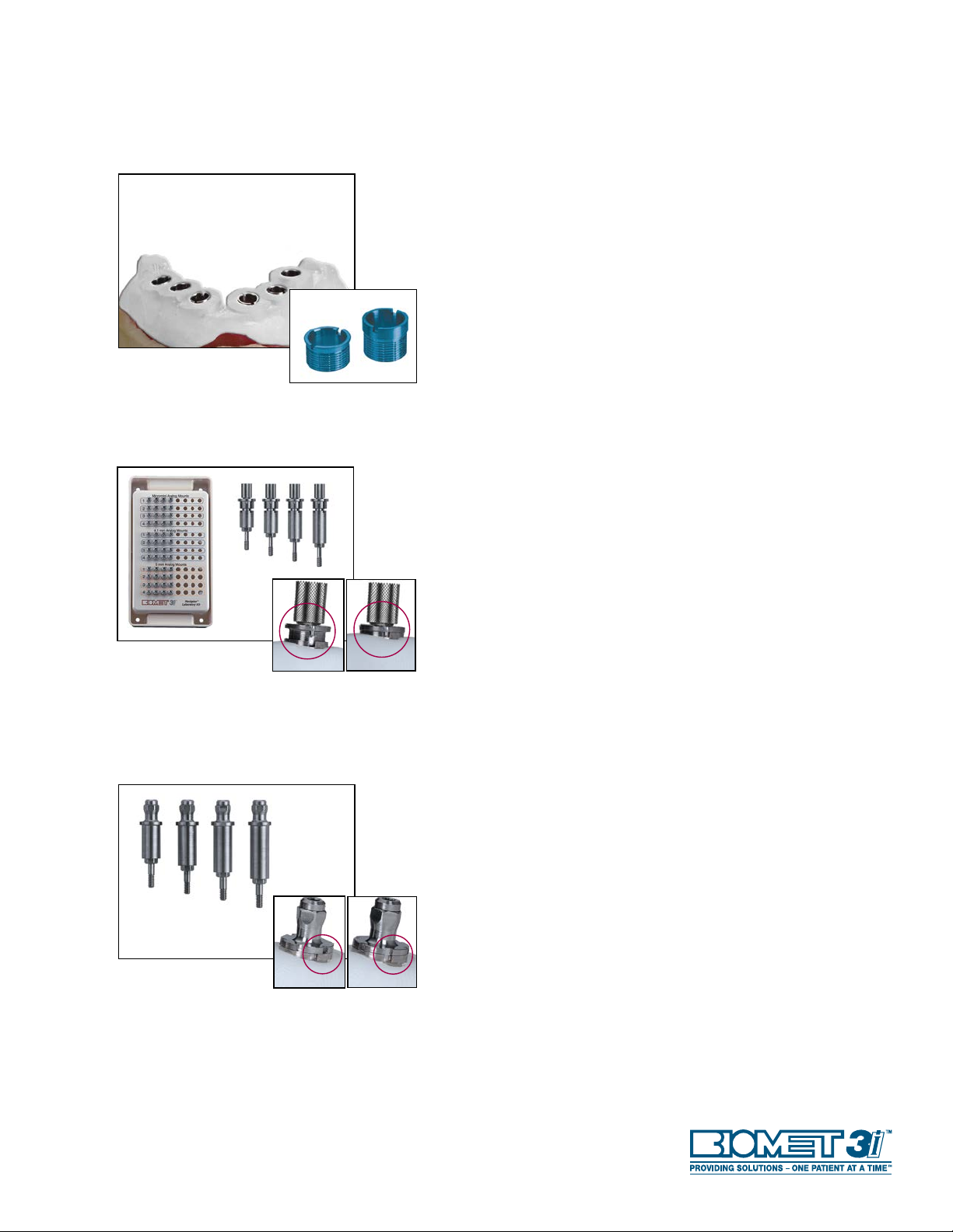
IMPLANT ANALOG MOUNTS
The Parallel Walled Navigator®Laboratory Kit is comprised
of Implant Analog Mounts used through the Master Tubes in
the surgical guide to position implant analogs into a cast. The
laboratory kit, like the surgical kit, contains twelve unique mounts
with the Certain®Connection and these mounts are available in
three diameters (3.4, 4.1 and 5mm) and four lengths identified
as (1), (2), (3), and (4). Because a specific Analog Mount may be
required multiple times, four complete sets of Analog Mounts are
available in the kit for a total of 48 Analog Mounts. The Analog
Mounts feature a mechanical-locking system to hold the implant
analog in place (vertically, laterally and rotationally) within the
Master Tube. A peg on the side of the Analog Mounts is aligned
with one of the slots on the Master Tube to ensure accurate
transfer of the hex orientation from the pre-operative master cast
to the mouth.
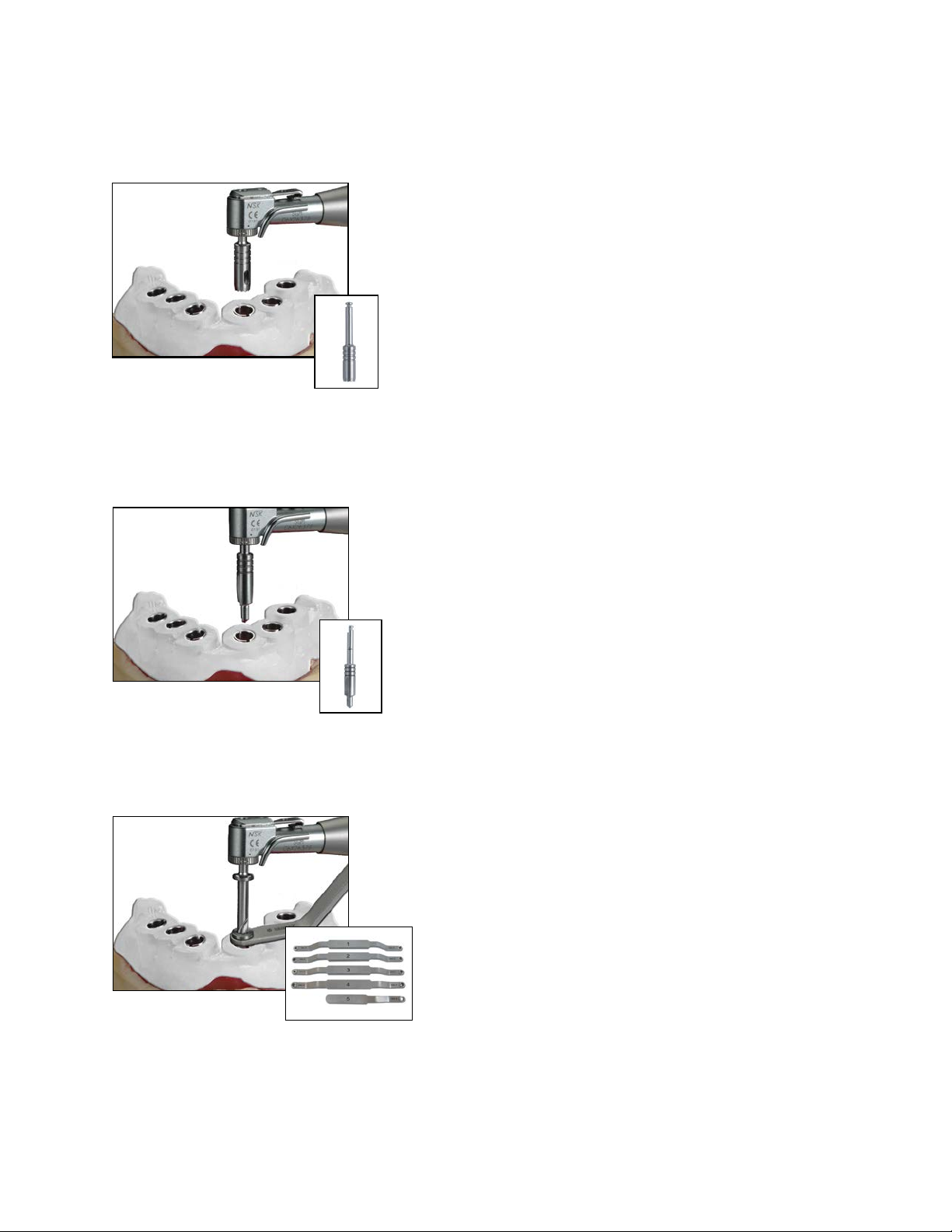
SURGICAL KIT COMPONENTS
IMPLANT MOUNTS
Implant Mounts are used through the Master Tubes in the surgical
guide to place implants. The Implant Mounts have the Certain
Connection and are available in three diameters (3.4, 4.1 and
5mm) and four lengths identified as (1), (2), (3), and (4) for a
total of twelve unique Implant Mounts. Because a specific Implant
Mount may be required multiple times, five complete sets of
Implant Mounts are available in the kit for a total of 60 Implant
Mounts. Implant Mounts are depth specific with a flange for a
depth stop. A “spline” feature on the flange can be used as a visual
reference during implant placement to orient the hex connection
of the implant. The cutouts on the flange are aligned with the
slots on the Master Tube to ensure accurate transfer of the hex
orientation from the pre-operative master cast to the mouth.
7
Instrumentation Overview (continued)
TISSUE PUNCHES
The Tissue Punches are used through the Master Tubes in the
surgical guide to remove soft tissue for flapless surgery. The
Tissue Punches are available in two diameters (4 and 5mm) and
one length and contain depth markings of (1), (2), (3) and the
top of the Tissue Punch (4) to correspond with the surgical plan
(protocols) for use during surgery.
The recommended drill speed is 300rpm.
STARTER DRILLS
The Starter Drills are used through the Master Tubes in the
surgical guide to perforate the cortical plate, create a 2mm pilot
and countersink the osteotomy. The Starter Drills are available in
five diameters (3.4, 3/4, 4, 4/5 and 5mm) to countersink different
implant collar shapes. These contain depth markings of (1), (2),
(3) and the top of the Starter Drill body (4) to correspond with
the surgical plan (protocols) for use during surgery.
The recommended drill speed is 1200 - 1500rpm.
DRILL POSITIONING HANDLES
The handles contain drill guide tubes that are placed within the
Master Tubes of the surgical guide to guide and stop the Twist
Drills at a specific predetermined depth for preparation of the
osteotomy. There are five handles [handles (1) and (2) for use
with 4mm Master Tubes and handles (3), (4) and (5) for use
with 5mm Master Tubes]. These contain drill guide tubes to
accommodate the various drill diameters (2, 2.75, 3, 3.25, 3.85
and 4.25mm).

8
Instrumentation Overview (continued)
TWIST DRILLS
The Twist Drills are used to prepare the osteotomy for implant
placement. Once the surgical guide is in place, the Drill Positioning
Handles with drill guide tubes are inserted into the Master Tubes of the
surgical guide. The Twist Drills are inserted through these guide tubes.
The drills are depth-specific with no depth lines and contain flanges
to stop the drills when these make contact with the drill guide tube
component of the Drill Positioning Handles. Twist Drills are available in
six diameters (2, 2.75, 3, 3.25, 3.85 and 4.25mm) to allow surgeons
to appropriately size osteotomies based on observed bone densities,
clinical preference and multiple lengths (A, B, C, D, E).
The recommended drill speed is 1200 - 1500rpm.
The drills included in the surgical kit will accommodate 90% of all
possible scenarios. Special drills required for the remaining 10% have
been left out to simplify the surgical kit. In these special cases, Y or
Z drills may be prescribed by the surgical plan. These drills may be
purchased separately as needed.
NOTE: Drill lengths do not necessarily correspond to implant lengths;
rather these are dictated by the surgical plan (protocols) based on the
prolongation (distance between the position of the Master Tubes and
implant seating surface).
BONE TAPS
Bone Taps are used through the Master Tubes in the surgical guide to
thread a 5.5mm section of the osteotomy prior to implant placement.
The Bone Taps are available in four diameters (3.25, 4, 4/5 and 5mm)
and one length. These contain depth markings (1), (2), (3) and at (4) the
Bone Tap body has a depth stop. These markings correspond with the
surgical plan (protocols) for use during surgery.
The recommended drill speed is 15 - 20rpm.
IMPLANT STAGING
The Parallel Walled Navigator®Surgical Kit contains eight implant holder
slots to receive the inner packaging of Implants, similar
to existing surgical kits. Implants will be manually
pre-mounted here in preparation for placement.
BONE PROFILERS
Handheld Bone Profilers are available to manually remove crestal bone
for proper abutment seating after the surgical guide is removed for 3.4,
4 and 5mm implants.
MISCELLANEOUS TOOLS
Miscellaneous standard drivers and ratchets are included in the system
to place BIOMET 3i Implants. These tools include the following:
PHD02N, RASH3N, MDR10, CW100, WR150 and RE100.

9
Surgical Plan Overview
Tooth number/
Implant position
Indicates 4mm diameter
Tissue Punch
Indicates drill diameter 2, length
(B) to be used with
Handle 3 Indicates 4mm diameter
Bone Tap
Indicates 3mm hand
held Bone Profiler
Indicates 4mm Analog Mount with a
(1) depth
Indicates 4mm Implant Mount
with a (3) depth
Indicates 4mm diameter
Starter Drill
Specifies preparation depth for Tissue
Punch, Starter Drill and Bone Taps with a
depth of (2)*
(4)
(3)
(2)*
(1)
The surgical plan specifies the depth line for instruments
that pass directly through the surgical guide Master Tubes
including the Tissue Punch, Starter Drill and Bone Taps.
These instruments have landmarks referenced as (1), (2),
(3) and (4) that indicate the proper depth to which these
instruments should be used through the Master Tubes
(Figure 1). There are three lines on each instrument; the
first line represents depth line (1), while the top of the
instrument represents depth line (4). The instruments
pass through the Master Tube until the center of the
specified line on the instrument reaches the top of the
Master Tube (Figure 2).
The depth lines also determine what Implant Mount and
Implant Analog Mount must be used. These are labeled
by diameter and length. Therefore a 4mm implant that
has a 3mm depth line will be specified as a 4(3).
Figure 1
Figure 2
The Parallel Walled Navigator®System For Guided
Surgery works in conjunction with the surgical plan,
which is provided by the CT planning software
company. Each surgical plan is case-specific to provide
direction regarding the instrumentation that will be used
for each implant site.

10
Planning:
• Be sure the CT scanning appliance fits and is seated
completely in the mouth before the scan is performed.
Failure to confirm a stable fit of the scanning appliance
may result in a poorly fitting surgical guide affecting the
outcome of the procedure.
• Refer to the surgical guide manufacturer for specific
instructions on how to mask anatomical structures and
plan for fixation of the surgical guide.
• Download the most recent version of planning software
including implant libraries.
• Implants currently compatible with the Navigator®
System Include:
• Certain®Parallel Walled 3.25, 4 & 5mm Implants
• OSSEOTITE XP®4/5mm Implants
• PREVAIL®3/4/3, 4/5/4 and straight PREVAIL
4/3 and 5/4mm Implants.
• Height of the master cylinder above the implant platform
is variable (7.5, 9, 10.5, 12mm) and determined by the
surgical guide manufacturer.
• If planning a cement-retained full arch case, consider
implant sites with the greatest potential for stability in
order to screw-retain these locations in combination
with cement retaining others based on:
• Bone density readings (in Hounsfield Units) from
CT Scan
• Potential implant length and position relative to
the restoration
Preparation:
• Inspect the surgical guide for imperfections and reinforce
potential weak areas of the surgical guide with acrylic.
• Try-in the Drill Positioning Handles in case the guide may
need adjustments to allow the Drill Positioning Handles
to fully seat.
• Clear the Master Tubes of any material remaining from
the surgical guide manufacturer.
• Score the Master Tube notch position on the surgical
guide to record the hex-orientation landmarks (Figure 1).
• Preparation of a master cast may be advised to confirm
the planned position and restorative considerations of
implants prior to surgery.
• Review the CT scan data for bone density to anticipate
areas of poor bone quality and areas where implant
stability may be compromised. During use, surgical
guides provide little tactile confirmation of bone density.
Clinical Use:
• For flapless cases, use a Tissue Punch prior to fixation of
the Surgical Guide. Remove the Surgical Guide and the
tissue plugs. Then, replace and fixate the Surgical Guide.
• All instrumentation should be advanced as far as possible
through the Master Tube(s) or the Drill Positioning
Handles and into the osteotomy prior to activation.
This will limit the possibility of damaging either the
instruments or the tube(s) (Figure 2).
Tips And Techniques
Figure 1
Figure 2

11
Tips And Techniques (Cont’d)
Figure 3
• Use copious irrigation on instruments prior to and during use to
provide lubrication and cooling when passing through the Master
Tube(s) and/or Drill Positioning Handle(s). Irrigate and suction the
osteotomy and tubes to remove debris between each step of the
Surgical Plan and prior to implant placement.
• Undersize the osteotomy to increase likelihood of initial implant
stability (ie. when planning for a 4mm implant use 3mm as
final Twist Drill; 5mm implant use 3.85mm as final Twist Drill.
If necessary, increase the diameter of the final Twist Drill
appropriately).
• Avoid applying lateral force on the instrumentation during use, as
this may cause damage or premature wear.
• When using the Implant Mounts and Bone Taps, progress the
instruments until the instrument flange contacts the Master Tube.
It is recommended to use the WR150 Ratchet Wrench
with extension for final rotations of these instruments.
Once seated, do not continue to rotate these instruments as this
can cause damage to the instrumentation or osteotomy (Figure 3).
• The Implant Mounts must be fully engaged within the implant
prior to tightening the Implant Mount Screw.
• Sequence the placement of implants in an alternating cross
arch pattern, moving from one side to the other so as to not
compress soft-tissue. For cases requiring more than
two (2) implants, removal of the subsequent Implant
Mounts immediately following implant placement will
reduce divergent forces on the Surgical Guide.
• When removing Implant Mounts, remove along the path of
insertion and avoid applying lateral force. A slight counter-
clockwise torque applied to the Implant Mount with the CW100
may assist with Implant Mount removal.
• Use Bone Profilers prior to placing abutments of any type. Use
an oversized profiler when placing angulated abutments.

12
A key benefit of using the Navigator®
System For Guided Surgery is the option to use a CT
surgical guide to create a preoperative master cast and
a fixed provisional restoration in the laboratory prior to
the day of surgery. This may allow the clinician to insert
a provisional restoration immediately following implant
placement using the surgical guide and provides the patient
with aesthetic and functional teeth the same day.
Pages 13-28 in this manual are designed to guide surgeons,
restorative clinicians and laboratory technicians through
the process of fabricating a preoperative master cast
and a provisional restoration for insertion following the
placement of BIOMET 3i Implants using the Parallel Walled
Navigator System For Guided Surgery. The CT software
company may also offer the option of fabricating a stereo
lithographic model for use in creating a master cast.
The provisional may be fabricated using a variety of
BIOMET 3i Provisional Components. These components
and manual guidelines were developed to provide an
easy to use way to deliver an accurately fitting provisional
restoration on the day of surgery regardless of potential
error from CT scan data, cast fabrication or implant
placement. When selecting the provisional component
to use, it is important to identify the type of definitive
prosthesis and the abutment system that will be used to
create it. The chart below includes recommendations that
a clinician may want to consider for provisional component
selection dependent upon the type of definitive restoration
planned.
Immediate Provisionalization Option
Provisional Component Seating Platform Provisional Restoration Final Restoration
PreFormance®Posts Direct To Implant Cement-Retained Cement-Retained Or
Screw-Retained
PreFormance Temporary
Cylinders Direct To Implant Screw-Retained Cement-Retained Or
Screw-Retained
Provide®Temporary
Cylinders
Abutment Level
(For Provide Abutments Only) Cement-Retained Cement-Retained
QuickBridge®Provisional
Restoration Components
Abutment Level
(for Conical Abutments Only) Cement-Retained Screw-Retained
13
Fabrication Of A New Denture Or Partial
Denture And CT Scanning Appliance
1. CLINICIAN
Make impressions of the maxillary and mandibular arches.
2. LABORATORY
Pour the maxillary and mandibular impressions in die stone.
Fabricate baseplate(s) and wax occlusal rim(s) on the cast(s).
3. CLINICIAN
Place the wax occlusal rim(s) in the mouth, contour appropriately
and make an interocclusal registration.
4. LABORATORY
Articulate the maxillary and mandibular casts using the interocclusal
registration. Set denture teeth on the baseplate(s) and wax for try in.

14
Fabrication Of A New Denture Or Partial
Denture And CT Scanning Appliance (continued)
5. CLINICIAN
Place the wax try-in(s) in the mouth. Verify the occlusion, aesthetics
and phonetics. Make any adjustments necessary. If major adjust-
ments are necessary, make a new interocclusal registration and
return to the laboratory for a new set-up and wax try-in.
6. LABORATORY
Wax the denture for the arch in which implants will be placed for
processing, and flask it. Separate the flask, and boil away the wax.
Process, finish and polish the denture. Using a denture duplication
flask, mix the duplication material and place it into one side of the
flask. Place the patient’s existing denture into the material with the
soft-tissue side down. Allow the duplication material to set per the
manufacturer’s instructions. Apply a separator to the surface. Mix the
duplication material and place it into the other side of the flask and
close the flask over the denture. Allow the duplication material to
set. Separate the flask and remove the denture.
7. Create a mixture of 30% barium sulfate and cold-cure acrylic resin.
Pour the mixture into the tooth areas only. Allow the acrylic resin
to set per the manufacturer’s instructions. Create a mixture of 10%
barium sulfate and cold-cure acrylic resin. Pour the mixture into the
flask. Close the flask tightly. Allow the acrylic resin to set.
8. Remove the CT scanning appliance from the flask, finish and polish.
Place the appliance on the cast. Place the cast on the articulator and
make an interocclusal registration. The scanning appliance is returned
to the clinician for the CT scan and the occlusal registration is set
aside for later use.

15
Fabrication Of CT Scanning Appliance Using An
Existing Denture (continued)
1. CLINICIAN OR LABORATORY
Using a denture duplication flask, mix the duplication material
and place it into one side of the flask. Place the patient’s existing
denture into the material with the soft-tissue side down. Allow
the duplication material to set per the manufacturer’s instructions.
Apply a separator to the surface. Verify the occlusion duplication
material and place it into the other side of the flask and close
the flask over the denture. Allow the duplication material to set.
Separate the flask and remove the denture.
2. Create a mixture of 30% barium sulfate and cold-cure acrylic resin.
Pour the mixture into the tooth areas only. Allow the acrylic resin
to set per the manufacturer’s instructions. Create a mixture of
10% barium sulfate and cold-cure acrylic resin. Pour the mixture
into the flask. Close the flask tightly. Allow the acrylic resin to set.
3. Remove the CT scanning appliance from the duplication flask, finish
and polish.
4. CLINICIAN
Place the CT scanning appliance in the mouth and equilibrate.
Make an interocclusal registration. Send the scanning appliance
with the patient for the CT scan and set aside the interocclusal
registration for later use.

16
1. LABORATORY
Select the proper diameter and length Analog Mounts for each
implant position following the instructions provided by the Surgical
Guide manufacturer. Place the Implant Analogs onto the Analog
Mounts, line up the hexes and thread the thumb screws into
these approximately two turns. Place the Analog Mount/Analog
assemblies through the Master Tubes, engage the rotational
positioning pin into the notch and tighten the thumb screws using
the Square Driver.
TIP: Over-tightening the Analog Mounts outside of the Master
Tubes may damage the Analog Mounts.
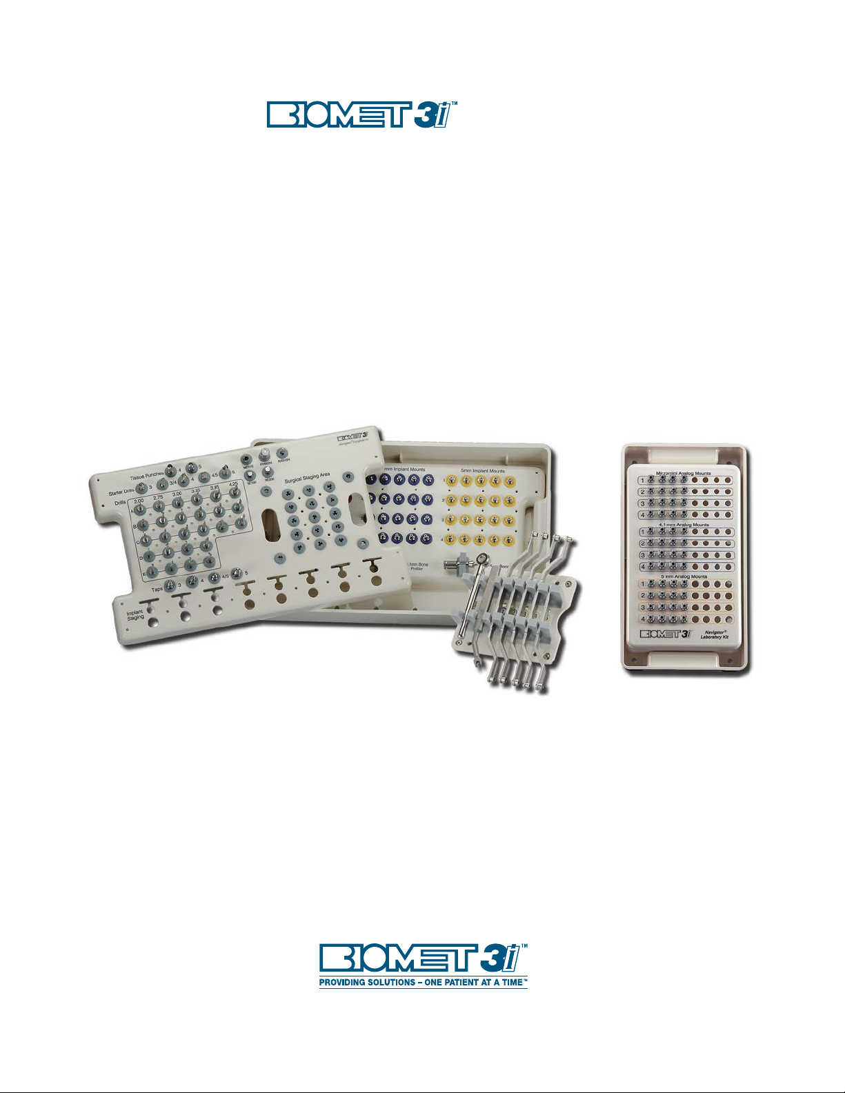
2. Bead and box the Surgical Guide using rope wax. Apply a stone
separator around the inside of the guide. Syringe soft-tissue
material around the analogs approximately 2mm apical from the
interface of the Analog Mount. Pour stone into the Surgical Guide
to create the master cast and allow it to set. Unscrew the thumb
screws and remove the Analog Mounts. Carefully separate the
Surgical Guide from the master cast.
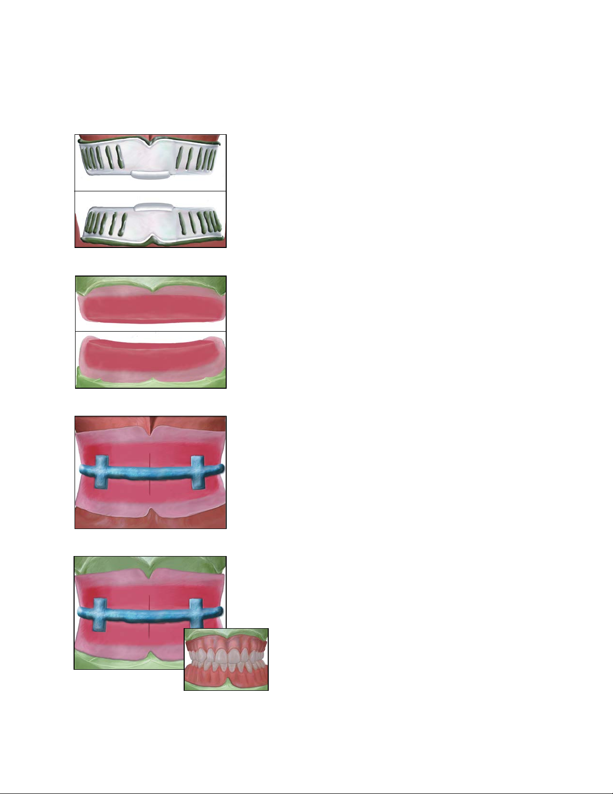
3. Place the scanning appliance on the master cast and verify the fit
and tooth position. Articulate the master cast with the opposing
cast using the scanning appliance and the interocclusal registration.
4. Make a vacuum formed template over the scanning appliance on
the cast. Remove the template and the scanning appliance and
separate those.
Continue on to step 5 (pages 22, 24 or 26) for abutment
selection and provisional restoration fabrication.
Pre-Surgical Fabrication Of An Edentulous
Fixed Provisional Restoration
Fabrication Of Master Cast, Articulation And Vacuum Formed Template

17
1. LABORATORY
Select the proper diameter and length Analog Mounts for each
implant position following the instructions provided by the Surgical
Guide manufacturer. Place the Implant Analogs onto the Analog
Mounts, line up the hexes and thread the thumb screws into these
approximately two turns. Place the Analog Mount/Analog assemblies
through the Master Tubes, engage the rotational positioning
notches and tighten the thumb screws using the Square Driver.
TIP: Over-tightening the Analog Mounts outside of the Master
Tubes may damage the Analog Mounts.
2. Mark the planned implant locations on the preoperative cast and
drill holes for each implant that is slightly larger in diameter than the
Implant Analogs. Do not drill through the guide. Insert the Implant
Analogs attached to the Surgical Guide into the holes, and seat the
guide onto the remaining teeth on the cast. Fixate the analogs in the
cast using stone or pattern resin. Unscrew the thumb screws and
remove these. Remove the Surgical Guide from the master cast.
3. If a scanning appliance was fabricated on the cast, place it on the
master cast and verify the fit and tooth position. Articulate the
master cast with the opposing cast using the occlusal registration.
4. Make a vacuum formed template over the scanning appliance
or diagnostic setup on the cast. Remove the template and the
scanning appliance or setup and separate those.
Continue on to step 5 (pages 18 or 20) for abutment
selection and provisional restoration fabrication.
Pre-Surgical Fabrication Of A Partially Edentulous Fixed
Provisional Restoration
Fabrication Of Master Cast, Articulation And Vacuum Formed Template
Table of contents


