Biosan MM-1000 User manual


2
Contents
1. About this edition of user instructions.......................................................................2
2. Safety precautions ...................................................................................................3
3. General information..................................................................................................4
4. Getting started..........................................................................................................5
5. Operation .................................................................................................................6
6. Program setting........................................................................................................7
7. Specifications...........................................................................................................9
8. Care and maintenance...........................................................................................10
9. Warranty.................................................................................................................10
10. EU Declaration of conformity..................................................................................11
1. About this edition of user instructions
The manual applies to following version of overhead stirrer:
MM-1000 Multi Mixer version V.2AW

3
2. Safety precautions
Caution! Make sure you have fully read and understood the present Manual
before using the equipment. Please pay special attention to sections
marked by this symbol.
GENERAL SAFETY
Use only as specified in the operating manual provided
Save the unit from shocks and falling.
Store and transport the unit at ambient temperatures between -20°C and +60°C and
maximum relative humidity of 80%.
After transportation or storage and before connecting it to the electric circuit, keep the
unit under room temperature for 2-3 hrs.
Use only original parts and accessories, provided by manufacturer for this product.
Before using any cleaning or decontamination methods except those recommended
by the manufacturer, check with the manufacturer that the proposed method will not
damage the equipment.
Do not make modifications in design of the unit.
ELECTRICAL SAFETY
Connect only to the mains with voltage corresponding to that on the serial number
label.
Use only the external power supply provided with this product.
Ensure that the power plug is easily accessible during use.
Disconnect the unit from the mains before moving.
If liquid penetrates into the unit, disconnect it from the mains and have it checked by
a repair and maintenance technician.
Do not operate the unit in premises where condensation can form. Operating
conditions of the unit are defined in the Specifications section.
DURING OPERATION
Do not operate the unit in environments with aggressive or explosive chemical
mixtures. Please contact manufacturer for possible operation of the unit in specific
atmospheres.
Do not operate the unit if it is faulty or has been installed incorrectly.
Do not use outside laboratory rooms.
Do not leave the operating unit unattended.
BIOLOGICAL SAFETY
It is the user’s responsibility to carry out appropriate decontamination if hazardous
material is spilt on or penetrates into the equipment.
4
3. General information
MM-1000 Overhead stirrer Multi Mixer is designed for mixing solutions of different
viscosity.
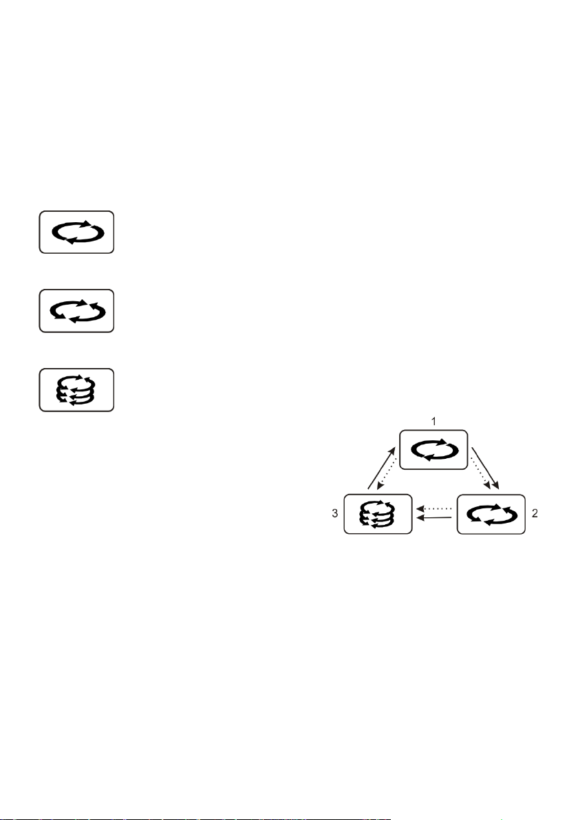
Multi Mixer MM-1000 provides three types of motion: 1) rotational motion, 2)
reciprocal motion and 3) vibro motion, according to the microprocessor protocol. The
protocol enables making not only programs that include mixing motion of one particular type,
but also programs that alternate mixing motions of different types cyclically.
Rotational motion
Simple even rotation with an option of shifting direction (clockwise/counter
clockwise) after set time. The speed adjustment range is from 40 to 1000
rpm with 10 rpm increment. The motion time can be set in 0 to 250 s range
or non-stop.
Reciprocal motion
Reciprocal motion direction changing, limited by the turning angle. The
turning angle adjustment range is from 0° to 360° with 30° increment. The
speed is the same as set for rotational motion. The motion time can be set in
0 to 250 s range or non-stop.
Vibro motion Intensive mixing at high speed with small adjustable turning angle. The
turning angle adjustment range is from 0° to 5° with 1° increment. The motion
time can be set in 0 to 5 s range or non-stop. Reciprocating and Vibro motion
types can be replaced by a pause.
These 3 motions are combined in a cycle
and can be used:
separately (only 1; 2; or 3);
in combinations by two;
all three in one cycle (fig. 1).
A timer with the working range from 1 min to
96 hr is used to control the total time of operation.
By combining the provided motion types a
researcher gets unlimited options for choosing the
mixing parameters.
Apart from the unique operation modes, MM-1000 Multi Mixer offers user-friendly
interface, which provides options not only for changing the program during the operation, but
also for simultaneous control over different steps of mixing protocol realisation.
The external power supply ensures the electrical safety of the device.
Figure 1. Innovative mixing cycle
5
4. Getting started
4.1. Unpacking. Remove packing materials carefully and retain them for future shipment
or storage of the unit. Examine the unit carefully for any damage incurred during
transit. The warranty does notcover in-transit damage.Warranty covers only the units
transported in the original package.
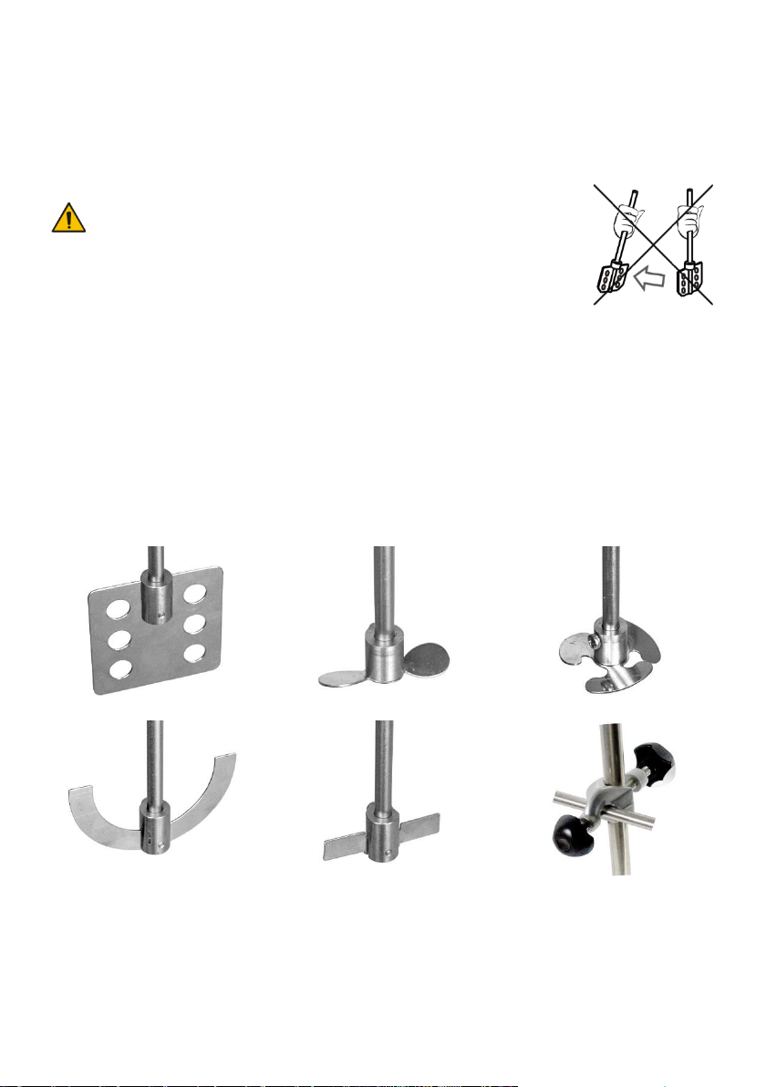
Caution! Do not apply excessive force on the clamping
chuck. When moving, hold the unit at the housing,
not at the clamping chuck.
4.2. Complete set. Package contents:
4.2.1. Standard set
- MM-1000 Overhead Stirrer...............................................................................1 pce.
- Rod for fixing on the support stand ..................................................................1 pce.
- External power supply .....................................................................................1 pce.
- Operating manual, declaration of conformity ..................................................1 copy
4.2.2. Optional accessories:
- MP-1 stirring element ............................................................................on request
- МР-2 stirring element ............................................................................on request
- МР-3 stirring element ............................................................................on request
- МA-1 stirring element ............................................................................on request
- МС-1 stirring element ............................................................................on request
- Double clamp ........................................................................................on request
- Support stand ...........................................................................................on request
6
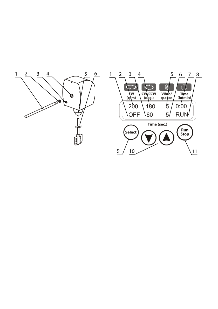
4.3. Setup.
- Place the unit on horizontal even working surface.
- Screw the nut (fig. 2/2) on the support stand (fig. 2/1);
- Screw in the support stand (fig. 2/1) in the opening (fig. 2/4) on the rear side of the
Multi Mixer. Fasten the fixing rod by tightening the nut (fig. 2/2) clockwise;
- Fasten the unit on the stand with the double clamp;
- Fasten the stirring element axle (fig. 2/6) in the clamping chuck (fig. 2/5) without
applying excessive sideways force;
- Plug the external power supply into the socket at the rear side of the unit (fig. 2/3);
- Remove the protective film from the display.
Figure 2. Assembly Figure 3. Control panel
5. Operation
5.1. Connect the external power supply to the mains.
5.2. Dip the stirrer inside the vessel with the liquid being mixed. The stirring element
should be completely dipped into the liquid.
5.3. Turn on the red power switch on the front panel. Display shows following indications:
Upper line: rotation speed (fig. 3/2), reciprocation angle (fig. 3/4), vibration angle (fig.
3/5), overall timer (fig. 3/7);
Lower line: rotation, reciprocation and vibro timers (fig. 3/1, 3/3 and 3/6), status
(STOP, fig. 3/8).
5.4. Set the required program and operation time (see section 6. Program setting).
5.5. Press the Run Stop key (fig. 3/11) to start the program.
5.6. The stirrer motion will begin and the corresponding indication, RUN (fig. 3/8) and the
changing time values (fig. 3/1, 3/3, 3/6 and 3/7) are be shown on the display.
5.7. If the overall operation time is not set and the Time indicator (fig. 3/7) shows 0:00,
pressing the Run Stop key will start continuous operation of the unit until the Run
Stop key is pressed again.

7
5.8. If the operation time is set then the unit will stop after the set time interval elapses.
Flashing indication STOP (fig. 3/8) is shown on the display and a repeating sound
signal for the end of operation is heard. Press the Run Stop key to stop the signal.
5.9. Press the Run Stop key to repeat the preset program.
5.10. The unit can be stopped at any time during operation before the set time elapses if
necessary by pressing the Run Stop key. Pressing the Run Stop key again will start
the program from the beginning (timer will be restarted).
5.11. After finishing the operation, turn off the power switch.
5.12. Unplug the external power supply from the mains.
6. Program setting
6.1. The program consists of cycles. Each cycle includes motions of three different types
(rotational, reciprocating and vibro) set one after another with the duration from 0 to
250 seconds for rotational and reciprocal motion types and from 0 to 5 seconds for
vibro motion.
6.2. Changing parameters. Press the Select key (fig. 3/9) to choose the parameter to
change, each consecutive press activates the next parameter in cycle. Active
parameter is flashing. Use the ▲ and ▼ keys (fig. 3/10) to set the necessary value.
Pressing the key for more than 2 s increases value changing speed.
6.3. All parameters except overall timer can also be changed during the operation. Unit
automatically saves and applies changes to the current work program.
6.4. Following parameters are available: rotation and reciprocation speed, reciprocation
and vibro turning angle, time for each motion type and overall operation timer.
6.5. Skip a motion. If the time for a type of motion is set to zero (indication OFF), this
type of motion will be skipped in the cycle.
6.6. Pause. If the turning angle for reciprocating or vibro motions is set to zero (indication
0), unit will interpret this as a pause. The stirring element will not move in this mode
during the operation and the overall timer will be counted down.
6.7. The overall timer (fig. 3/7) is used to control the operation time. The timer can be set
for the period from 1 min to 96 hours (increment 1 min). If the timer is set to 00:00,
unit operates non-stop, see 5.7.
6.8. Table 1 shows possible motion combinations in the cycle.
Table 1. Motion type combinations
#
Rotational
Reciprocal
Vibro
#
Rotational
Reciprocal
Vibro
1
ON
ON
ON
8
ON
ON
OFF
2
ON
OFF
ON
9
ON
ON
Pause
3
ON
Pause
ON
10
OFF
ON
ON
4
ON
OFF
OFF
11
OFF
Pause
ON
5
ON
Pause
OFF
12
OFF
ON
Pause
6
ON
OFF
Pause
13
OFF
OFF
ON
7
ON
Pause
Pause
14
OFF
ON
OFF
6.9. Further examples illustrate program setting for both separate motions and their
combinations in the cycle.

8
6.9.1. Rotational motion. Set the speed (40-1000 rpm, fig. 3/A) and time (1-250 s, fig. 3/B)
of rotational motion. Turn off reciprocal andvibro motions by setting their motion times
to zero (indications OFF, fig. 3/C and 3/D).
MM-1000 is programmed to change the direction of rotation when the motion timer is
restarted, i.e. if the rotation time is set to 30 s, then the direction is changed every 30
s as shown on figure 4, where positive RPM is clockwise motion and negative -
counter clockwise.
Figure 3. Figure 4.
6.9.2. Rotational + Reciprocal + Vibro motions. Set the speed (40-1000 rpm, fig. 5/A)
and time (1-250 s, fig. 5/D) of rotational motion. Set the angle (30-360º, fig. 5/B) and
time (1-250 s, fig. 5/E) of reciprocal motion. Reciprocal and rotational motions have
the same speed. Set the turning angle (1-5º, fig. 5/C) and time (1-5 s, fig. 5/F) for
vibro motion. Graph in figure 6 shows motion in this mode.
Figure 5. Figure 6.
6.9.3. Rotational + Reciprocal motions + Pause. Set the speed (40-1000 rpm, fig. 7/A)
and time (1-250 s, fig. 7/D) of rotational motion. Set the angle (30-360º, fig. 7/B) and
time (1-250 s, fig. 7/E) of reciprocal motion. Reciprocal and rotational motions have
the same speed. Set the turning angle of vibro motion to zero (fig. 7/C). Set the time
of vibro motion (1-5 s, fig. 7/F) - this is the duration of pause. Graph in figure 8 shows
motion in this mode.
Figure 7. Figure 8.
6.9.4. Vibro motion + Pause. Turn off Rotational motion by setting time of rotational motion
to zero (OFF, fig. 9/C). Set the turning angle of reciprocal motion to zero (fig. 9/A)
and set the time for reciprocal motion (1-250 s, fig. 9/D) - thisis the duration of pause.
Set the turning angle (1-5º, fig. 9/B) and time (1-5 s, fig. 9/E) for vibro motion. Graph
in figure 10 shows motion in this mode.
Figure 9. Figure 10.

9
7. Specifications
The unit is designed for operation in cold rooms, incubators (except CO2 incubators)
and closed laboratory rooms at ambient temperature from +4°C to +40°C in a non-
condensing atmosphere and maximum relative humidity 80% for temperatures up to 31°C
decreasing linearly to 50% relative humidity at 40°C.
Biosan is committed to a continuous programme of improvement and reserves the
right to alter design and specifications of the equipment without additional notice.
7.1. Rotational motion
7.1.1. Speed range ........................................................ 40 - 1000 rpm (increment 10 rpm)
7.1.2. Timer ...........................................................................................................0 - 250 s
7.2. Reciprocal motion
7.2.1. Turning angle .................................................................... 0º - 360° (increment 30º)
7.2.2. Timer ...........................................................................................................0 - 250 s
7.3. Vibrating motion
7.3.1. Turning angle .......................................................................... 0º - 5° (increment 1º)
7.3.2. Timer ...............................................................................................................0 - 5 s
7.4. General timer of operation ........................1 min - 96 h (increment 1 min) / non-stop
7.5. Maximal stirring volume (water) ..........................................................................20 l
7.6. Maximal stirring liquid viscosity.............................................................. 1000 mPa·s
7.7. Dimensions (w/out rod) ............................................................ 140 x 135 x 250 mm
7.8. Rod for fixing on the support stand, diam. x length .................... Ø 12 mm x 260 mm
7.9. Stirrer shaft ...................................................................................................Ø 8 mm
7.10. Stirrer material....................................................................Stainless steel (AISI 304)
7.11. Input current/power consumption.............................................12 V, 700 mA / 8.4 W
7.12. External power supply...................... input AC 100-240 V 50/60 Hz, output DC 12 V
7.13. Weight
1
.............................................................................................................2.4 kg
Optional
accessories
Description
Catalogue
number
MP-1
Paddle stirring element, 378x(70x70)x8 mm
BS-010306-AK
MP-2
Propeller stirring element, 2 blades 326x55x8 mm
BS-010306-BK
MP-3
Propeller stirring element 3 blades 325x50x8 mm
BS-010306-CK
MA-1
Anchor stirring element, 332x90x8 mm
BS-010306-DK
MC-1
Centrifugal stirring element, 358x60(110)x8 mm
BS-010306-EK
Double clamp
For unit fixing
VELA00001300
Support stand
For unit fixing, 400x300x870 mm
VELA00001301
1
Accurate within ±10%

10
8. Care and maintenance
8.1. If the unit requires maintenance, disconnect the unit from the mains and contact
Biosan or your local Biosan representative.
8.2. All maintenance and repair operations must be performed only by qualified and
specially trained personnel.
8.3. Standard ethanol (75%) or other cleaning agents recommended for cleaning of
laboratory equipment can be used for cleaning and decontamination of the unit.
8.3.1. Stirrers are made of stainless steel (AISI 304). After cleaning, rinse with water and
dry the stirrers. Avoid prolonged contact with rusted metals.
9. Warranty
9.1. The Manufacturer guarantees the compliance of the unit with the requirements of
Specifications, provided the Customer follows the operation, storage and
transportation instructions.
9.2. The warranted service life of the unit from the date of its delivery to the Customer is
24 months. For extended warranty, see 9.5.
9.3. Warranty covers only the units transported in the original package.
9.4. If any manufacturing defects are discovered by the Customer, an unsatisfactory
equipment report shall be compiled, certified and sent to the local distributor address.
To obtain the claim form, visit section Technical support on our website at link below.
9.5. Extended warranty. For MM-1000, the Basic Plus class model, extended warranty is
a paid service. Contact your local Biosan representative or our service department
through the Technical support section on our website at the link below.
9.6. Description of the classes of our products is available in the Product class
description section on our website at the link below.
Technical support
Product class description
biosan.lv/en/support
biosan.lv/classes-en
9.7. The following information will be required in the event that warranty or post-warranty
service comes necessary. Complete the table below and retain for your records.
Model
MM-1000 Multi Mixer, overhead stirrer
Serial number
Date of sale

11
10. EU Declaration of conformity
Unit type Overhead stirrer
Models MM-1000
Serial number 14 digits styled XXXXXXYYMMZZZZ, where XXXXXX is
model code, YY and MM –year and month of production,
ZZZZ –unit number.
Manufacturer SIA BIOSAN
Latvia, LV-1067, Riga, Ratsupites str. 7/2
Applicable Directives EMC Directive 2014/30/EU
LVD Directive 2014/35/EU
RoHS2 2011/65/EU
WEEE 2012/19/EU
Applicable Standards LVS EN 61326-1: 2013
Electrical equipment for measurement, control and
laboratory use. EMC requirements. General requirements.
LVS EN 61010-1: 2011
Safety requirements for electrical equipment for
measurement, control, and laboratory use. General
requirements.
LVS EN 61010-2-051: 2015
Particular requirements for laboratory equipment for mixing
and stirring.
We declare that this product conforms to the requirements of the above Directives
____________________ ____________________
Signature Signature
Svetlana Bankovska Aleksandr Shevchik
Managing director Engineer of R&D
____________________ ____________________
Date Date

Biosan SIA
Ratsupites 7, build.2, Riga, LV-1067, Latvia
Phone: +371 67426137 Fax: +371 67428101
http://www.biosan.lv
Edition 2.03 –August 2017
Table of contents


 owner's manual")


