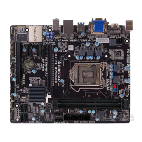
Biostar BIMX-100 User manual

FCC Informaon and Copyright
This equipment has been tested and found to comply with the limits of a Class B digital device,
pursuant to Part 15 of the FCC Rules. These limits are designed to provide reasonable protecon
against harmful interference in a residenal installaon. This equipment generates, uses, and can
radiate radio frequency energy and, if not installed and used in accordance with the instrucons,
may cause harmful interference to radio communicaons. There is no guarantee that interference
will not occur in a parcular installaon.
The vendor makes no representaons or warranes with respect to the contents here and
specially disclaims any implied warranes of merchantability or tness for any purpose. Further
the vendor reserves the right to revise this publicaon and to make changes to the contents here
without obligaon to nofy any party beforehand.
Duplicaon of this publicaon, in part or in whole, is not allowed without rst obtaining the
vendor’s approval in wring.
The content of this user’s manual is subject to be changed without noce and we will not be
responsible for any mistakes found in this user’s manual. All the brand and product names are
trademarks of their respecve companies.
Dichiarazione di conformità sinteca
Ai sensi dell’art. 2 comma 3 del D.M. 275 del
30/10/2002
Si dichiara che questo prodoo è conforme
alle normave vigen e soddisfa i requisi
essenziali richies dalle direve
2004/108/CE, 2006/95/CE e 1999/05/CE
quando ad esso applicabili
Short Declaraon of conformity
We declare this product is complying with the
laws in force and meeng all the essenal
requirements as specied by the direcves
2004/108/CE, 2006/95/CE and 1999/05/CE
whenever these laws may be applied

2 | Table Of Contents
Table Of Contents
FCC Informaon and Copyright ������������������������������������������������������������������������������� 1
Chapter 1: Introducon������������������������������������������������������������������������������������������� 3
1.1 Before You Start.................................................................................................................. 3
1.2 Package Checklist................................................................................................................ 3
1.3 Specicaons...................................................................................................................... 4
Chapter 2: Hardware installaon����������������������������������������������������������������������������� 7
2.1 Central Processing Unit (CPU)............................................................................................. 7
2.2 Connect Cooling Fans ......................................................................................................... 7
2.3 Installing System Memory (1.35V only) .............................................................................. 7
2.4 Power Supply ...................................................................................................................... 8
2.5 Jumpers / Headers / Connectors ...................................................................................... 10
2.6 Expansion Slots ................................................................................................................. 15
Chapter 3: BIOS Setup������������������������������������������������������������������������������������������� 16
3.1 Main Menu ....................................................................................................................... 17
3.2 Advanced Menu................................................................................................................ 18
3.3 Chipset Menu.................................................................................................................... 32
3.4 Security Menu................................................................................................................... 38
3.5 Boot Menu........................................................................................................................ 40
3.6 Exit Menu.......................................................................................................................... 41
Chapter 4: Useful help������������������������������������������������������������������������������������������� 42
4.1 Driver Installaon ............................................................................................................. 42
4.2 AMI BIOS Beep Code......................................................................................................... 43
4.3 AMI BIOS post code .......................................................................................................... 43
4.4 Troubleshoong................................................................................................................ 45

Chapter 1: Introducon | 3
BIMX-100/BIMX-200 User’s Manual
Chapter 1: Introducon
1�1 Before You Start
Thank you for choosing our product. Before you start installing the motherboard, please make
sure you follow the instrucons below:
• Prepare a dry and stable working environment with sucient lighng.
• Always disconnect the computer from power outlet before operaon.
• Before you take the motherboard out from an-stac bag, ground yourself properly
by touching any safely grounded appliance, or use grounded wrist strap to remove the
stac charge.
• Avoid touching the components on motherboard or the rear side of the board unless
necessary. Hold the board on the edge, do not try to bend or ex the board.
• Do not leave any unfastened small parts inside the case aer installaon. Loose parts
will cause short circuits which may damage the equipment.
• Keep the computer from dangerous area, such as heat source, humid air and water.
• The operang temperatures of the computer should be 0 to 45 degrees Celsius.
• To avoid injury, be careful of:
Sharp pins on headers and connectors
Rough edges and sharp corners on the chassis
Damage to wires that could cause a short circuit
1.2 Package Checklist
• Mini-ITX Mainboard x 1
• Fully Setup Driver DVD x 1
• I/O Bracket x 1
• SATA Cable x 1
Note
»
»The package contents may be dierent due to the sales region or models in which it was sold. For
more informaon about the standard package in your region, please contact your dealer or sales
representave.

4 | Chapter 1: Introducon
1�3 Specifications
CPU Intel® Celeron® Processor J1900 (2M Cache, up to 2.42 GHz)
* Co-lay with Intel® Celeron® Processor J1800
Graphic
Integrated Intel® HD Graphics series graphic engine
Graphics Frequency: Intel Graphics HD 688MHz-854MHz
Dual Display: D-Sub 15 Pin + LVDS dual channel 18-24Bits support by Realtek RT2136
Super I/O
FINTEK F81866AD
Provides the most commonly used legacy Super I/O funconality. 128pin type
Environment Control iniaves, H/W Monitor, Fan Speed Controller
Main Memory 1x SO-DIMM (204pin) slot, DDR3L 1333/1066 MHz, Max 8GB
Registered DIMM or ECC DIMM is not supported
SATA
Chipset built-in Serial ATA controller, 2x SATA ports
SATA Version 2.0 specicaon compliant, data transfer rates up to 3.0 Gb/s
*SATA2 Port co-lay with mSATA (PE1) socket
LAN
Realtek RTL 8111G
10 / 100 / 1000 Mb/s auto negoaon, Half / Full duplex capability
* Oponal LAN2
Sound Codec Realtek Codec ALC662, supports Line-out/Mic-in
Expansion Slots
BIMX-100 BIMX-200
1x full-size mPCIe socket (mSATA+USB2.0) 1x full-size mPCIe socket (mSATA)
1x half-size mPCIe socket (PCIe) 1x half-size mPCIe socket (PCIe+USB2.0)
1x SIM card socket (only for BIMX-100)
Back Panel I/O
1x PS2 for Keyboard
1x PS2 for Mouse
1x Printer Port
1x COM Port (co-lay with HDMI port)
1x VGA Port
1x LAN Port (LAN2 is oponal)
4x USB 2.0 Ports
1x Audio Connector
On Board Connectors
& Headers
SATA
2x SATA II up to 3Gb/s HDD connector
* SATA2 is shared with mSATA (PE1) slot
Display
1x 2*15 BOX header, LVDS connector support dual
channel LCD panel
1x 2*3 pins LCD power select jumper (3.3V/5V/12V)
1x 1*3 pins LCD backlight power select jumper
(5V/12V)
1x 1*3 pins LCD backlight control mode select
jumper (PWM/Voltage Level)
1x 1*8 pins LCD backlight inverter connector
Speaker
2x 1*2 pins for Amplier output ALC105 class D
3Wa/Channel Amplier
1x buzzer
Power
1x 4-Pin ATX Power connector DC+12V (BIMX-200)
1x 20-pin ATX Power connector (BIMX-200)
2x 1*4 pins for HDD power 5V
I/O
1x 2*5 pins, USB2.0 pin header support 2 USB
devices
1x 1*4 pins, USB2.0 pin header support 1 USB
device (oponal and shared with PE1/PE2 socket)
5x 2*5 pins COM2/3/4/5/6 ports, RS232
5x 0V/5V/12V select jumpers (COM2/3/4/5/6)
1x 2*5 pins header, digital IO support 4 in 4 out
1x 2*13 pins, parallel header for printer
1x 1*3 pins, system fan header
1x 1*4 pins, CPU fan header
1x 2*5 pins front panel as Power/Reset/HDD/LAN
header
1x 2*3 pins, RS232/422/485 jumper (COM1)
1x 1*3 pins, 0V/5V/12V select jumper (COM1)
Board Size 170 mm (W) x 170 mm (L), Mini-ITX
Operaon Temperature 0°C ~ 60°C
Storage Temperature -20°C ~ 80°C
Relave Humidity 10% ~ 90% (non-condensing)
Watchdog Timer Yes (65536 segments)
OS Support Windows 7, Windows 8.1, Windows 10*
Biostar reserves the right to add or remove support for any OS with or without noce.

Chapter 1: Introducon | 5
BIMX-100/BIMX-200 User’s Manual
1.4 Rear Panel Connectors
BIMX-100
BIMX-200
COM1 Serial Port Connectors (RS232/422/485)
RS-232 (Default) RS-422* RS-485*
Pin Assignment
1 Carrier detect (DCD) 422 TXD- 485 DATA-
2Received data (RXD) 422 TXD+ 485 DATA+
3Transmied data (TXD) 422 RXD+ NC
4 Data terminal ready (DTR) 422 RXD- NC
5 Signal ground (GND) GND GND
6 Data set ready (DSR) NC NC
7 Request to send (RTS) NC NC
8 Clear to send (CTS) NC NC
9*0V, 5V, 12V selected by
jumper (JPC1) NC NC
Note
»
»COM1 voltage selecon is controlled by JPC1. Please see page-12 for detail seng.
»
»COM1 RS-232/422/485 selecon is controlled by JSEL1/JSEL2. Please see page-12 for detail seng.

6 | Chapter 1: Introducon
1�5 Motherboard Layout
Note
»
» represents the 1st pin.

Chapter 2: Hardware installaon | 7
BIMX-100/BIMX-200 User’s Manual
Chapter 2: Hardware installaon
2.1 Central Processing Unit (CPU)
The mainboard includes an onboard Intel® SOC, and a cooler has been installed to provide
sucient cooling.
2.2 Connect Cooling Fans
These fan headers support cooling-fans built in the computer. The fan cable and connector
may be dierent according to the fan manufacturer. Connect the fan cable to the connector
while matching the black wire to pin#1.
CPU_FAN1: CPU fan header
SYS_FAN1: System fan header
CPU_FAN1
Pin Assignment
1 Ground
2+12V
3 FAN RPM rate sense
4 Smart Fan Control
SYS_FAN1
Pin Assignment
1 Ground
2+12V
3 FAN RPM rate sense
Note
»
»Thease fan headers support 3-pin head connectors. When connecng with wires onto connectors,
please note that the red wire is the posive and should be connected to pin#2, and the black wire is
Ground and should be connected to GND.
2.3 Installing System Memory (1.35V only)
DIMMA1: DDR3L Memory Module (204 pin SO-DIMM)
Note
»
»If the DIMM does not go in smoothly, do not force it. Pull it all the way out and try again.

8 | Chapter 2: Hardware installaon
Step 1: Align a DIMM on the slot such that the notch on the DIMM matches the break on the
Slot.
Step 2: Insert the DIMM rmly into the slot unl the retaining chip snap back in place and the
DIMM is properly seated.
Memory Capacity
DIMM Socket Locaon DDR3 Module Total Memory Size
DIMMA1 512MB/1GB/2GB/4GB/8GB Max is 8GB
2.4 Power Supply
JPWR1: 4-pin ATX Power Source Connector (BIMX-100)
This connector provides or +12V input to system power circuit.
Pin Assignment
1+12V in
2+12V in
3 Ground
4 Ground

Chapter 2: Hardware installaon | 9
BIMX-100/BIMX-200 User’s Manual
ATXPWR2: 24-pin ATX Power Source Connector (BIMX-200)
For beer compability, we recommend to use a standard ATX 24-pin power supply for this
connector. Make sure to nd the correct orientaon before plugging the connector.
Pin Assignment Pin Assignment
13 +3.3V 1+3.3V
14 -12V 2+3.3V
15 Ground 3 Ground
16 PS_ON 4 +5V
17 Ground 5 Ground
18 Ground 6 +5V
19 Ground 7 Ground
20 NC 8 PW_OK
21 +5V 9Standby Voltage+5V
22 +5V 10 +12V
23 +5V 11 +12V
24 Ground 12 +3.3V
Note
»» Insucient power supplied to the system may result in instability or the peripherals not funconing
properly. Use of a PSU with a higher power output is recommended when conguring a system with
more power-consuming devices.
JHDD1/JHDD2: HDD Power Connector
This connector provides power connecon of SATA devices.
Pin Assignment
1+12V output
2 GND
3 GND
4+5V output
»
»JHDD2 connector is oponal.

10 | Chapter 2: Hardware installaon
2.5 Jumpers / Headers / Connectors
Jumper Seng
The illustraon shows how to set up jumpers. When the jumper cap is placed on pins, the
jumper is “close”, if not, that means the jumper is “open”.
Pin opened Pin closed Pin 1-2 closed
JCMOS1: Clear CMOS Jumper
The jumper allows users to restore the BIOS safe seng and the CMOS data. Please carefully
follow the procedures to avoid damaging the motherboard.
2 1
Pin 1-2 Open: Normal Operaon (Default)
2 1
Pin 1-2 Close: Clear CMOS data
Clear CMOS Procedures:
1. Remove AC power line.
2. Set the jumper to “Pin 1-2 close”, you can use a metal object like a screwdriver to touch
the two pins.
3. Wait for ve seconds.
4. Aer clearing the CMOS values, be sure the jumper is “Pin 1-2 open”.
5. Power on the AC.
6. Load Opmal Defaults and save sengs in CMOS.

Chapter 2: Hardware installaon | 11
BIMX-100/BIMX-200 User’s Manual
JPANEL1: Front Panel Header
This 10-pin header includes Power-on, Reset, HDD LED, and Power LED connecon. It allows
user to connect the system case’s front panel switch funcons.
Function Pin Assignment Function Pin Assignment
N/A 1 Key
Power
LED
2 Power LED+
HDD
LED
3 HD LED+ 4 Power LED+
5 HD LED- 6 Power LED-
Reset
Button
7 Reset GND Power
Button
8 Power
9 Reset 10 Power GND
SATA1/2: Serial ATA 3.0 Gb/s Connectors
These connectors support the thin Serial ATA cable for primary internal storage devices.
Pin Assignment
1 Ground
2TX+
3TX-
4 Ground
5RX-
6RX+
7 Ground
»
»SATA2 is oponal and shared with mSATA
(PE1) slot.
F_USB1: Header for USB 2.0 Ports at Front Panel
This header allows you to connect two addional USB 2.0 ports.
Pin Assignment Pin Assignment
1+5V (fused) 2+5V (fused)
3USB - 4USB -
5USB + 6USB +
7 Ground 8 Ground
9Key 10 NC

12 |
Serial Port Connectors & Headers
JPC1/2/3/4/5/6: COM1 & JCOM2/3/4/5/6 Serial Port Voltage Switch Jumpers
1 3
Pin 1-2 Close: Pin9= 12V (default)
1 3
Pin 2-3 Close: Pin9=5V
1 3
No Jumper: Pin9=0V
JCOM2/3/4/5/6: Serial Port Headers
Pin Assignment Pin Assignment
1 -PDCD 2 PSIN
3 PSOUT data 4 -PDTR
5 GND 6 -PDSR
7 -PRTS 8 -PCTS
9 OV / 5V / 12V* 10 NA
JSEL1/JSEL2: RS-232/422/485 Switch Headers for COM1
The headers determine that COM1 belongs to RS-232 (Default), 422, or 485.
JSEL1
RS-232 RS-422 RS-485
1-2 3-4 5-6
JSEL2
RS-232 RS-422 RS-485
1-3 3-5 3-5
2-4 4-6 4-6
7-9 9-11 9-11
8-10 10-12 10-12
Pin Assignment Pin Assignment
1 VGA_P5V 2 C_VGA_RED
3 VGA_5VDDCLK 4 C_VGA_GREEN
5 VGA_5VDDA 6 C_VGA_BLUE
7 VSYNC_C 8 NA
9 HSYNC_C 10 GND

Chapter 2: Hardware installaon | 13
BIMX-100/BIMX-200 User’s Manual
JLV1: Backlight Control Mode Selecon Jumper
1 3
Pin 1-2 Closed: Voltage Level Mode
1 3
Pin 2-3 Closed: PWM Mode (Default)
JLV2: LCD Panel Power Select Jumper
1 5
2 6
Pin 1-2 Close: Inverter Power=3.3V (Default)
1 5
2 6
Pin 3-4 Close: Inverter Power=5V
1 5
2 6
Pin 5-6 Close: Inverter Power=12V
JLV3: LCD Backlight Inverter Power Select Jumper
1 3
Pin 1-2 Close: Inverter Power=5V
1 3
Pin 2-3 Close: Inverter Power=12V (Default)

14 | Chapter 2: Hardware installaon
LVDS-OUT1: LVDS Connector
This connector supports dual channel 18/24-Bits LCD panel (max resoluon is 1920 x 1200)
Pin Assignment Pin Assignment
1PVDD2, 3.3/5/12 V (selected by JLV2) 2PVDD2, 3.3/5/12 V (selected by JLV2)
3PVDD2, 3.3/5/12 V (selected by JLV2) 4 NA
5 GND 6 GND
7LVDSA_DATA0_N 8LVDSA_DATA0_P
9LVDSA_DATA1_N 10 LVDSA_DATA1_P
11 LVDSA_DATA2_N 12 LVDSA_DATA2_P
13 GND 14 GND
15 LVDSA_CLK_N 16 LVDSA_CLK_P
17 LVDSA_DATA3_N 18 LVDSA_DATA3_P
19 LVDSA_DATA0_N 20 LVDSA_DATA0_P
21 LVDSA_DATA1_N 22 LVDSA_DATA1_P
23 LVDSA_DATA2_N 24 LVDSA_DATA2_P
25 GND 26 GND
27 LVDSB_CLK_N 28 LVDSB_CLK_P
29 LVDSB_DATA3_N 30 LVDSB_DATA3_P
JC1: LCD Backlight Inverter Connector
Pin Assignment
1 5V/12V*
2 5V/12V*
3 NC
4 NC
5Backlight On(5V)/O(0V)
6Brightness Adjust (0-5V)
7 GND
8 GND
* selected by JLV3

Chapter 2: Hardware installaon | 15
BIMX-100/BIMX-200 User’s Manual
JSPK1/2: Audio Connector
RightSpeaker (JSPK1)
Pin Assignment
1 SPKRN
2 SPKRP
Le Speaker (JSPK2)
Pin Assignment
1SPKLN
2SPKLP
JDIO1: Digital I/O Connector
This connector oers 4-pair of digital I/O funcons and address is set in BIOS.
Pin Assignment address(I/O space) address(memory space) GPIO
1 5V -- -- --
2DO-01 528H bit23 -- S0_55
3DI-01 -- 0XFED0E348 bit 0 S5_40
4DO-02 528H bit27 -- S0_59
5DI-02 -- 0XFED0E218 bit 0 S5_1
6DO-03 548H bit28 -- S0_92
7DI-03 -- 0XFED0E168 bit 0 S5_26
8DO-04 548H bit29 -- S0_93
9DI-04 -- 0XFED0E158 bit 0 S5_27
10 GND -- -- --
»
»You could read the address value at dword
(32 bits/4 bytes).
2.6 Expansion Slots
Slots BIMX-100 BIMX-200
PE1 full-size mPCIe socket (mSATA+USB2.0) full-size mPCIe socket (mSATA)
PE2 half-size mPCIe socket (PCIe) half-size mPCIe socket (PCIe+USB2.0)
»
»the SATA signal is shared with SATA2 connector
SIM1: SIM card socket (oponal)
The SIM card socket oers expansion to mobile broadband internet access.
»
»this SIM card slot is only for BIMX-100

16 | Chapter 3: BIOS Setup
Chapter 3: BIOS Setup
Introducon
The purpose of this manual is to describe the sengs in the AMI UEFI BIOS Setup program on
this motherboard. The Setup program allows users to modify the basic system conguraon
and save these sengs to NVRAM.
UEFI BIOS determines what a computer can do without accessing programs from a disk. This
system controls most of the input and output devices such as keyboard, mouse, serial ports
and disk drives. BIOS acvates at the rst stage of the boong process, loading and execung
the operang system. Some addional features, such as virus and password protecon or
chipset ne-tuning opons are also included in UEFI BIOS.
The rest of this manual will to guide you through the opons and sengs in UEFI BIOS Setup.
Plug and Play Support
This AMI UEFI BIOS supports the Plug and Play Version 1.0A specicaon.
EPA Green PC Support
This AMI UEFI BIOS supports Version 1.03 of the EPA Green PC specicaon.
ACPI Support
AMI ACPI UEFI BIOS support Version 1.0/2.0 of Advanced Conguraon and Power interface
specicaon (ACPI). It provides ASL code for power management and device conguraon
capabilies as dened in the ACPI specicaon, developed by Microso, Intel and Toshiba.
PCI Bus Support
This AMI UEFI BIOS also supports Version 2.3 of the Intel PCI (Peripheral Component
Interconnect) local bus specicaon.
DRAM Support
DDR3 SDRAM (Double Data Rate III Synchronous DRAM) is supported.
Supported CPUs
This AMI UEFI BIOS supports the latest CPU.
Using Setup
When starng up the computer, press <Del> during the Power-On Self-Test (POST) to enter the
UEFI BIOS setup ulity. In the UEFI BIOS setup ulity, you will see General Help descripon at
the top right corner, and this is providing a brief descripon of the selected item. Navigaon
Keys for that parcular menu are at the boom right corner, and you can use these keys to
select item and change the sengs.
Note
»
»The default UEFI BIOS sengs apply for most condions to ensure opmum performance of the
motherboard. If the system becomes unstable aer changing any sengs, please load the default
sengs to ensure system’s compability and stability. Use Load Setup Default under the Exit Menu.
»
»For beer system performance, the UEFI BIOS rmware is being connuously updated. The
UEFI BIOS informaon described in this manual is for your reference only. The actual UEFI BIOS
informaon and sengs on board may be slightly dierent from this manual.
»
»The content of this manual is subject to be changed without noce. We will not be responsible for
any mistakes found in this user’s manual and any system damage that may be caused by wrong-
sengs.

Chapter 3: BIOS Setup | 17
BIMX-100/BIMX-200 User’s Manual
3�1 Main Menu
Once you enter AMI UEFI BIOS Setup Ulity, the Main Menu will appear on the screen
providing an overview of the basic system informaon.
BIOS Informaon
Shows system informaon including UEFI BIOS version, model name, markeng name, built
date, etc.
Total Memory
Shows system memory size, VGA shard memory will be excluded.
System Date
Set the system date. Note that the ‘Day’ automacally changes when you set the date.
System Time
Set the system internal clock.

18 | Chapter 3: BIOS Setup
3.2 Advanced Menu
The Advanced Menu allows you to congure the sengs of CPU, Super I/O, Power
Management, and other system devices.
Note
»
»Beware of that seng inappropriate values in items of this menu may cause system to malfuncon.
»
»The opons and default sengs might be dierent by RAM or CPU models.
ACPI Sengs
Enable ACPI Auto Conguraon
This item enables or disables BIOS ACPI Auto Conguraon.
Opons: Disabled (Default) / Enabled
Enable Hibernaon
This item enables or disables system ability to hibernate (OS/S4 sleep state)/ This opon may
be not eecve with some OS.
Opons: Enabled (Default) / Disabled

Chapter 3: BIOS Setup | 19
BIMX-100/BIMX-200 User’s Manual
ACPI Sleep State
This item selects the highest ACPI sleep state the system will enter when the SUSPEND buon
is pressed.
Opons: S3 (Suspend to RAM)(Default) / Suspend Disabled
Lock Legacy Resources
This item enables or disables Lock of Legacy Resources.
Opons: Disabled (Default) / Enabled
Restore AC Power Loss
This item enables the system to wake from S5 using Ring-In event.
Opons: Power O (Default) / Power On / Last State
EuP Control
When EuP is enabled, the system will meet EuP requirement.
Opons: Disabled (Default) / Enabled
PME Wake up from S5
This item enables the system to wake from S5 using PEM event.
Opons: Disabled (Default) / Enabled
Wake system with Fixed Time
This item enables or disables the system to wake on by alarm event. When this item is enabled,
the system will wake on the hr::min::sec specied.
Opons: Disabled (Default) / Enabled
Wake up date
You can choose which date the system will boot up.
Wake up hour / Wake up minute / Wake up second
You can choose the system boot up me, input hour, minute and second to specify.
USB Device Wakeup from S3/S4
This item allows you to enable or disabled the USB resume from S3/S4 funcon.
Opons: Disabled (Default) / Enabled
Ring-In Wake up
This item enables the system to wake using Ring-In event.
Opons: Disabled (Default) / Enabled
PS2 Keyboard PowerOn
This item allows you to control the keyboard power on funcon.
Opons: Disabled (Default) / Ctrl + Esc / Ctrl + F1 / Ctrl + Space / Any key / Wake Key / Power
Key / Ctrl + Alt + Space / Space
PS2 Mouse PowerOn
This item allows you to control the mouse power on funcon.
Opons: Disabled (Default) / Enabled

20 | Chapter 3: BIOS Setup
Super IO Conguraon
Serial Port 1 Conguraon
Serial Port
This item enables or disables Serial Port (COM).
Opons: Enabled (Default) / Disabled
Change Sengs
This item selects an opmal seng for Super IO device.
Opons: Auto (Default) / IO=3F8h; IRQ=4 / IO=3F8h; IRQ= 3,4,5,6,7,9,10,11,12 / IO=2F8h; IRQ=
3,4,5,6,7,9,10,11,12 / IO=3E8h; IRQ= 3,4,5,6,7,9,10,11,12 / IO=2E8h; IRQ= 3,4,5,6,7,9,10,11,12
This manual suits for next models
1
Table of contents
Other Biostar Computer Hardware manuals
Popular Computer Hardware manuals by other brands

IBM
IBM 3745 Series Installation and Maintenance

Alpine
Alpine Alpine F#1 Status PXI-H990 Guide for installation and connections

VIA Technologies
VIA Technologies VAB-3000 quick start guide

Tektronix
Tektronix TMS 101 instruction manual

Spa
Spa SPEEDO Installation and operating manual

SABINE
SABINE Navigator operating guide

Inovonics
Inovonics 222 Operating & maintenance instruction manual

Quanmax
Quanmax QDSP-2030 user guide

Omron
Omron CP1H-CPU - 05-2006 Operation manual

National Instruments
National Instruments 8330 Series user manual

Digitus
Digitus DS-31220-1 user manual

Linear Technology
Linear Technology DEMO CIRCUIT 1324A quick start guide