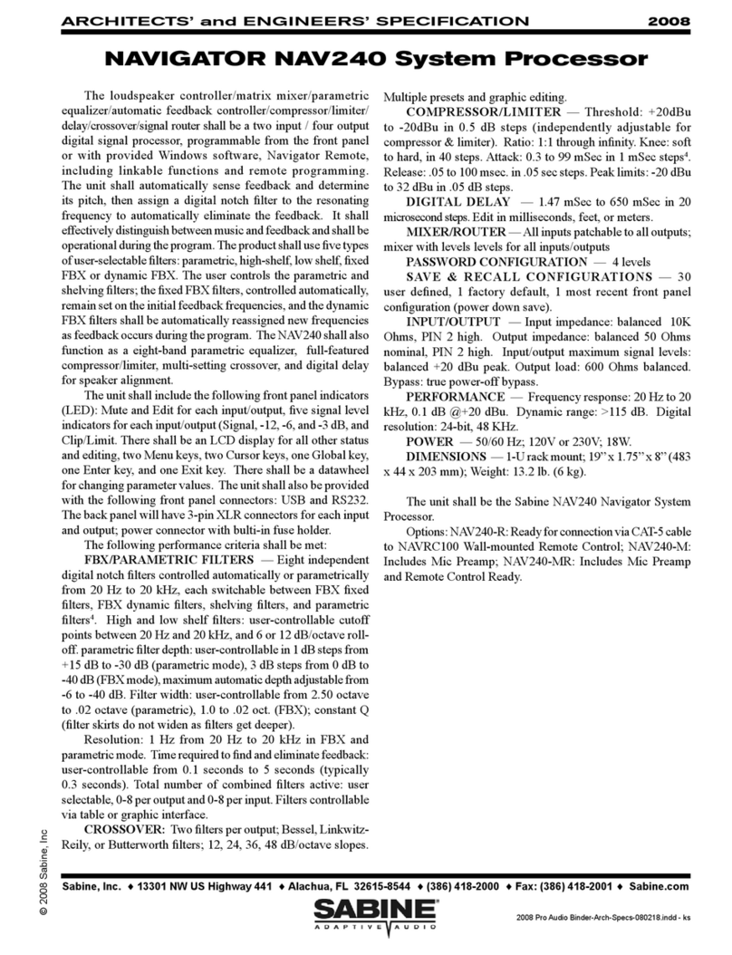
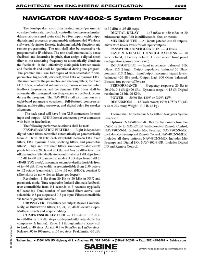
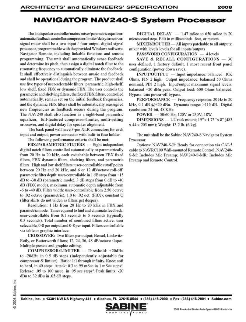
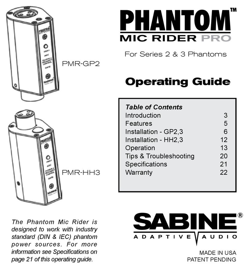
SABINE Navigator User manual

OPERATING
GUIDE
NNAAVVIIGGAATTOORR
SYSTEM PROCESSORS
loudspeaker controller
matrix mixer
signal router
TM
www.Sabine.com

1
Navigator Op Guide 051226.pmd
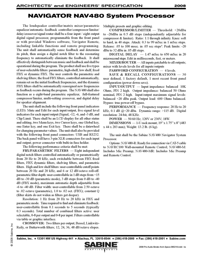
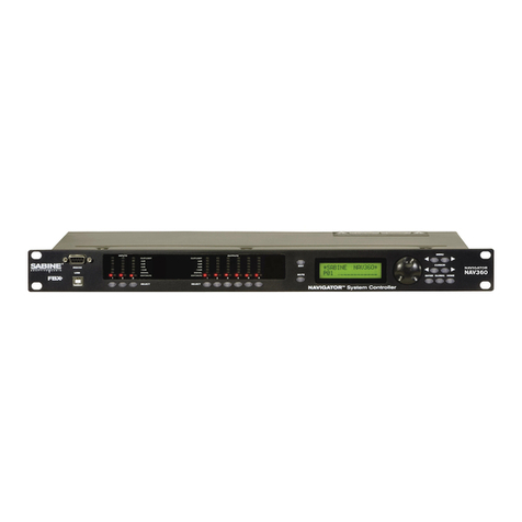
NAV3600 (3 x 6 System Processor)
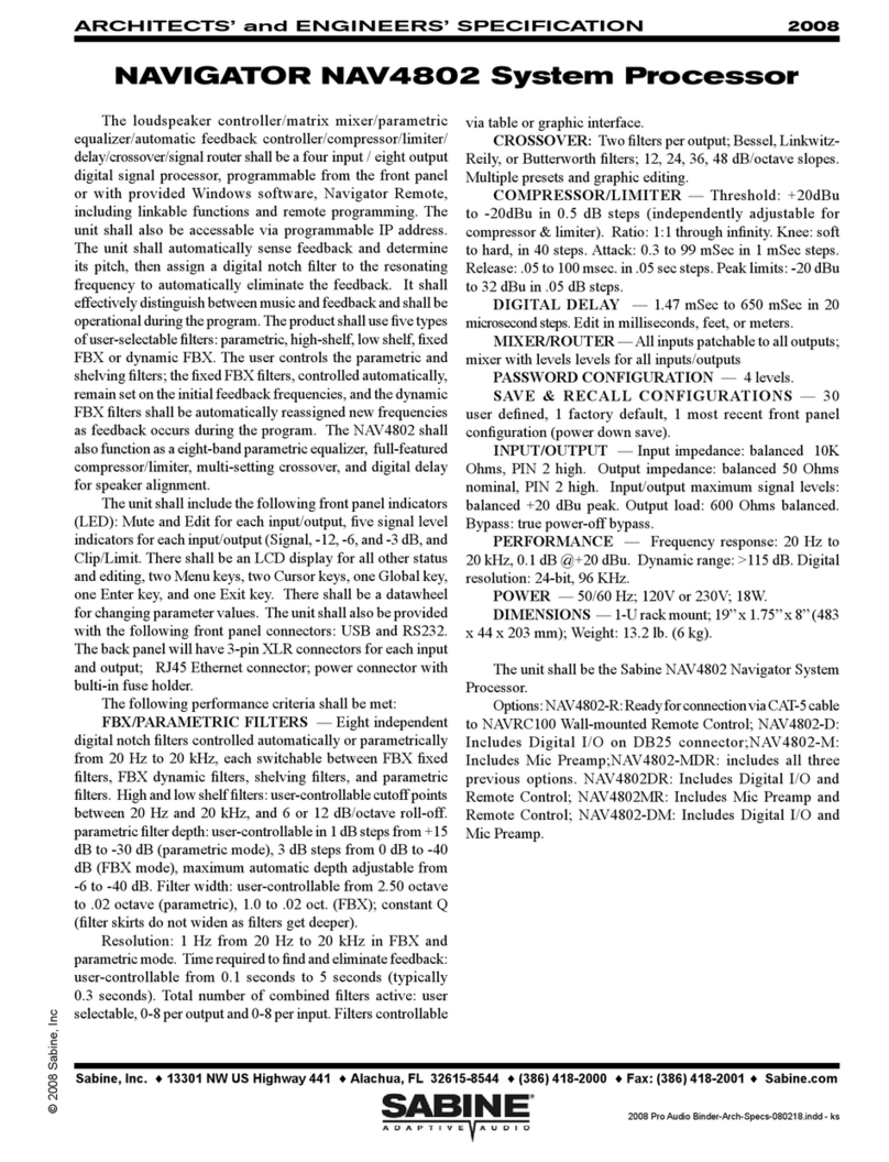
NAV4800 (4 x 8 System Processor)
NAV8800 (8 x 8 System Processor)
NAV3600-EN (3 x 6 System Processor, with Ethernet)
NAV4800-EN (4 x 8 System Processor, with Ethernet)
NAV8800-EN (8 x 8 System Processor, with Ethernet)
Navigator Remote for WindowsTM Software included with every unit; runs up to 16 Navigators
• Full front panel control
• 24-bit A/D and D/A conversion, 40-bit extended processing
• 20 to 20 KHz Frequency Response
• +18 dBu Maximum Signal Input & Output
• Floating Point SHARC Processor
• 115 dB dynamic range
Each Input/Output channel provides
• Precise control of Level and Polarity
• Parametric Filters: up to 6 filters, numeric or graphic control
• Crossover: Bessel, Butterworth, and Linkwitz Reily filters; slopes to 48 dB/octave
• High Shelf Filter (3KHz to 20KHz) and Low Shelf Filter (20 Hz to 1KHz)
• FBX Feedback Exterminator: 8 Filters, with Setup Mode
• Compressor/Limiter, with controls for ratio, threshold, attack. release, and gain
• Digital Delay, with up to 450 msec delay, adjustable in 20 microsecond increments
• Bypass: dedicated switches for all functions
• Mute and Channel buttons, with easy linking
• LED Indicators: Gain/Menu, Mute, Level
• LCD Display: All parameters and status displays
• Store up to 30 programs
• Multiple levels of password security
Back Panel:
• XLR inputs & outputs; Phoenix on 8800 units
• RS-232 Serial input
• Ethernet (-EN units only)
Navigator Remote Software Features:
All front panel controls, plus more, including:
• Graphic filter adjustments
• Passwordprotection
• View & edit frequency response curves
• Store and recall files, setups, programs
• Control and link up to 16 Navigators (-EN units)
• Future-proofFREEFlashRAMupgradecapability: upgradeyourfirmwareandsoftwareusingSabine’s
UpgradeWizard
Summary of Features
SUMMARY OF FEATURES
Operating Guide Version 2: for Sabine Navigators with:
• Navigator Firmware Version 5.04 and up
• Navigator Remote Software Version 5.0 and up

2
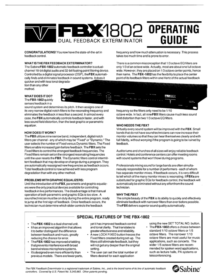
DECLARATION OF CONFORMITY
EN 60065: 1993
EN 60742: 1995
EN 55103-1: 1997
EN 55022: 08:94 + a1:05:05
EN 55103-2: 1997
EC - DECLARATION OF CONFORMITY
CE MARKING
We,theManufacturer
SABINE, INC.
13301 NW US HIGHWAY 441
ALACHUA, FLORIDA USA
declarethatthe product
EQUALIZER
SABINE MODEL NAVIGATOR
Is in conformity with
Council Directive: 73/23/EEC and 89/336/EEC (EMC Directives)
Standardstowhichconformityis declared:
Manufacturer'sSignature:
Date: SEPTEMBER 30, 2005 Name: Doran Oster, Sabine President

3
Navigator Op Guide 051226.pmd
TABLE OF CONTENTS
Table of Contents
Summary of Features.......................................................................................................................................................... 1
Section One: Introduction ................................................................................................................................................. 4
Section Two: Front & Back Panel Views ............................................................................................................................ 5
SectionThree: Navigator Applications .............................................................................................................................. 6
3.1 INSTALLED AUDIO ....................................................................................................................................................................... 6
3.2 PRODUCTION AUDIO .................................................................................................................................................................. 7
Section Four: Using Navigator Front Panel Controls ........................................................................................................ 8
4.1. QUICK START GUIDE TO THE NAVIGATOR FRONT PANEL ..................................................................................................... 9
Section Five: Operating the Navigator ............................................................................................................................ 10
5.1 INPUT MENUS ............................................................................................................................................................................ 10
5.2 OUTPUT MENUS ........................................................................................................................................................................ 12
5.3 SYSTEM MENUS ....................................................................................................................................................................... 14
5.4 INPUT/OUTPUT REFERENCE GUIDE ....................................................................................................................................... 16
5.5. FEEDBACK CONTROL AND PARAMETRIC EQUALIZATION .................................................................................................. 17
5.6. FBX OPERATING INSTRUCTIONS ............................................................................................................................................ 18
Section Six: Using Navigator Remote Software ............................................................................................................. 20
6.1. SYSTEM REQUIREMENTS AND RECOMMENDATIONS ........................................................................................................ 20
6.2. CONNECTIONS ......................................................................................................................................................................... 20
6.3. INSTALLING AND USING THE SOFTWARE ............................................................................................................................. 20
6.4 UPGRADING NAVIGATOR FIRMWARE AND SOFTWARE ....................................................................................................... 21
6.5. NAVIGATOR REMOTE - CONTROL SCREENS ....................................................................................................................... 22
6.6 CREATING A NAVIGATOR NETWORK ...................................................................................................................................... 24
Section Seven: Navigator Engineering Specifications .................................................................................................. 26
Section Eight: Cautions & Warranty ................................................................................................................................. 27

4
Section One: Introduction
Congratulations on your purchase of the Sabine Navigator. This product represents our latest
breakthrough in our never-ending quest to improve the world’s sound.
TheNavigatorscomeinthreebasicinput/outputconfigurations. TheNAV3600isa3 by6,the NAV4800
is a 4 by 8, and the NAV8800 is an 8 by 8. These System Processors are equally at home in both touring
and installation applications, where they provide loudspeaker management, matrix mixing, and signal
routing. State-of-the-art hardware and firmware guarantee superior sound quality and reliability.
All firmware and software can be upgraded using Sabine’s Upgrade Wizard software, included on your
NavigatorCD.
Asidefromthe powerful array offeaturespacked into a single unit (multiplecrossovers, complete signal
routing and mixing, FBX filters, parametric filters, high and low shelf filters, delay, compression, and
limiting), the Navigator also offers a choice of user interfaces.
Computer control: WhenyouinstalltheincludedNavigatorRemoteControlSoftwareyouwill see a very
powerful yet simple user interface. All parameters and system status monitors are available without
buryingyouin cryptic menus. From here you controlall audio, security, linking, and filesavingfunctions,
and you can manage your entire network of Navigators.
Front Panel Control: TheNavigatorcombinesthe best of both worlds. The frontpanelprovidesaccess
to every audio and system function for each device. Gain control for each input and output is one touch
away. LED signal meters for each input and output provide a clear picture of signal status, and editing
isfastwiththedatawheelandcursorkeys. Quickly control multiple channels simultaneously by pressing
several channel buttons at the same time, which is very handy for those global changes.
Serial Remote Control Devices: Navigatorsarecompatiblewith allthemajorserial controllers,including
Crestron, AMX, and Cue.
Attractive wall-mounted switches for controlling presets, gain, muting, and other basic functions will be
available from Sabine soon.
How to Use this Operating Guide
Detailed instructions are provided for all front panel controls, but you will probably be able to get going
after taking a look at the Quick Start page. The instructions apply to all Navigators except where noted.
Laterin this guide is anoverviewofinstallingandusingthe Navigator Remote Control Software. Formore
detailed information please see the Help section of the software.
If you have any questions you may call Sabine’s Customer Service Department at 386-418-2000 from
9:30 am to 6:00 pm EST.
SECTION ONE: INTRODUCTION

5
Navigator Op Guide 051226.pmd
SECTION TWO: FRONT &BACK PANEL VIEWS
NAV8800 Front Panel
NAV8800 Back Panel
Section Two: Front & Back Panel Views
RS-232 Serial In
Connect to serial port
of PC
Options Panel
Connectors for
Ethernet, CobraNet,
or Digital I/O
XLR connectors
Power connector,
fuse, power switch,
and voltage selector
Menu keys
Scroll through
available menus
System Mode / Coarse Edit Mode
Enter system menus
Hold while turning datawheel for
coarse adjustments
Data wheel
Edits parameter
values
Cursor keys
Moves cursor through
available parameters
INPUT Selector
Selects channel for
editing in current Menu
LCD Display
Input & Output
signal indicators
NAV3600 Back Panel
NAV4800 Front Panel
NAV4800 Back Panel
NAV3600 Front Panel
INPUT Mute
Mutes audio for
this input Exit
Return to main
screen
OUTPUT Selector
Selects channel for
editing in current Menu
INPUTSOUTPUTS
Phoenix 3-pin Connectors

6
SECTION T HREE: NAVIGATOR APPLICATIONS
Section Three: Navigator Applications
3.1 INSTALLED AUDIO
House of Worship
Conference Room - Distributed Audio
NAV4800
Laptop Control
NAV8800

7
Navigator Op Guide 051226.pmd
SECTION T HREE: NAVIGATOR APPLICATIONS
3.2 PRODUCTION AUDIO
Stereo 3-way, with Subs
Laptop Control
Left, Center,Right
NAV4800
NAV3600

8
SECTION FOUR: USING NAVIGATOR CONTROLS
Section Four: Using Navigator Front Panel Controls
1. Mute keys - Mute/Unmute input and output channels. When an input channel is muted, the
corresponding red LED will be lit.
2. Gain/Menu keys - Selectsthe corresponding channel for the LCD menu display indicated by a green
LED. The last modified menu will be displayed on the LCD.
CHANNEL LINKING: Linking multiple channels is accomplished by pressing and holding one channel’s
menukey, then pushing the other desired channels.Oryoucanpressanddrag your finger across several
channels. Linking is very powerful - it simplifies programming for common parameter values across
multiple channels. Multiple inputs can be linked together and multiple outputs can be linked together.
Inputs and Outputs are linked separately.
3. Peak Level LEDs - Indicates the current peak level of the Signal:
Signal,-12dB, -6dB, -3dB, Clip/Limit.TheInputClip LEDreferencestothe device’s maximum headroom.
The Output Limit LED references to the threshold of the limiter.
4. LCD -Shows all the necessary information to control the unit.
5. Rotary Data Wheel - Changes parameter data values. The wheel has travel velocity sensing which
allow for large incremental data modifications. For coarse modification of delay and frequency (1 Hz
resolution)values,pressing theEnter/Sys keysimultaneously will increment/decrement the data value
by 100X.
6. Menu Control keys - The two Menu control keys move through the menus in a linear format.
<<Menu: Previous menu screen
Menu>>: Next menu screen
7. Cursor Control Keys - After choosing a menu to work with, use these keys to move around within
each screen.
<<Cursor: Previous cursor position in the menu screen
Cursor>>: Next cursor position in the menu screen
8. Enter/Sys: Press this key to access the System Menu. These are the global parameters of the
device. Enter is used only in the System Menu to proceed with selected actions, and in the FBX screen
to initiate Setup mode.
Fast scrolling with the Enter/Sys key: Press this key while turning the data wheel to modify delay
and frequency (1 Hz resolution mode) data values by 100X.
Exit: Exit to the Main Menu
2.
1.
3. 4. 5.
7.
6.
8.
SLKHBXOABCOADSXC
TECHTIP
For fast scrolling
of frequency or
delay values,
hold the Enter Key
while turning the
datawheel

9
Navigator Op Guide 051226.pmd
SECTION FOUR: USING NAVIGATOR CONTROLS
4.1. QUICK START GUIDE TO THE NAVIGATOR FRONT PANEL
· After powering up the unit, the following initialization screen is displayed on the LCD:
· The initialization process takes about 8 seconds and during that period the unit boots and displays the
Navigatorfirmwareversion.
· After the initialization process is finished the Navigator displays its main screen:
· The screen shows the current program number and program name assigned to the unit. The program
assigned is always the last program the user recalled or stored before powering down the unit.
The Navigator is now ready to go.
4.1.1 Configuring The Navigator
Workingwith your Navigator is easy. Followthesebasicstepstoget started. For details on working within
each menu, please read Section Five on operating the Navigator.
1. Signal Routing: You first need to get your inputs routed to the appropriate outputs. You can do this
in two ways.
A. Press Enter to enter the System Menu, press the >>Menu key until you get to the
Configuration Menu, and choose one of the preset configurations. This is the fast way to get
all your routing done.
B. Or you can press the green Menu key on one of the outputs, press the >>Menu until you get
to the Source Menu, and choose which of the inputs you want to patch to this particular output.
2. Set Input/Output Gain: The first menu you see when pressing the green Menu/Gain key on each
input or output is the Signal Menu. The cursor is already in the Level field, and you can immediately
turn the datawheel to adjust the input and output gain of each channel. This fast access to gain is very
handy for quick adjustments during your program.
3. Mixing: Mixing for each output is done in the Source Menu of each output (see 1.B. above). In this
menu each input has a gain control so you can set the levels to create just the right mix in this particular
output.
4. Crossover Filters: At this point you may want to set the crossover filters for each of the outputs.
You are essentially controlling which band of frequencies you will send to each of your speakers or
speaker systems. Press the green menu key for the output you want to set, and press the Menu key
until you get to the XOVER Menu. You will set filters for the lower and upper rolloff points, the slopes
of the filters, and type of each filter.
5. Equalization: You may want to adjust the frequency response of your system. The Navigator gives
you a powerful set of EQ tools. For each input and output you can use up to six filters, and these can
be either Parametric, HIgh Shelving, or Low Shelving filters. Press the green Menu button on any input
or output channel to access the EQ Menu.
6. FBX Feedback Exterminator: Each input channel includes 8 patented FBX feedback control filters.
Use the FBX Mode menu to begin Setup Mode for maximum gain before feedback. See the results of
the process in the FBX Menu, and change the default FBX parameters on the FBX Global Menu.
7. Save your work: You know how important this one is. If you are editing in the input/output menus,
press Exit to get to the Main Menu. Then press Enter to get to the System Menus, and scroll to the Store
Menu. Save and name your program here. Do it early and often!
10
Section Five: Operating the Navigator
5.1 INPUT MENUS
Each of the Navigator input channels has a separate Menu key. There are 7 function menus for each
inputchannel,andyoucyclethrough these by pressing the Menu keys. The first line intheLCDindicates
which input channel you are editing, and shows the name of that channel if you have added one (for
example, IN_1: ____), The menus are arranged in a linear fashion. Scroll to the right to reach the end,
then scroll back to the left until you reach the beginning. Use the Cursor keys to select a parameter to
edit, and use the Data Wheel to make your edits.
Signal
· LEVEL: Gain, -40.00 dB to +15.00 dB in 0.25 dB steps.
· POL: Polarity, can be normal (+) or inverted (-).
· DELAY: Delay in 21 microsecond steps. Can be displayed in ms, ft or m. The time unit of the delay can
be changed in the System menu. The maximum delay permitted is 21,600 steps (450ms).
EQ
· EQ#: Selects one of the 6 available equalizer filters.
· LEVEL: Adjusts EQ level. Ranges from -30.00dB to +15.00dB in 0.25dB steps.
· FREQ: EQ center frequency. Ranges from 20 to 20,000 Hz in either 1 Hz steps or 1/36 octave steps.
The frequency steps can be selected in the System Menu.
· BW: EQ Bandwidth. Ranges from 0.02 to 2.50 octaves in steps of 0.01 octave steps for PEQ. The Q
value is automatically shown beneath the octave value. For Lo-Shf or Hi-Shf, it is either 6 or 12dB/Oct.
· Type: Type of EQ. The types can be PEQ (parametric), Lo-Shf (Low shelving), and Hi-Shf (High
shelving).
FBX Feedback Exterminator
· EQ#: Selects one of the 8 available FBX filters.
· TYPE: Choose Fixed for gain before feedback, Dynamic for feedback control during the show. See
section 5.5 for a complete guide to using the FBX function.
· LVL: Shows level in dB of the FBX filter (not editable).
· FREQ: Shows center frequency of the FBX filter (not editable).
· BW: Shows the width of the FBX filter (not editable).
SECTION FIVE: OPERATING THE NAVIGATOR
NAV3600
LCD Display has
only 2 lines. Use
Cursor key to
access all
parameters in
each window
NAV4800 & NAV8800
NAV3600
NAV4800 & NAV8800
NAV3600
NAV4800 & NAV8800
NAV3600

11
Navigator Op Guide 051226.pmd
FBX-Global Parameters
· LOCK: ThisreferstoFixedfiltersonly,whichbydefinitionalreadyare fixedin their centerpoint position.
Locking prevents the filter from getting deeper. Locked is the recommended setting. Ready Mode
automatically locks fixed filters.
· BYPASS: Bypasses all FBX filters on this Input channel. On indicates bypass; Off indicates FBX is
active.
· RSTDYN: Reset Dynamic FBX filters. Turning to on toggles the reset function.
· DEPTH: Sets maximum depth of all FBX filters on this input channel. Range is 0 to -84dB.
· WIDTH: Sets default width of all FBX filters on this input channel. Range is 0.01 to 1.00 octave.
· SENS:Setsthe Sensitivity of the FBXalgorithmto the difference between musicandfeedback. Range
is 1-5.
· PERS: Sets persistence - how long feedback can persist before a filter is set. Range is 1-5.
· Factory Defaults are recommended for Sensitivity, and Persistence settings.
FBX-Mode
· SETUP MODE: On engages FBX Setup mode. Use this for setup only - not for use during the show.
Thisstepprovidesmaximumgainbefore feedback. Follow on-screen instructions and raise gain slowly.
For a step-by-step guide to using the FBX see section 5.5.
Compressor
· THRESH: Compressor Threshold. Ranges from -20 to +20dBu in 0.5dB steps.
· ATTACK: Attack time. Ranges from 0.3 to 1ms in 0.1ms steps; from 1 to 100ms in 1ms steps.
· RELEASE: Release time. Can be set at 2X, 4X, 8X, 16X or 32X the attack time.
· RATIO: Set compression ratio, 1:1 to 40:1 (Limit).
SECTION FIVE: OPERATING THE NAVIGATOR
NAV4800 & NAV8800
NAV3600
NAV4800 & NAV8800 NAV3600
NAV4800 & NAV8800
NAV3600

12
Channel Name
· Name: Channel name. The maximum is 6 characters in length. Use the datawheel to scroll through all
the possible characters, and use the cursor keys to move to the next space. Once the name is created
it will appear in the upper field of this window.
5.2 OUTPUT MENUS
Each output channel of the Navigator has a separate menu key. There are 6 menus for each output
channel. The menus cycle in a linear fashion, just like the input menus. Use the Cursor keys to select
a parameter to edit, and use the Data Wheel to make your edits.
Signal
· LEVEL: Gain, -40.00dB to +15.00dB in 0.25dB steps.
· POL: Polarity, can be normal (+) or inverted (-).
· DELAY: Delay is adjustable in 21 microsecond steps and displayed in ms, ft or m. The time unit of the
delay can be changed in the System menu. The maximum available delay is 450ms.
EQ
· EQ#: Selects one of the 6 available Equalizer filters.
· LEVEL: EQ level. Ranges from -30.00dB to +15.00dB in 0.25dB steps.
· FREQ: EQ center frequency. Ranges from 20 to 20,000Hz in either 1Hz steps or 1/36 octave steps.
The frequency steps can be selected in the System Menu.
· BW: EQ Bandwidth. Ranges from 0.02 to 2.50 octaves in steps of 0.01 octave steps for PEQ. The Q
value is automatically shown beneath the octave value. For Lo-Slf or Hi-Shf, it is either 6 or 12dB/Oct.
· Type: Type of EQ. The types can be parametric (PEQ), Lo-Shf (Low shelving), and Hi-Shf (High
shelving).
SECTION FIVE: OPERATING THE NAVIGATOR
NAV3600
LCD Display has
only 2 lines. Use
Cursor key to
access all
parameters in
each window
NAV4800 & NAV8800
NAV3600
NAV4800 & NAV8800
NAV3600
NAV4800 & NAV8800
NAV3600

13
Navigator Op Guide 051226.pmd
Crossover
· FTRL: Choose the type of low frequency filter (high pass). Types can be Buttwrth (Butterworth), Link-
Ri (Linkwitz-Riley) or Bessel.
· FRQL: Filter cut-off frequency of low frequency crossover point (high pass). Ranges from 20 to
20,000Hz in either 1Hz steps or 1/36 octave steps. Select frequency resolution in the System Menu.
· SLPL: Filter Slopeoflow frequency crossover point (high pass). Rangesfrom6 to 48dB/octave in 6dB/
octave steps. If the selected Filter Type is Linkwitz Riley, the available slopes are 12 / 24 / 36 / 48 dB/
octave.
· FTRH: Choose the type of high frequency filter (low pass). Types can be Buttwrth (Butterworth), Link-
Ri (Linkwitz-Riley) or Bessel..
· FRQH: Filter cut-off frequency of high frequency crossover point (low pass). Ranges from 20 to
20,000Hz in either 1Hz steps or 1/36 octave steps. Select frequency resolution in the System Menu.
· SLPH: Filter Slopeofhighfrequencycrossoverpoint (low pass). Ranges from 6 to 48dB/octave in6dB/
octave steps. If the selected Filter Type is Linkwitz Riley, the available slopes are 12 / 24 / 36 / 48 dB/
octave.
Compressor
· THRESH: Compressor Threshold. Ranges from -20 to +20dBu in 0.5dB steps.
· ATTACK: Attack time. Ranges from 0.3 to 1ms in 0.1ms steps; from 1 to 100ms in 1ms steps.
· RELEASE: Release time. Can be set at 2X, 4X, 8X, 16X or 32X the attack time.
· RATIO: Set compression ratio, 1:1 to 40:1 (Limit).
SECTION FIVE: OPERATING THE NAVIGATOR
Filter
Configuration
Low crossover
point (FTRL)
High crossover
point (FTRH)
None Off Off
FTRL
FTRH
FTRL FTRH
Band
p
ass NOT Off NOT Off
Hi
g
h
p
ass NOT Off Off
Low
p
ass Off NOT Off
NAV4800 & NAV8800
NAV3600
NAV4800 & NAV8800
NAV3600

14
Input Source
· 1, 2, 3, 4 – Input channel source for the current output channel. This is your sub-mixer for each output
of the Navigator. Values range from 0.00 (Maximim level) to -40, then OFF, which mutes that input for
the output you are editing.
Channel Name
· Refer to the Input Menus for details.
5.3 SYSTEM MENUS
The System Menus allow you to control and change global parameters that are related to the general
operation of the Navigator. Access these menus by pressing the System key in the main menu (when
no Input/Output or System Menu is activated). Press EXIT to access the Main Menu, then SYSTEM to
enter the System Menus. All System Menus require the Enter key to be pressed to confirm the selected
action.
Program Recall
The Navigator has a built in non-volatile memory that can store up to 30 different program setups. A
program can be recalled using this menu.
· PROG: Program Number to be recalled..
· NAME: Program Name of the program. This is read only; names can be changed in the Store menu.
Program Store
The Navigator has a built in non-volatile memory that can store up to 30 different program setups. A
programcan be stored using this menu. Theoldprogramwiththesameprogram number will be replaced.
Oncethe program is storedin the flash memory,it can be recalled at a latertime, even after powerdown.
SECTION FIVE: OPERATING THE NAVIGATOR
NAV3600
LCD Display has
only 2 lines. Use
Cursor key to
access all
parameters in
each window
NAV4800 & NAV8800
NAV3600
NAV4800 & NAV8800
NAV3600
NAV4800 & NAV8800
NAV3600
NAV4800 & NAV8800
NAV3600

15
Navigator Op Guide 051226.pmd
· PROG: Program Number for the current data to be stored.
· NAME: Program Name, allows a maximum length of 12 characters.
Configuration
· MODE - configures the mode of operation.
Mode: Out 1 Out 2 Out 3 Out 4 Out 5 Out 6 Out 7 Out 8
None Any Any Any Any Any Any Any Any
Stereo 2-Way In1 In1 In2 In2 Any Any Any Any
Stereo 3-Way In1 In1 In1 In2 In2 In2 Any Any
Stereo 4-Way In1 In1 In1 In1 In2 In2 In2 In2
The unit assigns the Input source for the corresponding outputs when the Mode of
Configurationis selected. The crossover point parameters like the filter type, cut-off frequency
and slope have to be configured manually in the Xover Menu in each Output menu.
*Note: The configuration mode configures the input sources when selected. The user can
change the source afterwards if desired. It does not keep the configuration in memory.
Copy Parameters
Copychannel parameters fromthesourceto the target. WhentheSourceand Targets areboth
Inputs or Outputs, all audio parameters will be copied. When one of the Source or the Target
is an input while the other is an output, only the Level, Polarity, Delay and EQ are copied.
· SOURCE: Channel to be copied from.
· TARGET: Channel to be copied to.
General System Parameters
· FREQ MODE: Selects the frequency control mode for EQ and crossover filters. Can be 36
steps/octave or All Frequencies (1 Hz resolution).
· DELAY UNIT: ms, ft or m.
· DEVICE#: Assigns the device ID from 1 to 16. This ID is useful when a network of more than
SECTION FIVE: OPERATING THE NAVIGATOR
NAV4800 & NAV8800
NAV3600
NAV4800 & NAV8800
NAV3600
NAV4800 & NAV8800
NAV3600

16
1 unit is present.
· PORT: Choose control port. RS232 for direct connection to a computer, or CAT-5 for Ethernet.
Security
The Navigator enables the user to secure the unit and prevent undesired changes in the setup. In order
to make changes to the security levels the user must enter the correct password.
· MENU - Selects the menu to be locked/unlocked. The options are:
•In-Signal: Input Signal Menu (Level, Polarity, Delay).
•In-EQ: Input EQ Menu.
•In-Name: Input Channel Name Menu
•Out-Signal: Output Signal Menu (Level, Polarity, Delay).
•Out-EQ: Output EQ Menu.
•Out-Xover: Output Crossover Menu.
•Out-Limit: Output Limit Menu.
•Out-Source: Output Source Menu.
•Out-Name: Output Channel Name Menu.
•System: System Menu
· LOCK: Engages lock (Yes) or unlock (No) for the corresponding menu.
· PASSWORD: Enter your 4-character password here. Initial password creation must be done within
NavigatorRemote Software. Entering the samepasswordhereinitiatesthe lockout function. Press Enter
and your Navigator front panel controls will be locked according to the menu selections you made. You
can alter those selections via the front panel or through the software.
5.4 INPUT/OUTPUT REFERENCE GUIDE
This chart shows all the parameters and edit values for each control on each menu. Use this as your
reference for ranges of all parameters in each menu.
SECTION FIVE: OPERATING THE NAVIGATOR
NAV3600
LCD Display has
only 2 lines. Use
Cursor key to
access all
parameters in
each window
<<Menu>> <<Cursor>>
Level Signal LEVEL -40 15 0.25 dB
Polarity Signal POL
Delay Signal DELAY 0 21,600 1 21us steps
EQ Number EQ EQ# 1 6 1
EQ Level EQ LEVEL -30 15 0.25 dB
EQ Frequency EQ FREQ 20 20,000 1 Hz
EQ Bandwidth EQ BW 0.02 2.5 0.01 Octave
Crossover Low XOver FTRL
Crossover Low XOver FRQL 20 20,000 1 Hz
Crossover Low XOver SLPL 6 48 6 dB/octave
Crossover High XOver FTRH
Crossover High XOver FRQH 20 20,000 1 Hz
Crossover High XOver SLPH 6 48 6 dB/octave
Limiter Threshold Limit THRESH -20 20 0.5 dBu
Limiter Attack Limit ATTACK 0.3 100 0.1/1 ms
Limiter Release Limit RELEASE
Source Select Source 1, 2, 3, 4
Channel Name Ch-Name NAME
Parameters Min Max Ste
p
s
2 / 4 / 8 / 16 / 32X Attack time
Off / On
6 characters
Units
+ / -
Off / Butterworth / Linkwitz-Riley / Bessel
NAV4800 & NAV8800
NAV3600

17
Navigator Op Guide 051226.pmd
5.5. FEEDBACK CONTROL AND PARAMETRIC EQUALIZATION
Operation of the FBX Feedback Exterminator section of the front panel of your Navigator is simple, but
mayrequireabriefexplanationfor those of you unfamiliar with Sabine FBX products and/orterminology.
Let’s begin by defining a few key terms.
5.4.1. Glossary of Terms
•FEEDBACK describes what happens when a loudspeaker disperses sound back into an amplified
microphone, at a level sufficient to allow one or more frequencies to ring out of control. Feedback can
occur at any frequency, but is especially painful at mid to high frequencies. The specific frequencies
thatfeedbackinaparticularsituationdependon the acoustics of the environment, the placement of the
microphone(s)andspeaker(s),theresponsecharacteristicsofthesoundsystem components,andthe
volume of amplification. Anyone who has operated a sound system or attended a conference or a
concert is familiar with feedback and its unpleasant consequences!
•APARAMETRIC EQUALIZER allows the user to precisely specify three critical values that
determine an equalizer’s characteristics: the center frequency of the EQ band that is boosted or cut
(measured in Hertz), the amount of boost or cut imposed at the center point (measured in dB), and
the width of the bell-curve shaped frequency band that is affected (typically measured in octaves).
• An FBX FILTER is essentially an automatically placed, narrowly attenuated parametric filter, with
the center point of its narrow cut tuned to a precise frequency that feeds back when a sound system
amplifies one or more microphones to a sufficient volume. The Navigator will automatically place
up to 8 FBX filters in the signal path, corresponding to 8 distinct frequencies of feedback.
•AFIXED FBX FILTER will not move from the original set frequency of the filter. Once it sets itself,
it remains at the same frequency. The system’s gain before feedback is limited primarily by the
number of fixed filters; i.e., increasing the number of fixed filters increases the system’s gain before
feedback. However, unless it is LOCKED, a FIXED FILTER may move its notch deeper without
changing frequency. Fixed filters are typically set by turning up system gain to the point of feedback
prior to sound check or performance, and they represent the “first layer” of feedback protection.
•ADYNAMIC FBX FILTER acts like a Fixed filter, until all available FBX filters (Fixed or Dynamic)
are in use and a new frequency begins to feedback. When this happens, whichever Dynamic filter
wasset earliest in the performance will dropitsoriginalfrequencyandmovetothe new one. Dynamic
filters are especially useful with mobile or wireless microphones (where feedback frequencies may
change due to microphone repositioning) and represent the “second layer” of feedback protection.
Note that both Fixed and Dynamic filters can be set while music is playing (except when in Setup
Mode). One of the distinguishing properties of the Sabine FBX algorithm is its ability to distinguish
music (or speech, or other sounds) from feedback.
•ALOCKED FBX FILTER is a Fixed filter locked in place; i.e., it cannot get any deeper or change
its frequency. Locked fixed filters are no longer adaptive. Locking Fixed filters ensures your first
layer of feedback protection is always in place -- highly recommended.
•FILTER WIDTH generally refers to the width (measured in octaves, or fractions thereof)
of a filter, including graphic EQ filters, parametric filters, and FBX filters. More specifically, width
is defined by determining the outer frequencies (surrounding the filter center point) that are altered
± 3 dB when the filter is imposed.
•CONSTANT Q filters are filters whose widths remain constant regardless of the amount of boost or
attenuation imposed by the filters. Some EQ units on the market are Constant Q; others are
Proportional Q, meaning the filter gets wider as it gets deeper. All Sabine products use Constant
Q filters, to prevent affecting any more sound than necessary.
•FBX Setup Mode refers to Sabine’s exceptionally fast method of placing FBX filters during sound
system setup. Think of Setup mode as your key to achieving one of the main benefits of the FBX:
getting more gain before feedback. In Setup the FBX is very sensitive so do not talk into the mics
during setup,and try to keep roomnoisetoaminimum.Setupisdesignedto allow feedback to occur
at lower input levels, and it imposes a strong limiter on the feedback output as it occurs. The net
result is that you are able to ring out feedback more quickly, and at a much quieter level!
NOTE: MAKE SURE Setup Mode IS OFF and Ready Mode IS ENGAGED WHEN YOU USE THE
NAVIGATOR OR YOUR AUDIO SIGNAL QUALITY MAY SUFFER!
SECTION FIVE: OPERATING THE NAVIGATOR

18
SECTION FIVE: OPERATING THE NAVIGATOR
5.6. FBX OPERATING INSTRUCTIONS
Follow these steps to obtain the maximum gain before feedback, with minimal or no loss in the tonal
quality of your program. You should always setup one channel at a time by turning down the other
channels of the mixer or power amplifiers.
STEP ONE: EQUIPMENT SETUP
Set up your sound system and position all the speakers and microphones you anticipate using. When
possible, avoid placing microphones directly in front of speakers. Patch the Navigator into the system
(refertosectionThreeforinstallationconfigurations). Setyourlevelsfornominalperformancebutavoid
raising the gain enough to induce feedback. If you are using a graphic EQ, adjust only for the desired
tonal qualities, but DO NOT NOTCH FOR FEEDBACK. If there is any equipment in the signal path that
incorporates a noise gate function, you MUST DISENGAGE these noise gates prior to the setup
procedure. You may reengage them upon setup conclusion. For best results setup your FBX on one
input channel at a time. You can mute the audio in the other input channels.
STEP TWO: CHOOSE YOUR FILTER TYPES and REMOVE BYPASS
The default filter setting for your Navigator are 6 FBX Fixed Filters and 2 FBX Dynamic Filters per input
channel. Youmay change that mix offilters, and this shouldbe done before you enterSetup Mode. You
can always alter the mix of FBX filters and repeat the Setup procedure. To change filter types, choose
the FBX Menu in the Input Channel you are working on.
The factory default for the FBX is BYPASS: On, which means the FBX section is Bypassed. Before
you start FBX Setup, select the input channel you are working on, then go to the FBX Global Menu. Set
the BYPASS to Off, meaning the FBX section is now active.
STEP THREE: ENGAGE SETUP MODE - RESET FILTERS
Choose an input channel and select the FBX-Mode Menu. Using the datawheel select “Setup” in the
SETUP MODE field, then press ENTER. Press ENTER again to confirm Setup Mode.
Setup mode
clears all Fixed & Dynamic filters. Do not use Setup mode during your performance.
STEP FOUR: RAISE MASTER GAIN
Makesure yourpoweramplifieris turned upandyourmicrophones areturnedon. Slowlyraise the master
gain of your mixer (or the submix for this input channel of the Navigator) until the first feedback begins.
The FBX will quickly remove the feedback by setting the first filter. Continue to raise the gain slowly.
Try to avoid making two or more frequencies feed back at the same time, which sometimes happens
if the gain is raised too quickly. As new frequencies feed back, new filters will be placed. (Note:
sometimesthesamefrequencywillfeedbackasecondtime,andanearlierfilterwillnotchmoredeeply.)
Continue raising the gain. Setup mode will end and Ready mode will be engaged in one of two ways:
1. All of the Fixed filters and at least the first Dynamic filter are set. This will automatically turn Setup
Mode off and the FBX Menu window will be displayed. At this point STOP RAISING THE GAIN!
Press enter to begin Setup -
NAV4800 (above), NAV3600 (below)
Raise gain slowly; Setup automatically ends
or got to Ready mode any time by pressing
Exit - NAV4800 (above), NAV3600 (below)
NAV3600
LCD Display has
only 2 lines. Use
Cursor key to
access all
parameters in
each window
FBXBypass
Be sure and take
the FBX section
out of Bypass
before setup! Do
this in the FBX
Global Menu.

19
Navigator Op Guide 051226.pmd
2. You’ve set as many filters as you need or want, even though you haven’t used them all. Press EXIT
to prevent any more Fixed filters from setting, or any of the set Fixed filters from notching more
deeply. Pressing EXIT exits Setup Mode and the FBX Menu window will be displayed.
You are now ready to begin your program!
See the results: In the FBX Menu you can view the parameters of all your FBX Filters. Scroll through
all the filters in the FBX# field. You may edit the type of filter, but not the level (LVL), width (BW), or
frequency (FREQ). You may want to create parametric filters based on the results of your FBX Setup,
en repeat the Setup procedure to maximize system gain.
5.6.1. FBX Setup Mode Cautions & Alternate Setup Procedure
SetupModeisdesignedtoallowfastandquietfeedbackeliminationduringsetup.SetupMode shouldONLY
be used for pre-performance setup. DO NOT USE Setup Mode DURING A PERFORMANCE! This will
producedistortedaudioandsetfiltersonmusicoraudioprogram.SetupModealsomaynotworkwell during
setup in a very noisy environment. To speed up feedback elimination, Setup relaxes the FBX criteria for
distinguishing“good”audiofromfeedbackandplacesfiltersmorereadily. Iftheenvironmentisnoisy,there
is a greater likelihood of placing a filter on audio that is not feedback.
If you are working in a noisly environment you can still get the benefit of the Setup procedure, which is
more gain before feedback. Instead of Starting in the FBX Mode Menu, begin in the FBX Global Menu.
This procedure willstill eliminate feedback very quickly, though not as quickly as Setup Mode, and without
reducing the volume of the feedback before it is filtered out.
1. Change the LOCK setting to Off. Now the Fixed filters are available to react to feedback.
2. Follow Step Four of the Setup procedure oulined above -- raise the gain for this input channel.
3. Continueraisingthegainuntilyouachievethegainbeforefeedbackyourequire,oryousetallthefixed
filters. You cna see the results of this procedure in the FBX Menu (shown above).
4. VERY IMPORTANT: Go back to the FBC Global Menu and set LOCK to On. This will lock the fixed
filters and prevent them from going any deeper. If you use the factopry default settings you will still have
two dynamic fitlers available for autoimatic feedback control during the program.
Whetheror not SetupMode is used,theendresultof setting up FBXfiltersshouldbeidentical. Your sound
system will have clearer, louder, feedback-free sound.
5.6.2. FBX Feedback Exterminator - Global Parameters
A unique feature of the FBX Feedback Exterminator is the ability to adjust the way the algorithm reacts
to feedback. Unlike other feedback controllers, you can create and save your own customized versions
of the FBX.
See section 5.1 Input Menus for instructions on using the Global parameters of the FBX.
Sensitivity andPersistence arecontrolsthat allow thespeedandanalysisof the FBX algorithmtomatch
the type of audio program. Some audio programs, notably certain types of classical music, produce
occasional waveforms that are difficult to distinguish from acoustic feedback. The factory default
SensitivityandPersistence values should work in almostallconditions; however, you may change them
if necessary to prevent the possibility of triggering a false filter, or to more quickly set the FBX filters.
There is a trade-off between speed of filter placement and how carefully the filter is placed. More
demanding audio sources (that is, program material with musical content that is similar to feedback, like
flutes and organs) may require higher Sensitivity & Persistence settings, which will slightly slow down
the speed of filter placement, but decrease any possibility of mistaking program audio for feedback.
Lower settings are recommended when you need faster reaction during speech-only programs.
SECTION FIVE: OPERATING THE NAVIGATOR
This manual suits for next models
6
Table of contents
Other SABINE Computer Hardware manuals

SABINE
SABINE NAVIGATOR NAV360-S User guide

SABINE
SABINE Phantom Mic Rider Pro PMR-GP2 User manual

SABINE
SABINE FBX-1802 User manual

SABINE
SABINE NAVIGATOR NAV240-S User guide

SABINE
SABINE NAVIGATOR NAV480-S User guide

SABINE
SABINE NAVIGATOR NAV4802 User guide

SABINE
SABINE FBX MODEL R V1.0 User manual

SABINE
SABINE NAVIGATOR NAV360 User guide

SABINE
SABINE NAVIGATOR NAV240 User guide

SABINE
SABINE NAVIGATOR NAV8802-S User guide