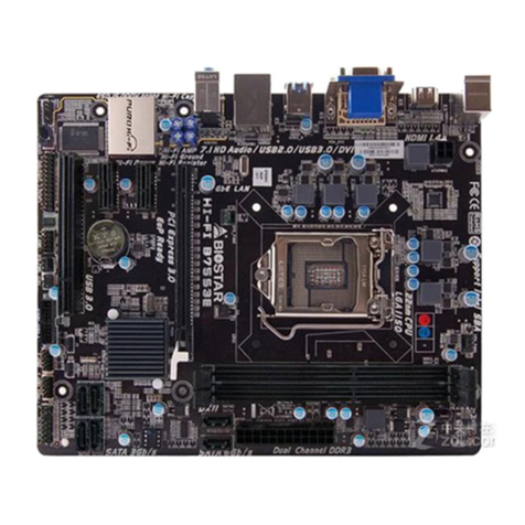
Biostar BIH61-IHP User manual

FCC Warning
This equipment has been tested and found to comply with the limits for a Class A digital device, pursuant
to part 15 of the FCC Rules. These limits are designed to provide reasonable protecon against harmful
interference when the equipment is operated in a commercial environment. This equipment generates, uses,
and can radiate radio frequency energy and, if not installed and used in accordance with the instrucon
manual, may cause harmful interference to radio communicaons. Operaon of this equipment in a
residenal area is likely to cause harmful interference in which case the user will be required to correct the
interference at his own expense.

2 | Table Of Contents
BIH61-IHP User’s Manual
Table Of Contents
FCC Warning ����������������������������������������������������������������������������������������������������������� 1
Chapter 1: Introducon������������������������������������������������������������������������������������������� 3
1.1 Before You Start .....................................................................................................................................3
1.2 Specicaons .........................................................................................................................................4
1.3 Rear Panel Connectors...........................................................................................................................6
1.4 Motherboard Layout..............................................................................................................................7
Chapter 2: Hardware installaon����������������������������������������������������������������������������� 9
2.1 Install Central Processing Unit (CPU) .....................................................................................................9
2.2 Install a Heatsink ..................................................................................................................................11
2.3 Fan Headers .........................................................................................................................................12
2.4 Installing Memory Module...................................................................................................................13
2.5 Expansion Slots ....................................................................................................................................14
2.6 Jumper & Switch Seng ......................................................................................................................16
2.7 Headers & Connectors .........................................................................................................................18

Chapter 1: Introducon | 3
BIH61-IHP User’s Manual
Chapter 1: Introducon
1�1 Before You Start
Thank you for choosing our product. Before you start installing the motherboard, please make sure you
follow the instrucons below:
• Prepare a dry and stable working environment with sucient lighng.
• Always disconnect the computer from power outlet before operaon.
• Before you take the motherboard out from an-stac bag, ground yourself properly by touching
any safely grounded appliance, or use grounded wrist strap to remove the stac charge.
• Avoid touching the components on motherboard or the rear side of the board unless necessary.
Hold the board on the edge, do not try to bend or ex the board.
• Do not leave any unfastened small parts inside the case aer installaon. Loose parts will cause
short circuits which may damage the equipment.
• Keep the computer from dangerous area, such as heat source, humid air and water.
• The operang temperatures of the computer should be 0 to 45 degrees Celsius.
• To avoid injury, be careful of:
Sharp pins on headers and connectors
Rough edges and sharp corners on the chassis
Damage to wires that could cause a short circuit
Note
»
»The package contents may be dierent due to the sales region or models in which it was sold. For more
informaon about the standard package in your region, please contact your dealer or sales representave.

4 | Chapter 1: Introducon
BIH61-IHP User’s Manual
1�2 Specifications
Dimensions 170 x 170 x 1.6 mm
Processor Intel® Alder lake s for LGA1700 Socket CPU (Max TDP at 65W)
Core Logic (PCH) Intel® H610
Chipsets
EDP to LVDS : RTD2136
DDI to VGA : RTD2166
LAN controller: Intel I225V, I219V
Audio Codec: ALC897
Audio Amplier: ALC105
Super IO : F81966D-I
System Memory 2 x 260-pin socket support DDR4 3200Mhz SO-DIMM, up to 64 GB
Graphic
Intel® Integrated Graphics
2xHDMI
Support 2x Horizontal HDMI
1. Support HDMI 1.4b
VGA
2. VGA: RTD2166
3. Support 2x8 pin wafer
eDP/LVDS
1. Chipset: RTD2136
2. Support LVDS dual channels, co-lay eDP (by BOM opon)
3. 2x3 Pin header for LCD voltage select
4. 1x1*20 pin LVDS connector, 1x2*20pin eDP connector (by BOM opon)
Ethernet
Support 2 x GbE LAN
(1) 1xI225V, 1x I219V GbE LAN
(2) Support PXE boot form LAN, wake on LAN
SATA
Support 3x SATAIII
(1) 1x SATAIII 7pin connector with 1x4 Power Wafer
(2) 1 x full type PCI Express mini card with PCIex1, USB2.0 , SATA (support PCIE+USB or USB+SATA)
(3) 1x SATA3 for M.2 B Key
Universal Serial Bus
3 x USB3.1
(1) 2x USB3.1 for 1x stack connector on IO.
(2) 1 x M.2 key B type 2242/3042/3052 with PCIEx2, SATA3.0 (SATA3), USB3.1 (support SATA+USB or
USB3+PCIE)
7 x USB2.0
(1) 2x USB2.0 for 1x stack connector on IO.
(2) 1x USB 2.0 + 1 x PCIex1 + SATA3 signal for Mini-PCIe
(3) 1x M.2 key E type 2230 with PCIEx1 and USB2.0
(4) 1 x USB2.0 for 1x 1*4 pin wafer
(5) 2 x USB2.0 for 1x2*5 pin wafer
Super IO Controller : F81966D-1
Support 4x COM Port, DIO
Serial Port
Support 4xCOM port, dene as below,
1 x RS232/422/485 (COM1)
(1) DB9 connector on main I/O
(2) Mode selecon by BIOS control.
(3) Support RI/5/12V, jumper selecon, default RI.
1x 2*3 PIN header
3x RS232 (COM2~COM4)
(1) 3 x 2*5 Header
Expansion Slot
(1) 1x PCIE Gen3 X16 slot
(2) 1x USB 2.0 + 1 x PCIex1 + SATA3 signal for Mini-PCIe
(3) 1 x M.2 key B type 2242/3042/3052 with PCIEx2, SATA3.0 (SATA3), USB3.1 (support SATA+USB or
USB3+PCIE)
(4) 1 x M.2 key E type 2230 with PCIEx1 and USB2.0, support CNVI funcon.
(5) 1x SIM slot, colay MINIPCIE and M.2 Key B slot (by BOM opon)
Audio
Audio Codec: ALC897
(1) 1 x Audio jack, support Line-out on Rear I/O.)
(2) 1x 2*5-pin wafer box for Mic-in, Line-In, Audio-Out
Note: “Audio-Out” can select Line out or speaker out by 0ohm.
If ALC105 SMT, then Audio-out is support speaker out, else if ALC105 is non-SMT, then support Line-out
funcon.

Chapter 1: Introducon | 5
BIH61-IHP User’s Manual
Digital I/O 1 x 8-Bit DIO header
1 x 2*5 Pin header
Front Panel 1 x 2*6 Pin header
TPM
TPM 2.0 chip onboard
TPM IC: SLB9670
Non-SMT by default (BOM oponal)
Indicator 1x Green LED for 5V standby power indicator
Buzzer 1 x Buzzer
Hardware monitor CPU/System temperature, Voltage monitoring for VCC, 3.3, 5, 12V...
Watchdog Timer Reset; 1 sec.~255 min. and 1 sec. or 1 min. /step
RTC Internal RTC, supports Wake On RTC
EuP Support
Power Input DC-IN 12~24V
ATX 4P connector
Edge IO
1x DC 12~24V Jack
2x HDMI connector
1x Dual-Stack USB3.1 connectors
2x RJ45 connectors, support GbE.
1x DB9 COM connector
1 x Line-out Audio Jack
1x Dual-Stack USB2.0 connectors
Onboard pin-header
Expansion slots
2x 260-pin DDR4 sockets
1 x M.2 key B type
1 x PCIex16 Slot
1x M.2 key E slot
1x Mini-PCIe Slot
SATA
1x SATAIII 7pin connector with 1x4 pin power.
Display
1x 2*20 Pin connector for eDP
1x 2*20 Pin connector for LVDS
1x 2*3 Pin header for LCD voltage select
1x1*8 pin header for Inverter.
1x 2*8 pin header, support VGA
Audio
1x 2*5-pin wafer box for Mic-in, Line-In, Audio-Out
1 x Buzzer
USB
1 x USB2.0 for 1x 1*4 pin wafer
Power
1x ATX 4PIN Connector
Serial Port
3x 2*5 pin header for RS232
FAN
1x 1*4 pin-header for CPU fan
1x 1*3 pin-header for SYSTEM fan
Others
1x Green LED for 5V standby power indicator
1x1*3 pin header clear CMOS
1x 1*3 pin header for AT/ATX power select jumper
1x SIM slot
1 x 2*5 pin 2mm pitch 8-bit DIO pin header
1 x 2*6 front panel pin header
O.S. support Windows 10 Pro
Linux Ubuntu 20.04
ESD/ EMI Contact with 4Kv, Air with 8Kv
EMI class A
Operaon Temp.. 0ºC ~ 60ºC Humidity : 5% ~ 90%
Storage Temp. -10ºC ~ 70ºC Humidity : 5% ~ 90%

6 | Chapter 1: Introducon
BIH61-IHP User’s Manual
1�3 Rear Panel Connectors
CN1: COM Port (DB9) Mode 001 000 010
Pin Dene RS-232
(3T/5R)
RS-422
(1T/1R Full
Duplex)
RS-485
(1T/1R TX Enable
Low Acve)
1COM1C_DCD TX(B) (R(B) / T(B))
2COM1C_RXD TX(A) (R(A) / T(A))
3COM1C_TXD RX(A) NC
4COM1C_DTR RX(B) NC
5GND GND GND
6COM1C_DSR NC NC
7COM1C_RTS NC NC
8COM1C_CTS NC NC
9COM1C_RI NC NC

Chapter 1: Introducon | 7
BIH61-IHP User’s Manual
1�4 Motherboard Layout
»
» represents the 1st pin.

8 | Chapter 1: Introducon
BIH61-IHP User’s Manual
Back View

Chapter 2: Hardware installaon | 9
BIH61-IHP User’s Manual
Chapter 2: Hardware installaon
2�1 Install Central Processing Unit (CPU)
Step 1: Locate the CPU socket on the motherboard
Note
»
»Remove pin cap before installaon, and make good preservaon for future use. When the CPU is removed, cover
the pin cap on the empty socket to ensure pin legs won’t be damaged.
»
»The motherboard might equip with two dierent types of pin cap. Please refer below instrucon to remove the
pin cap.
Step 2: Pull the socket locking lever out from the socket and then raise the lever up.
Step 3: Remove the Pin Cap.

10 | Chapter 2: Hardware installaon
BIH61-IHP User’s Manual
Step 4: Hold processor with your thumb and index ngers, oriented as shown. Align the notches with the
socket. Lower the processor straight down without lng or sliding the processor in the socket.
Step 5: Hold the CPU down rmly, and then lower the lever to locked posion to complete the installaon.
Note
»
»Ensure that you install the correct CPU designed for LGA1200 socket.
»
»The CPU ts only in one correct orientaon. Do not force the CPU into the socket to prevent damaging the CPU.

Chapter 2: Hardware installaon | 11
BIH61-IHP User’s Manual
2�2 Install a Heatsink
Step 1: Place the CPU fan assembly on top of the installed CPU and make sure that the four fasteners
match the motherboard holes. Orient the assembly and make the fan cable is closest to the CPU fan
connector.
Step 2: Press down two fasteners at one me in a diagonal sequence to secure the CPU fan assembly in
place. As each fastener locks into posion a click should be heard.
Note
»
»Apply the thermal interface material on the CPU before heatsink installaon, if necessary.
»
»Do not forget to connect the CPU fan connector.
»
»For proper installaon, please kindly refer to the installaon manual of your CPU heatsink.

12 | Chapter 2: Hardware installaon
BIH61-IHP User’s Manual
2�3 Fan Headers
These fan headers support cooling-fans built in the computer. The fan cable and connector may be
dierent according to the fan manufacturer. Connect the fan cable to the connector while matching the
black wire to pin#1.
CN27: CPU Fan Header
Pin Assignment
1FANPWMOUT1
2FAN1_TACH
3FANPVOUT1
4GND
CN28: SYSTEM Fan Header
Pin Assignment
1FAN2_TACH
2FANPVOUT2
3GND

Chapter 2: Hardware installaon | 13
BIH61-IHP User’s Manual
2�4 Installing Memory Module
DIMM1/ DIMM2: DDR4 Memory Module Slot (260pins SO-DIMM)
Note
»
»If the DIMM does not go in smoothly, do not force it. Pull it all the way out and try again.
Insert memory module into SO-DIMM socket at backside of motherboard.
1. Hold the SO-DIMM with its notch aligned with the memory socket of the board and insert it at a
30-degree angle into the socket.
2. Press down on the SO-DIMM so that the tabs of the socket lock on both sides of the module.
»
»To avoid generang stac electricity and damaging the SO-DIMM, ground yourself by touching a grounded metal
surface or use a ground strap before you touch the SO-DIMM.
1. Align a DIMM on the slot such that the notch on the DIMM matches the break on the Slot.
2. Insert the DIMM rmly into the slot unl the retaining chip snap back in place and the DIMM is properly
seated.
Memory Capacity
DIMM Socket Locaon DDR4 Module Total Memory Size
DIMM1 4GB/8GB/16GB/32GB Max is 64GB
DIMM2 4GB/8GB/16GB/32GB

14 | Chapter 2: Hardware installaon
BIH61-IHP User’s Manual
2�5 Expansion Slots
CN20: PCI-Express Gen3 x16 Slots (x16 mode)
• PCI-Express 3.0 compliant.
• The maximum bandwidth of the PCIe slot is 32GB/s.
CN21: Mini PCI-Express Connector
• The half-size mPCIe socket supports mini PCIe module.
CN22: M�2 (E Key) Socket
• Support M.2 socket 2230 type module.
• Supports PCIex1 and USB2.0 .

Chapter 2: Hardware installaon | 15
BIH61-IHP User’s Manual
SCN1: M�2 (B Key) Socket
• Supports M.2 socket 2242/ 2280/ 3042/ 3052 type module.
• Supports PCIEx2, PCIe + SATA3.0, PCIe + USB3.1 interfaces by BOM opon. (Default is PCIe +
USB3.0.)
Installing WiFi Module
1. Insert WiFi module into mini PCIe slot (CN21)
2. Secure screw to the motherboard
»
»Wi-Fi module & screw sold separately.

16 | Chapter 2: Hardware installaon
BIH61-IHP User’s Manual
2�6 Jumper & Switch Setting
Jumper Seng
The illustraon shows how to set up jumpers. When the jumper cap is placed on pins, the jumper is “close”,
if not, that means the jumper is “open”.
Pin opened Pin closed Pin 1-2 closed
JP3: Clear CMOS Jumper
Placing the jumper on pin2-3 allows user to restore the BIOS safe seng and the CMOS data. Please
carefully follow the procedures to avoid damaging the motherboard.
Pin 1-2 Short: Normal Operaon
(Default) Pin Assignment
1VRTC
2PCH_RTCRST_PULLUP
3GND
Pin 2-3 Short: Clear CMOS data
Clear CMOS Procedures:
1. Remove AC power line.
2. Set the jumper to “Pin 2-3 short”.
3. Wait for ve seconds.
4. Set the jumper to “Pin 1-2 short”.
5. Power on the AC.
6. Reset your desired password or clear the CMOS data.
JP4: LVDS VDD Select Jumper(+3�3V/ +5V/ +12V)
Pin 1-2 Close: +3.3V level (Default)
Pin Assignment
1 VCC 3V3
2VDD OUT
3 NC
4VCC 5V0
5VCC 12V0
6VDD OUT
Pin 2-4 Close: +5V level
Pin 5-6 Close: +12V level

Chapter 2: Hardware installaon | 17
BIH61-IHP User’s Manual
JP1: COM VDD
Pin 3-5 Close: DCD
(Default)
Pin 1-3 Close: 5V level
Pin Assignment
1COM1_5V
2COM1_12V
3COM1C_DCD_H
4COM1C_RI_H
5COM1C_DCD
6COM1C_RI
Pin 4-6 Close: RI
(Default)
Pin 2-4 Close: 12V level

18 | Chapter 2: Hardware installaon
BIH61-IHP User’s Manual
2�7 Headers & Connectors
CN18: ATX Power Source Connector
The connector provides +12V to the CPU power circuit.
Pin Assignment
1+12V
2+12V
3Ground
4Ground
JP5: AT-ATX Power Source Connector
The connector provides +12V to the CPU power circuit.
Pin 1-2 Close: ATX Mode Pin Assignment
1 NC
2AT-ATX
3GND
Pin 2-3 Close: AT Mode

Chapter 2: Hardware installaon | 19
BIH61-IHP User’s Manual
CN8: Front Panel Pin Header
This connector includes Power-on, Reset, HDD LED and Power LED connecons. It allows user to connect
the PC case’s front panel switch funcons.
Pin Assignment Pin Assignment
1Buzzer 2Buzzer
3EXT SPK- 4EXT SPK+
5PWRLED- 6PWRLED+
7PWRSW- 8PWRSW+
9HW RST- 10 HW RST+
11 HDD LED- 12 HDD LED+
CN52: AUDIO Header
Pin Assignment Pin Assignment
1GND 2GND
3 LINE IN L 4 GND
5 LINE IN R 6 GND
7SPKOUT L 8GND
9SPKOUT R 10 GND
CN7: Serial ATA 6Gb/s Connectors
These connectors support the thin Serial ATA cable for primary internal storage devices.
Pin Assignment
1Ground
2TX+
3TX-
4Ground
5RX-
6RX+
7Ground

20 | Chapter 2: Hardware installaon
BIH61-IHP User’s Manual
CN3/ CN4: COM Header
Pin Assignment Pin Assignment
1 DCD 2 DSR
3 RX 4 RTS
5 TX 6 CTS
7DTR 8 RI
9GND 10 NC
CN13: SATAPW Header
These connectors support the thin Serial ATA cable for primary internal storage devices.
Pin Assignment
1 VCC5
2GND
3GND
4 VCC12
CN50: EDP Connector
This connector supports 18/24 bit single-channel panels.
Pin Assignment Pin Assignment
1 VDD 2 VDD
3 VDD 4 VDD
5 N/C 6 GND
7GND 8GND
9GND 10 EMB_HPD
11 GND 12 EDP_TXN3C
13 EDP_TXP3_C 14 GND
15 EDP_TXN2_C 16 EDP_TXP2_C
17 GND 18 EDP_TXN1_C
19 EDP_TXP1_C 20 GND
21 EDP_TXN0_C 22 EDP_TXP0_C
23 GND 24 EMB_AUXP
25 EMB_AUXN 26 GND
27 VSS_EDP_AMOLED 28 VSS_EDP_AMOLED
29 VSS_EDP_AMOLED 30 VSS_EDP_AMOLED
31 N/C 32 EDP_BKLTCTL
33 EDP_BKLTEN 34 N/C
35 N/C 36 VCC_EDP_BKLT
37 VCC_EDP_BKLT 38 VCC_EDP_BKLT
39 VCC_EDP_BKLT 40 N/C
Table of contents
Other Biostar Computer Hardware manuals
Popular Computer Hardware manuals by other brands

TerraTec
TerraTec Cinergy Hybrid T USB XS Hardware and driver Technical details

Icy Box
Icy Box IB-RP110 Quick installation guide

Cameron
Cameron Scanner 2000 Expansion Board quick start

Noctua
Noctua NF-A14 5V user manual

PerfecTron
PerfecTron OXY5363A user manual

ekwb
ekwb EK-FB KIT GA P67A UD7 INSTALLATION AND MOUNTING MANUAL