Biotech Top Light Series User manual

Planing folder
Pellet boiler | Top Light Series | PZ Series
www.biotech-heizung.com
HEATING WITH BIOMASS
Innovative
co²-neutral
Quality
Know-how
Sustainable
Ecient

2
Optimise PDF view
In order to ensure an optimal display, the following settings can be activated when
using Adobe Acrobat Reader:
ADOBE ACROBAT READER

2 3
1GENERAL NOTES .................................................................................................................................................................... 5
2TECHNICAL DATA.................................................................................................................................................................... 7
3DIMENSIONS ...............................................................................................................................................................................9
3.1 TOP LIGHT M .............................................................................................................................................................................9
3.2 TOP LIGHT M MBW ............................................................................................................................................................. 10
3.6 PZ25RL ..............................................................................................................................................................................14
3.7 PZ25RL MBW............................................................................................................................................................................15
3.8 PZ32/35RL ..............................................................................................................................................................................16
3.9 PZ32/35RL MBW .....................................................................................................................................................................17
3.10 PZ45/50/55RL.........................................................................................................................................................................18
3.11 PZ65/69RL ..............................................................................................................................................................................19
3.12 PZ80RL ............................................................................................................................................................................. 20
3.13 PZ90/100/101RL.....................................................................................................................................................................21
4CHIMNEY SPECIFICATION................................................................................................................................................22
4.1 EFFECTIVE HEIGHT.................................................................................................................................................................22
5RETURN BOOST FLOW.......................................................................................................................................................22
6 PELLET STORAGE ROOM ..................................................................................................................................................23
6.1 LOCATION OF THE BOILER ROOM....................................................................................................................................23
6.2 SIZE OF THE PELLET STORAGE ROOM............................................................................................................................ 24
6.3 STATIC REQUIREMENTS FOR THE PELLET STORE .........................................................................................................25
6.4 MAINTENANCE........................................................................................................................................................................25
6.5 FLOOR PLAN / SECTION PELLET STORAGE ROOM...................................................................................................... 26
6.6 NOTES ON THE DESIGN OF THE FILLING SYSTEM........................................................................................................27
6.7 SLOPING FLOOR.................................................................................................................................................................... 28
6.8 INSTALLATIONS IN THE PELLET STORE........................................................................................................................... 28
7DELIVERY SYSTEMS.............................................................................................................................................................. 29
7.1 IMPACT MAT ............................................................................................................................................................................ 29
7.1.1 FILLING SYSTEM........................................................................................................................................................ 29
7.1.2 ADJUSTATION VARIATIONS.................................................................................................................................... 29
7.1.3 EXTRACTION SYSTEMS PZ100|101RL................................................................................................................... 29
CONTENT

4
7.2 SUCTION POINT .................................................................................................................................................................... 30
7.3 SCREW DISCHARGE ...............................................................................................................................................................31
7.3.1 OPERATING PRINCIPLE ...........................................................................................................................................31
7.3.2 ASSEMBLY ...................................................................................................................................................................32
7.4 MOLE SYSTEM 33
7.4.1 OPERATING PRINCIPLE............................................................................................................................................33
7.4.2 ASSEMBLY ...................................................................................................................................................................33
7.5 DISCHARGE FROM THE BAG SILO..................................................................................................................................... 34
7.5.1 OPERATING PRINCIPLE .......................................................................................................................................... 34
7.5.2 ASSEMBLY .................................................................................................................................................................. 34
7.5.3 GROUNDING THE BAG SILO................................................................................................................................. 34
7.6 DISCHARGE FROM THE UNDERGROUND TANK.............................................................................................................35
7.6.1 OPERATING PRINCIPLE ...........................................................................................................................................35
7.6.2 GROUNDING OF THE UNDERGROUND TANK..................................................................................................35
8HYDRAULIC SCHEMES....................................................................................................................................................... 36
9DECLARATION OF CONFORMITY............................................................................................................................... 39
10 NOTES ............................................................................................................................................................................. 40
INHALTSVERZEICHNIS

4 5
01 GENERAL NOTES
• This planning document contains product-
specific information on the installation and use of
Biotech pellet heating systems. It does not replace
compliance with country-specific regulations, laws,
standards, etc. These must be observed in addition.
These must be complied with in addition.
• The pellet boiler described in these instructions has
been tested in accordance with EN303-5.
• Only use the fuels specified by us - wood pellets
in accordance with EN ISO17225-2:2014 class
A1 (Ø 6 mm). This is the only way to ensure low-
emission, economical and trouble-free operation
of your pellet boiler. Non-observance will result in
the loss of the warranty. Biotech accepts no liability
whatsoever for damage caused by the use of fuel
that does not have this certification.
• Bei einer Pelletheizung mit einer Nennleistung
von mehr als 50 kW muss der Puerspeicher so
dimensioniert sein, dass bei der Tagesbefüllung
des Puerspeichers genügend Betriebswasser für
ca. 1,5 Stunden im Puerspeicher vorhanden ist.
Mindestens zweimal täglich schaltet sich die Anlage
zur Reinigung (Wärmetauscher- und Rostreinigung)
automatisch ab. Abhängig von der Restmenge an
Pellets im Vorratsbehälter sowie dessen Größe und
der Anlagenleistung kann der Vorgang (Ausbrennen
/ Befüllen / Zünden) bis zum Erreichen der
Nennlast (100% Leistung) bis zu 1,5 Stunden dauern
- in dieser Zeit wird der Puer nicht beladen.
• For long burner running times, to reduce start-stop
emissions and to reduce wear, the boilers should
be equipped with buer storage, thermosiphon
buer storage or combi storage. In practice,
buer sizes between 40 and 75 litres/kW have
proved successful. Observe the country-specific
requirements for buer storage tanks. Operation
of the system is only permissible if it can be
guaranteed that 50% of the nominal boiler heat
output is drawn o for a period of at least 2 hours
per system start. The firing capacity modulates in
a capacity range of 30% to 100% of the nominal
capacity. If possible, the units should be operated
in the medium and upper output range (adapted
to the respective heat demand) in order to avoid
unnecessary emissions in low-load operation.
• After a maximum of 12 hours of continuous
operation, the units shut down to carry out a
cleaning cycle or to fill the intermediate container
with pellets. Depending on the type of unit, it then
takes up to 45 minutes until the nominal output of
the system is available again. This must be taken
into account in the power requirement calculation.
Please also note that poor fuel quality can reduce
the heating time to less than 12 hours.
• When planning biomass systems, it must
be ensured that noise is generated by the
corresponding mechanics or by drives such as
ignition fans and vacuum turbines. Appropriate
insulation measures must be taken on site. It
is strongly advised not to locate heating or
installation rooms directly under living and/or
sleeping areas.
• The assembly, installation and commissioning
(adjustment) of our pellet heating systems may only
be carried out by our customer service or by an
authorised specialist company certified by us.
• Carry out the cleaning work recommended by
us in the instructions at regular intervals on your
pellet boiler, the discharge system and the storage
room. This will not only ensure the functional
reliability of the system, but also the ecient and
low-emission operation of the system. You can
achieve the best care for your pellets heating
system by concluding a maintenance contract. The
specified cleaning and maintenance intervals must
be observed. Please note that there is no warranty
claim for damage caused by non-compliance with
the maintenance instructions. Biotech accepts no
liability whatsoever for damage caused by non-
compliance with the cleaning and maintenance
intervals.
• For legionella protection, the generally applicable
rules of heating technology must be observed.
• The regulations according to Ö-Norm M 7136
(transport and storage logistics) and M 7137, or VDI
guideline 3464, or country-specific requirements
for pellet storage must be observed.
ATTENTION!
The mandatory maintenance of the unit must
be carried out at least once a year, at the latest,
however, after reaching 1500 operating hours in
the performance range of 80 - 100 % by authorised
specialist personnel.

6
01 ALLGEMEINE HINWEISE
• Objects with a high level of safety with regard
to heat supply (hotels, process heat...) are to
be designed as double boiler systems. In case
of non-compliance, we reject all claims due to
consequential damage caused by insucient heat
supply. In the case of a biomass heating system,
the system requires appropriate supervision (by the
caretaker, porter...) so that the prescribed cleaning
work is carried out regularly! If, in the event of a
malfunction, a reaction time or an alarm chain
has to be observed, this has to be done before the
system is sold. The rest of the time, for example,
only one flat or oce building is heated with a very
low output, e.g. 10 kW. Unfortunately, in addition
to this, buer volumes are often either not realised
or too small, resulting in the most unfavourable
operation imaginable (start-stop) of a biomass
system. This mode of operation leads to increased
wear of the ignition devices, unfavourable emission
behaviour, etc. We would like to point out that any
resulting complaints cannot be accepted and do
not constitute a guarantee or warranty claim. In
such cases, we recommend that the systems be
designed as double (cascade) systems or that the
buer storage volume be selected accordingly.
• To ensure the operation of the heating system, it
must be supplied with sucient combustion air in
the boiler room. The regulations of the respective
countries must be observed. It should also be
noted that insucient oxygen supply (supply air)
can lead to malfunctions that are not covered by
the warranty or guarantee. Ventilation openings
(supply air) must never be blocked and/or covered.
• Notice sign „Smoking and handling of naked flames
and fires prohibited“ must be attached. A tested
fire extinguisher must be installed in the boiler
room. Secure the boiler room against unauthorised
access, especially by children.
• Safety and monitoring devices must not be
removed, bypassed or otherwise rendered
inoperative. Use a dust mask during cleaning and
ash disposal to avoid health hazards and damage.
• Electrical connection: 230 V, 50 Hz; fuse protection
16 A, tripping behaviour slow. Protective measure
Zeroing with Fi circuit breaker ( voltage limits
according to EN-50160) ATTENTION: ISO standard
60364 must be observed! Operating limits: Max.
Ambient temperature 0-45°C; max. humidity 0-95 %.
• There must be an emergency heating switch (all
poles and all sides can be switched o) in front of
the boiler room! Switch it o before carrying out
maintenance and / or service work!
• The heating system may only be installed and
operated in properly designed heating or installation
rooms and is not designed for outdoor use, nor may
it be operated if it is exposed to external influences
of water (dripping, splashing and jetting water).
• The combustion air in the heating or installation
room must be free of halogenated hydrocarbons (e.g.
contained in spray cans, solvents and cleaning agents,
paints, adhesives). The installation of a washing
machine and/or tumble dryer is also not permitted,
otherwise the guarantee / warranty will expire.
• A suitable vent valve must be fitted at the top of the
boiler.
• The boiler must be filled with heating water
according to VDI 2035 or Ö-Norm H 5195-1.
• When connecting the pellets boiler to the water
supply or to the heating circuit, the pellets boiler
must be secured against excessive water pressure
by means of an appropriate safety device on the
system side (e.g. overpressure valve). According to
the country-specific regulations, a water shortage
protection must be provided.
• When connecting the pellet boiler to the water
supply, an appropriate safety device on the system
side must ensure that non-potable water is
prevented from being sucked back into the water
supply system.
• The fire protection regulations must be
implemented on site in accordance with the
applicable ocial regulations!

6 7
Boiler type Top Light M Top Light M MBW PZ25RL PZ25RL MBW PZ32/35RL
Boiler class 5 5 5 5 5
Nominal heat output (kW) 14,9 14,9 25,0 25,0 32,2 / 35,0
Eciency full load (%) 93,0 93,0 94,19 94,19 92,39
Eciency part load (%) 93,5 93,5 93,8 93,8 95,76
Max. adjustable boiler temperature (C°) 90 90 90 90 85
Permissible operating pressure (bar) 3 3 3 3 3
CE marking according to Low Voltage Directive
CE CE CE CE CE
Dimensons
Boiler width (mm) 1155 1155 1305 1305 1305
Boiler depth (mm) 667 667 667 667 667
Total depth (mm) 1052 11052 11052 11052 11052 1
Boiler height (mm) 1542 21341 21644 21444 21894 2
Height flue pipe connection (mm) 1420 21420 21075 21075 21325 2
Height forerun (mm) 1435 21435 2452 2452 2452 2
Height return (mm) 1435 21435 21180 21180 21425 2
Vent height (mm) 1435 21435 21190 21190 21440 2
Flue pipe connection diameter (mm) 130 130 130 130 130
Total weight loose (kg) 332 325 356 349 411
Water content (l) 60 60 80 80 120
Reservoir - filling quantity (kg) 40 150 70 187 134
Ash pan usable (l) 6 6 23 23 23
Ash box usable (l) 42 142 142 ¹ 42 142 1
Connections
Forerun (Inch) 1 1 1 1 1⁄
Return (Inch) 1 1 1 1 1⁄
Ventilation for boiler (Inch) ⁄ ⁄ ⁄ ⁄ ⁄
Boiler draining (Inch) ⁄ ⁄ ⁄ ⁄ ⁄
Flow resistance on the heating water sideFlow resistance on the heating water side
ΔT= 20 K (mbar) 5 5 32,9 32,9 103
ΔT= 10 K (mbar) 20 20 131,7 131,7 412
Exhaust gas values
Exhaust gas temperature at full load (C°) 120 120 120 120 120
Exhaust gas temperature at part load (C°) 100 100 100 100 100
Exhaust gas mass flow at full load (g/s) 9,0 9,0 15,0 15,0 22,0
Exhaust gas mass flow at part load (g/s) 3,0 3,0 5,5 5,5 5,8
Co2at full load (Vol%) 13,5 13,5 13,5 13,5 13,5
Co2at part load (Vol%) 10,0 10,0 10,0 10,0 10,0
Necessary flue draught full load (Pa) 38 8 8 8 8
Necessary flue draught part load (Pa) 4 4 4 4 4
Electrical power consumption
Standby (W) 20 20 20 20 20
Filling turbine (W) 1340 0 1340 0 1340
Grate cleaning (W) 65 65 65 65 65
Prefill (W) 75 75 75 75 75
Ignite (W) 1034 1034 1034 1034 1034
Continuous operation Partial load / Full load (W) 50 / 80 50 / 80 50 / 80 50 / 80 50 / 80
Minimum distance masonry
To the front (mm) 900 4900 4900 4900 4900 4
To the back (mm) 50-200 550-200 5500-900 500-900 500-900
Left to masonry (mm) 100-300 6100-300 6100-300 6100-300 6100-300 6
Right to masonry (mm) 400-900 400-900 400-900 400-900 400-900
Minimum room height (mm) 2000 2000 2200 2200 2200
Insert dimension
At least (mm) 750 750 750 750 750
1) Ashbox optionally available
2) excl. adjustable feet, adjustment range up to 55 kW 15–30 mm
3) From 10 Pa, a draught limiter must be used below the firing connection
4) with mounted ash discharge 1200 mm
5) with automatic ash discharge min. 500 mm
6) Recommendation at least 250 mm, otherwise increased maintenance eort (costs)
02 TECHNICAL DATA
Individual values are based on the standard type test. These may deviate in practice.

8
1) Ashbox optionally available
2) excl. adjustable feet, adjustment range up to 55 kW 15–30 mm and from
65-101 kW 50-80 mm
3) From 10 Pa, a draught limiter must be used below the firing connection
4) with mounted ash discharge 1200 mm
5) with 1 suction turbine
6) Recommendation at least 250 mm, otherwise increased maintenance eort (costs)
7) incl. cover for cleaning
8) incl. ashbox
Boiler typeBoiler type PZ32/35RL MBWPZ32/35RL MBW PZ45/50/55RLPZ45/50/55RL PZ65/69/80RLPZ65/69/80RL
PZ90/100/101RLPZ90/100/101RL 55
PZ100/101RLPZ100/101RL
Boiler class 5 5 5 5 5
Nominal heat output (kW) 32,2 / 35,0 44,9/ 49,0 / 52,8 64,9 / 69,0 / 80,0
90,0 / 99,9 / 101,0
99,9 / 101,0
Eciency full load (%) 92,39 93,7 93,4 94,8 94,8
Eciency part load (%) 95,76 93,0 94,6 95,3 95,3
Max. adjustable boiler temperature (C°) 85 85 85 85 85
Permissible operating pressure (bar) 3 3 3 3 3
CE marking according to Low Voltage Directive
CE CE CE CE CE
Dimensons
Boiler width (mm) 1305 1505 1744 81745 81745 8
Boiler depth (mm) 667 817 1221 / (1339 7) 1221 / (1339 7) 1221 / (1339 7)
Total depth (mm) 1052 11202 - - -
Boiler height (mm) 1694 21944 21820 22068 22068 2
Height flue pipe connection (mm) 1325 21235 21769 22020 22020 2
Height forerun (mm) 452 2190 2176 2176 2176 2
Height return (mm) 1425 21450 21246 21491 21491 2
Vent height (mm) 1440 21453 21333 21578 21578 2
Flue pipe connection diameter (mm) 130 130 180 200 200
Total weight loose (kg) 404 503 920 / 930 1153 1160
Water content (l) 120 180 248 273 273
Reservoir - filling quantity (kg) 246 210 152 323 323
Ash pan usable (l) 23 - - - -
Ash box usable (l) 42 142 2x42 2x42 2x42
Connections
Forerun (Inch) 1 ⁄ 1 ⁄ 2 2 2
Return (Inch) 1 ⁄ 1 ⁄ 2 2 2
Ventilation for boiler (Inch) ⁄ ⁄ 1 1 1
Boiler draining (Inch) ⁄ ⁄ ⁄ ⁄ 1/2
Flow resistance on the heating water sideFlow resistance on the heating water side
ΔT= 20 K (mbar) 103 4 5 5 5
ΔT= 10 K (mbar) 412 16,3 20 20 20
Exhaust gas values
Exhaust gas temperature at full load (C°) 120
120
120 120 120
Exhaust gas temperature at part load (C°) 100
100
100 100 100
Exhaust gas mass flow at full load (g/s) 22,0
32
41 52 52
Exhaust gas mass flow at part load (g/s) 5,8
12,3
10,5 13 13
Co2at full load (Vol%) 13,5 13,5 13,5 13,5 13,5
Co2at part load (Vol%) 10,0 10,0 10,0 10,0 10,0
Necessary flue draught full load (Pa) 8 8 8 8 8
Necessary flue draught part load (Pa) 4 4 4 4 4
Electrical power consumption
Standby (W) 20 20 14 14 14
Filling turbine (W) 0 1340 1340 2720 2720
Grate cleaning (W) 65 65 65 65 65
Prefill (W) 75 75 75 75 75
Ignite (W) 1034 1034 1034 1034 1034
Continuous operation Partial load / Full load (W) 50 / 80 52,6 / 101,4 97 / 153 111 / 200 111 / 200
Minimum distance masonry
To the front (mm) 900 1200 200 200 200
To the back (mm) 500-900 700-900 700 700 700
Left to masonry (mm) 100-300 6700-900 1200 1200 1200
Right to masonry (mm) 400-900 600-900 750 750 750
Minimum room heigh (mm) 2200 2300 2300 2500 2500
Insert dimension
At least (mm) 750 875 1000 1000 1000
03 TECHNICAL DATA
Individual values are based on the standard type test. These may deviate in practice.

1
1
2
2
3
3
4
4
5
5
6
6
7
7
8
8
A A
B B
C C
D D
E E
F F
A2
Status Änderungen Datum Name
Gezeichn.
Kontroll.
Norm
Datum Name
20.07.2021 PoSe
Biotech Biotech Energietechnik GmbH
Plainfelder Straße 3
A-5303 Thalgau
TLM m. Turbine
AAllllggeemmeeiinnttoolleerraannzzeennnnaacchh::
Material:
Gewicht: 325,66 kg Fläche: 37994558,56 mm^2
M: 1 : 10
Oberfläche:
DIN ISO 2768-1/2 m/K EN ISO 9013-331 >10mm
EN ISO 9013-332 <10mm EN ISO 5817- D EN ISO 13920- BF
RReevv..
Blatt 1
UUnnbbeemmaaßßtteeWWeerrkkssttüücckkkkaanntteenn
nnaacchhÖÖNNoorrmmIISSOO1133771155
-0,5
-1
OObbeerrffllääcchhee
ISO 1302
DIN ISO 16016
1542
1341
1435
320
75
488
667
65 420 125
55
1155
1402
1542
1435
1341
1420
667
55
488
75
320
65 420
1155
125
4
3
2
1
min. 2000 mm
8 9
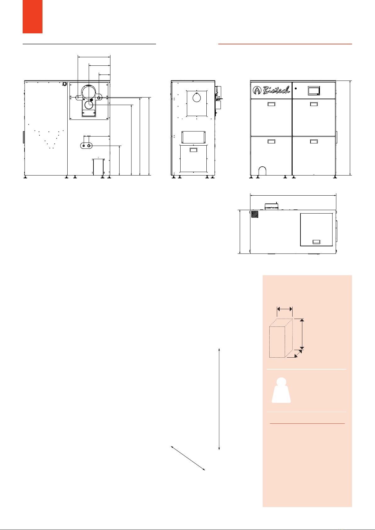
03 DIMENSONS
3.1 TOP LIGHT M
TOP LIGHT M
Pellet boiler
Insert dimensions
boiler (min.)
A : 610 mm
B : 1460 mm
C : 650 mm
Insert dimensions
container (min.)
A : 620 mm
B : 1550 mm
C : 670 mm
Boiler 204 kg
Container 66 kg
Cladding 62 kg
Ash box 15 kg*
All 332 kg
A
B
C
KG
1) with mounted ash discharge 1200 mm
2) Recommendation min. 250 mm, other-
wise increased maintenance eort (costs)
3) with automatic ash discharge min. 500
mm
Minimum distance masonry
1 : 900 mm 13 : 100-300 mm 2
2 : 400-900 mm 4 : 50-200 mm 3

1
1
2
2
3
3
4
4
5
5
6
6
7
7
8
8
A A
B B
C C
D D
E E
F F
A2
Status Änderungen Datum Name
Gezeichn.
Kontroll.
Norm
Datum Name
20.07.2021 PoSe
Biotech
Biotech Energietechnik GmbH
Plainfelder Straße 3
A-5303 Thalgau
TLM-MBW
AAllllggeemmeeiinnttoolleerraannzzeennnnaacchh::
Material:
Gewicht: 314,06 kg Fläche: 35769556,38 mm^2
M: 1 : 10
Oberfläche:
DIN ISO 2768-1/2 m/K EN ISO 9013-331 >10mm
EN ISO 9013-332 <10mm EN ISO 5817- D EN ISO 13920- BF
RReevv..
Blatt 1
UUnnbbeemmaaßßtteeWWeerrkkssttüücckkkkaanntteenn
nnaacchhÖÖNNoorrmmIISSOO1133771155
-0,5
-1
OObbeerrffllääcchhee
ISO 1302
DIN ISO 16016
1341
1435
320
488
65 420 125
75
667
1155
55
1402
1435
1341
1420
667
488
75
55
65 420
1155
320
125
4
3
2
1
min. 2000 mm
TOP LIGHT M MBW
Pellet boiler
Insert dimensions
boiler (min.)
A : 610 mm
B : 1460 mm
C : 650 mm
Insert dimensions
container (min.)
A : 620 mm
B : 1390 mm
C : 670 mm
Boiler 204 kg
Container 59 kg
Cladding 62 kg
Ash box 15 kg*
All 325 kg
A
B
C
KG
1) with mounted ash discharge 1200 mm
2) Recommendation min. 250 mm, other-
wise increased maintenance eort (costs)
3) with automatic ash discharge min. 500
mm
Minimum distance masonry
1 : 900 mm 13 : 100-300 mm 2
2 : 400-900 mm 4 : 50-200 mm 3
10
03 DIMENSIONS
3.2 TOP LIGHT M MBW

1
1
2
2
3
3
4
4
5
5
6
6
7
7
8
8
A A
B B
C C
D D
E E
F F
A2
Status Änderungen Datum Name
Gezeichn.
Kontroll.
Norm
Datum Name
20.07.2021 PoSe
Biotech
Biotech Energietechnik GmbH
Plainfelder Straße 3
A-5303 Thalgau
PZ-25 m. Turbine
AAllllggeemmeeiinnttoolleerraannzzeennnnaacchh::
Material:
Gewicht: 355,84 kg Fläche: 42439629,88 mm^2
M: 1 : 10
Oberfläche:
DIN ISO 2768-1/2 m/K EN ISO 9013-331 >10mm
EN ISO 9013-332 <10mm EN ISO 5817- D EN ISO 13920- BF
RReevv..
Blatt 1
UUnnbbeemmaaßßtteeWWeerrkkssttüücckkkkaanntteenn
nnaacchhÖÖNNoorrmmIISSOO1133771155
-0,5
-1
OObbeerrffllääcchhee
ISO 1302
DIN ISO 16016
1444
1644
323
78,5
452
1075
1180
1190
173
323
489
1305
667
1190
1180
1075
173
323
1305
667
489
1644
1444
452
32378,5
4
3
2
1
PZ25RL
Pellet boiler
Insert dimensions
boiler (min.)
A : 610 mm
B : 1400 mm
C : 720 mm
Insert dimensions
container (min.)
A : 740 mm
B : 1650 mm
C : 670 mm
Boiler 218 kg
Container 69 kg
Cladding 69 kg
Ash box 15 kg*
All 356 kg
A
B
C
KG
1) with mounted ash discharge 1200 mm
2) Recommendation min. 250 mm, other-
wise increased maintenance eort (costs)
Minimum distance masonry
1 : 900 mm 13 : 100-300 mm 2
2 : 400-900 mm 4 : 500-900 mm
10 11
03 DIMENSIONS
3.6 PZ25RL
min. 2200 mm
1
1
2
2
3
3
4
4
5
5
6
6
7
7
8
8
A A
B B
C C
D D
E E
F F
A2
Status Änderungen Datum Name
Gezeichn.
Kontroll.
Norm
Datum Name
20.07.2021 PoSe
Biotech
Biotech Energietechnik GmbH
Plainfelder Straße 3
A-5303 Thalgau
PZ-25 MBW
AAllllggeemmeeiinnttoolleerraannzzeennnnaacchh::
Material:
Gewicht: 342,75 kg Fläche: 39944106,50 mm^2
M: 1 : 10
Oberfläche:
DIN ISO 2768-1/2 m/K EN ISO 9013-331 >10mm
EN ISO 9013-332 <10mm EN ISO 5817- D EN ISO 13920- BF
RReevv..
Blatt 1
UUnnbbeemmaaßßtteeWWeerrkkssttüücckkkkaanntteenn
nnaacchhÖÖNNoorrmmIISSOO1133771155
-0,5
-1 OObbeerrffllääcchhee
ISO 1302
DIN ISO 16016
1444
323
78,5
452
1075
1180
1190
173
323
489
1305
667
1190
667
1444
489
1305
323
173
1180
1075
32378,5
452
4
3
2
1
PZ25RL MBW
Pellet boiler
Insert dimensions
boiler (min.)
A : 610 mm
B : 1400 mm
C : 720 mm
Insert dimensions
container (min.)
A : 740 mm
B : 1500 mm
C : 670 mm
Boiler 218 kg
Container 62 kg
Cladding 69 kg
Ash box 15 kg*
All 349 kg
A
B
C
KG
1) with mounted ash discharge 1200 mm
2) Recommendation min. 250 mm, other-
wise increased maintenance eort (costs)
Minimum distance masonry
1 : 900 mm 13 : 100-300 mm 2
2 : 400-900 mm 4 : 500-900 mm
12
03 DIMENSIONS
3.7 PZ25RL MBW
min. 2200 mm

1
1
2
2
3
3
4
4
5
5
6
6
7
7
8
8
A A
B B
C C
D D
E E
F F
A2
Status Änderungen Datum Name
Gezeichn.
Kontroll.
Norm
Datum Name
20.07.2021 PoSe
Biotech Biotech Energietechnik GmbH
Plainfelder Straße 3
A-5303 Thalgau
PZ-35 m. Turbine
AAllllggeemmeeiinnttoolleerraannzzeennnnaacchh::
Material:
Gewicht: 411,03 kg Fläche: 48189773,59 mm^2
M: 1 : 10
Oberfläche:
DIN ISO 2768-1/2 m/K EN ISO 9013-331 >10mm
EN ISO 9013-332 <10mm EN ISO 5817- D EN ISO 13920- BF
RReevv..
Blatt 1
UUnnbbeemmaaßßtteeWWeerrkkssttüücckkkkaanntteenn
nnaacchhÖÖNNoorrmmIISSOO1133771155
-0,5
-1
OObbeerrffllääcchhee
ISO 1302
DIN ISO 16016
452
323
78,5
1325,00
1425
1440
173,00
323
489
1894,00
1694,00
1305
667
452
489
1325
323
323
1425
173
1440
78,5
1694
1894
667
1305
4
3
2
1
PZ32/35RL
Pellet boiler
Insert dimensions
boiler (min.)
A : 610 mm
B : 1650 mm
C : 720 mm
Insert dimensions
container (min.)
A : 740 mm
B : 1880 mm
C : 670 mm
Boiler 258 kg
Container 78 kg
Cladding 75 kg
Ash box 15 kg*
All 411 kg
A
B
C
KG
1) with mounted ash discharge 1200 mm
2) Recommendation min. 250 mm, other-
wise increased maintenance eort (costs)
Minimum distance masonry
1 : 900 mm 13 : 100-300 mm 2
2 : 400-900 mm 4 : 500-900 mm
12 13
03 DIMENSIONS
3.8 PZ32/35RL
min. 2200 mm

1
1
2
2
3
3
4
4
5
5
6
6
7
7
8
8
A A
B B
C C
D D
E E
F F
A2
Status Änderungen Datum Name
Gezeichn.
Kontroll.
Norm
Datum Name
20.07.2021 PoSe
Biotech
Biotech Energietechnik GmbH
Plainfelder Straße 3
A-5303 Thalgau
PZ-35 MBW
AAllllggeemmeeiinnttoolleerraannzzeennnnaacchh::
Material:
Gewicht: 397,94 kg Fläche: 45694250,21 mm^2
M: 1 : 10
Oberfläche:
DIN ISO 2768-1/2 m/K EN ISO 9013-331 >10mm
EN ISO 9013-332 <10mm EN ISO 5817- D EN ISO 13920- BF
RReevv..
Blatt 1
UUnnbbeemmaaßßtteeWWeerrkkssttüücckkkkaanntteenn
nnaacchhÖÖNNoorrmmIISSOO1133771155
-0,5
-1
OObbeerrffllääcchhee
ISO 1302
DIN ISO 16016
323
78,5
452
1325
1425
1440
173
323
489
667
1305
1694
452
489
1325
323
323
1425
173
1440
78,5
1694
667
1305
4
3
2
1
PZ32/35RL MBW
Pellet boiler
Insert dimensions
boiler (min.)
A : 610 mm
B : 1650 mm
C : 720 mm
Insert dimensions
container (min.)
A : 740 mm
B : 1730 mm
C : 670 mm
Boiler 258 kg
Container 71 kg
Cladding 75 kg
Ash box 15 kg*
All 404 kg
A
B
C
KG
1) with mounted ash discharge 1200 mm
2) Recommendation min. 250 mm, other-
wise increased maintenance eort (costs)
Minimum distance masonry
1 : 900 mm 13 : 100-300 mm 2
2 : 400-900 mm 4 : 500-900 mm
14
03 DIMENSIONS
3.9 PZ32/35RL MBW
min. 2200 mm

A ( 1 : 10 )
A
1
1
2
2
3
3
4
4
5
5
6
6
7
7
8
8
A A
B B
C C
D D
E E
F F
A2
Status Änderungen Datum Name
Gezeichn.
Kontroll.
Norm
Datum Name
20.07.2021 PoSe
Biotech
Biotech Energietechnik GmbH
Plainfelder Straße 3
A-5303 Thalgau
PZ 45 m. Turbine
AAllllggeemmeeiinnttoolleerraannzzeennnnaacchh::
Material:
Gewicht: - Fläche: -
M: 1 : 10
Oberfläche:
DIN ISO 2768-1/2 m/K EN ISO 9013-331 >10mm
EN ISO 9013-332 <10mm EN ISO 5817- D EN ISO 13920- BF
RReevv..
Blatt 1
UUnnbbeemmaaßßtteeWWeerrkkssttüücckkkkaanntteenn
nnaacchhÖÖNNoorrmmIISSOO1133771155
-0,5
-1
OObbeerrffllääcchhee
ISO 1302
DIN ISO 16016
40
70
70 485
190
1235
1450
140 485
150
1944,00
1744,00
80
817
385
1505
1505
485
150
48570
70
140
817
1944
1744
1450
1235
190
40
385 80
4
3
2
1
PZ45/50/55RL
Pellet boiler
Insert dimensions
boiler (min.)
A : 800 mm
B : 1800 mm
C : 800 mm
Insert dimensions
container (min.)
A : 840 mm
B : 1950 mm
C : 820 mm
Boiler 324 kg
Container 84 kg
Cladding 95 kg
Ash box 15 kg*
All 503 kg
A
B
C
KG
Minimum distance masonry
1 : 1200 mm 3 : 700-900 mm
2 : 600-900 mm 4 : 700-900 mm
14 15
03 DIMENSIONS
3.10 PZ45/50/55RL
min. 2300 mm

1
1
2
2
3
3
4
4
5
5
6
6
7
7
8
8
9
9
10
10
11
11
12
12
A A
B B
C C
D D
E E
F F
G G
H H
A1
Status Änderungen Datum Name
Gezeichn.
Kontroll.
Norm
Datum Name
20.07.2021 PoSe
Biotech
Biotech Energiete chnik GmbH
Plainfelder Straße 3
A-5303 Thalgau
MBG PZ 65 m. Verkleidung
AAllllggeemmeeiinnttoolleerraannzzeennnnaacchh::
Material:
Gewicht: 808,89 kg Fläche: 101388280,38 mm^2
PZ 65
M: 1 : 8
PT-06-03-M01-03
L1010E090
Oberfläche:
DIN ISO 2768-1/2 m/K EN ISO 9013-331 >10mm
EN ISO 9013-332 <10mm EN ISO 5817- D EN ISO 13920- BF
RReevv..
Blatt 1
UUnnbbeemmaaßßtteeWWeerrkkssttüücckkkkaanntteenn
nnaacchhÖÖNNoorrmmIISSOO1133771155
-0,5
-1
OObbeerrffllääcchhee
ISO 1302
DIN ISO 16016
1246
1333
1794
1221
1210
1297
1733
140
1339
1744
1769
1820
1
1
2
2
3
3
4
4
5
5
6
6
7
7
8
8
9
9
10
10
11
11
12
12
A A
B B
C C
D D
E E
F F
G G
H H
A1
Status Änderungen Datum Name
Gezeichn.
Kontroll.
Norm
Datum Name
20.07.2021 PoSe
Biotech
Biotech Energiete chnik GmbH
Plainfelder Straße 3
A-5303 Thalgau
MBG PZ 65 m. Verkleidung
AAllllggeemmeeiinnttoolleerraannzzeennnnaacchh::
Material:
Gewicht: 808,89 kg Fläche: 101388280,38 mm^2
PZ 65
M: 1 : 8
PT-06-03-M01-03
L1010E090
Oberfläche:
DIN ISO 2768-1/2 m/K EN ISO 9013-331 >10mm
EN ISO 9013-332 <10mm EN ISO 5817- D EN ISO 13920- BF
RReevv..
Blatt 1
UUnnbbeemmaaßßtteeWWeerrkkssttüücckkkkaanntteenn
nnaacchhÖÖNNoorrmmIISSOO1133771155
-0,5
-1
OObbeerrffllääcchhee
ISO 1302
DIN ISO 16016
1246
1333
1794
1221
1210
1297
1733
140
1339
1744
1769
1820
1794
1733
1297
1210
140
1246
1221
1744
1333
1769
1820
1339
4
3
2
1
16
03 DIMENSIONS
3.11 PZ65/69RL
PZ65/69RL
Pellet boiler
Insert dimensions
boiler (min.)
A : 850 mm ¹
B : 1805 mm ²
C : 1280 mm
Insert dimensions
container (min.)
A : 740 mm
B : 1800 mm ²
C : 1260 mm
All 920 kg
A
B
C
Minimum distance masonry
1 : 200 mm 3 : 1200 mm
2 : 750 mm 4 : 700 mm
KG
min. 2300 mm

1
1
2
2
3
3
4
4
5
5
6
6
7
7
8
8
9
9
10
10
11
11
12
12
A A
B B
C C
D D
E E
F F
G G
H H
A1
Status Änderungen Datum Name
Gezeichn.
Kontroll.
Norm
Datum Name
20.07.2021 PoSe
Biotech
Biotech Energietechnik GmbH
Plainfelder Straße 3
A-5303 Thalgau
MBG PZ 65 m. Verkleidung
2.Var
AAllllggeemmeeiinnttoolleerraannzzeennnnaacchh::
Material:
Gewicht: 816,79 kg Fläche: 102925815,39 mm^2
PZ 80
M: 1 : 8
PT-06-03-M14-03
L1010E091
Oberfläche:
DIN ISO 2768-1/2 m/K EN ISO 9013-331 >10mm
EN ISO 9013-332 <10mm EN ISO 5817- D EN ISO 13920- BF
RReevv..
Blatt 1
UUnnbbeemmaaßßtteeWWeerrkkssttüücckkkkaanntteenn
nnaacchhÖÖNNoorrmmIISSOO1133771155
-0,5
-1
OObbeerrffllääcchhee
ISO 1302
DIN ISO 16016
1246
1333
1794
140
1210
1297
1733
1221
1769
1744
1339
1820
1
1
2
2
3
3
4
4
5
5
6
6
7
7
8
8
9
9
10
10
11
11
12
12
A A
B B
C C
D D
E E
F F
G G
H H
A1
Status Änderungen Dat um Name
Gezeichn.
Kontroll.
Norm
Datum Name
20.07.2021 PoSe
Biotech
Biotech Energietechnik GmbH
Plainfelder Straße 3
A-5303 Thalgau
MBG PZ 65 m. Verkleidung
2.Var
AAllllggeemmeeiinnttoolleerraannzzeennnnaacchh::
Material:
Gewicht: 816,79 kg Fläche: 102925815,39 mm ^2
PZ 80 M: 1 : 8
PT-06-03-M14-03
L1010E091
Oberfläche:
DIN ISO 2768-1/2 m/K EN ISO 9013-331 >10mm
EN ISO 9013-332 <10mm EN ISO 5817- D EN ISO 13920- BF
RReevv..
Blatt 1
UUnnbbeemmaaßßtteeWWeerrkkssttüücckkkkaanntteenn
nnaacchhÖÖNNoorrmmIISSOO1133771155
-0,5
-1 OObbeerrffllääcchhee
ISO 1302
DIN ISO 16016
1246
1333
1794
140
1210
1297
1733
1221
1769
1744
1339
1820
1794
1733
1297
140
1210
1246
1339
1333
1769
1820
1221
1744
4
3
2
1
16 17
03 DIMENSIONS
3.12 PZ80RL
PZ80RL
Pellet boiler
Insert dimensions
boiler (min.)
A : 850 mm ¹
B : 1805 mm ²
C : 1280 mm
Insert dimensions
container (min.)
A : 740 mm
B : 1800 mm ²
C : 1260 mm
All 920 kg
A
B
C
Minimum distance masonry
1 : 200 mm 3 : 1200 mm
2 : 750 mm 4 : 700 mm
KG
min. 2300 mm

1
1
2
2
3
3
4
4
5
5
6
6
7
7
8
8
9
9
10
10
11
11
12
12
A A
B B
C C
D D
E E
F F
G G
H H
A1
Status Änderungen Datum Name
Gezeichn.
Kontroll.
Norm
Datum Name
20.07.2021 PoSe
Biotech
Biotech Energiete chnik GmbH
Plainfelder Straße 3
A-5303 Thalgau
MBG PZ 100 mit Verkleidung
AAllllggeemmeeiinnttoolleerraannzzeennnnaacchh::
Material:
Gewicht: 355,25 kg Fläche: 82661081,11 mm^2
PZ 100 M: 1 : 8
PT-07-03-M01-02
L1010E735
Oberfläche:
DIN ISO 2768-1/2 m/K EN ISO 9013-331 >10mm
EN ISO 9013-332 <10mm EN ISO 5817- D EN ISO 13920- BF
RReevv..
Blatt 1
UUnnbbeemmaaßßtteeWWeerrkkssttüücckkkkaanntteenn
nnaacchhÖÖNNoorrmmIISSOO1133771155
-0,5
-1
OObbeerrffllääcchhee
ISO 1302
DIN ISO 16016
140
1458
1545
1220
1988
1491
1578
2045
1745
1339
2068
2020
1
1
2
2
3
3
4
4
5
5
6
6
7
7
8
8
9
9
10
10
11
11
12
12
A A
B B
C C
D D
E E
F F
G G
H H
A1
Status Änderungen Datum Name
Gezeichn.
Kontroll.
Norm
Datum Name
20.07.2021 PoSe
Biotech
Biotech Energietechnik GmbH
Plainfelder Straße 3
A-5303 Thalgau
MBG PZ 100 mit Verkleidung
AAllllggeemmeeiinnttoolleerraannzzeennnnaacchh::
Material:
Gewicht: 355,25 kg Fläche: 82661081,11 mm^2
PZ 100
M: 1 : 8
PT-07-03-M01-02
L1010E735
Oberfläche:
DIN ISO 2768-1/2 m/K EN ISO 9013-331 >10mm
EN ISO 9013-332 <10mm EN ISO 5817- D EN ISO 13920- BF
RReevv..
Blatt 1
UUnnbbeemmaaßßtteeWWeerrkkssttüücckkkkaanntteenn
nnaacchhÖÖNNoorrmmIISSOO1133771155
-0,5
-1
OObbeerrffllääcchhee
ISO 1302
DIN ISO 16016
140
1458
1545
1220
1988
1491
1578
2045
1745
1339
2068
2020
2045
1988
1545
1458
1491
1578
2020
2068
1339
140
1220
1745
4
3
2
1
18
03 ABMESSUNGEN
3.13 PZ90/100/101RL
PZ90/100/101RL
Pellet boiler
Insert dimensions
boiler (min.)
A : 850 mm ¹
B : 1992 mm ²
C : 1280 mm
Insert dimensions
container (min.)
A : 740 mm
B : 2030 mm ²
C : 1260 mm
All 1160 kg
A
B
C
Minimum distance masonry
1 : 200 mm 3 : 1200 mm
2 : 750 mm 4 : 700 mm
KG
mind. 2300 mm

A4
Status Änderungen Datum Name
Gezeichn.
Kontroll.
Norm
Datum Name
22.07.2021 PoSe
Biotech
Biotech Energietechnik GmbH
Plainfelder Straße 3
A-5303 Thalgau
AAllllggeemmeeiinnttoolleerraannzzeennnnaacchh::
Material:
Gewicht: 2105,59 kg Fläche: 64931164,42 mm^2
M: 1 : 17
Oberfläche:
DIN ISO 2768-1/2 m/K EN ISO 9013-331 >10mm
EN ISO 9013-332 <10mm EN ISO 5817- D EN ISO 13920- BF
RReevv..
Blatt 1
UUnnbbeemmaaßßtteeWWeerrkkssttüücckkkkaanntteenn
nnaacchhÖÖNNoorrmmIISSOO1133771155
-0,5
-1
OObbeerrffllääcchhee
ISO 1302
DIN ISO 16016
130-140 mm
600
All dimensions in mm!
18 19
REQUIREMENTS FOR THE FLUE PIPE
• Connect the flue pipe to the chimney at an angle
of at least 10°, ideally 30 to 45°.
• The exhaust pipe must not be reduced, the
diameter of the exhaust pipe must correspond to
that of the exhaust connection.
• The flue pipe must be pressure-tight and fitted with
thermal insulation at least 25 mm thick over its
entire length.
• The draught regulator must be installed at least
600 mm below the flue pipe inlet in the flue
system.
ATTENTION: If the chimney draught regulator is
installed directly in the flue pipe, contrary to the location
suggested below, due to the situation on site, an
increased dust load in the boiler room must be expected
- PLEASE take this into account when planning!
A moisture-resistant (FU) chimney (material 1.4401 or 1.4404 recommended) with a maximum flue draught of 10 Pa (0.10
mbar) is required. The connecting pipe (flue gas pipe) must be laid with a minimum gradient of 10° (30-45° is optimal)
with a maximum length of 3.0 metres. The flue pipe must be insulated with at least 25 mm. If possible, make the flue
connection with 45° bends. A connection with 90° bends can cause flue gas problems. The flue pipe must be connected
to the chimney in such a way that no condensation water can flow into the boiler. The boiler and the chimney must be
matched to each other (see chimney recommendation). EN 13384-1 must be used as a calculation aid.
The eective height is the flue length between the flue gas inlet into the flue and the flue mouth.The flue must be
adapted to the local, legal regulations! Low-emission operation according to the quality seal is only guaranteed if the
system can be operated with the low flue gas temperatures of the smallest heat output (30% of the nominal load).
This usually requires an acid-proof chimney.
It must be ensured that the return temperature does not fall below 55°C under any circumstances.
Since this cannot be guaranteed without an automatic return flow increase, it is mandatory to install
one! Failure to comply will invalidate the warranty.
04 CHIMNEY SPECIFICATION
05 RETURN FLOW BOOST
4.1 EFFECTIVE HEIGHT
ATTENTON!
The chimney must be insensitive to moisture (FU)!
The installation of a draught regulator is required.
A chimney calculation according to standard EN
13384-1 is required! See page 7 & 8 for data.
600
130-140

Filling nozzle
House junction box
max. 30 m
Pellet storage room Heating room
20
The pellets are delivered by a silo truck and blown into the storage room. The silo truck usually has a pump
hose with a maximum length of 30 running metres. length. The pellet storage room or the filling couplings may
therefore be a maximum of 30 running metres from the unloading point of the truck. If longer pump hoses are
necessary, clarify this with your pellet supplier. The longer the pipe is chosen, the more the quality of the pellets
is aected. This can lead to a situation where the fuel in the storage room no longer meets the requirements. If
possible, the pellet storage room should be adjacent
to an outside wall, as the filling spouts should be
accessible from the outside. The masonry must not
have any moisture under any circumstances! If the
storage room is inside, the blow-in and exhaust air
connections can be extended to the outside wall, or
the pellet supplier‘s pump hose can be laid through the
house during filling.
If possible, the boiler room should also be adjacent to an outside wall to ensure a direct combustion air supply to
the pellet heating system. If the boiler room is inside, a supply air duct must be led from the boiler room to the
outside wall (FeuVO). Country-specific regulations must be observed.
06 PELLET STORAGE ROOM
6.1 POSITION OF THE BOILER ROOM
ATTENTION!
Switch o the heating before filling the pellet store!
Please note that longer pipes lead to increased
abrasion (loss of quality).
This manual suits for next models
18
Table of contents
Other Biotech Boiler manuals


Popular Boiler manuals by other brands

Vaillant
Vaillant ecoTEC exclusive 843 Installation and maintenance instructions

Potterton
Potterton 40eL user guide

DeDietrich
DeDietrich MCA 45 user guide

Gruppo Imar
Gruppo Imar Gimax 25 Installation, commissioning, use and maintenance manual

Indol
Indol Supreme 200SA++ quick start guide

Viessmann
Viessmann VITORONDENS 200-T Service instructions

New Yorker
New Yorker AP-U SERIES Installation, operation and service instructions

First Choice
First Choice Zip Hydroboil Plus manual

Hamworthy
Hamworthy PUREWELL VariHeat c Instructions for use

Biasi
Biasi RIVA COMBI Service manual

Ferroli
Ferroli ECOUNIT 1C 200 manual

Traid
Traid TRIUMPH SS SERIES Operating and maintenance manual


