Bircher UniScan Y cable User manual

UniScan Y-Kabel
Beachten Sie die UniScan-Betriebsanleitung!
Montage
1
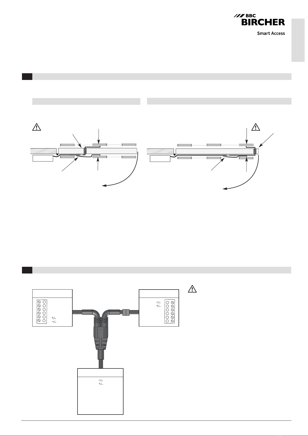
1. Nach der beidseitigen Positionierung der UniScans, Kabeldurchführung (Loch Ø 10 mm) für das
Verbindungskabel bohren. Kabeldurchführung in der Nähe des Mastermoduls platzieren (gem. Skizze oben).
Achtung: Länge Verbindungskabel beachten! Beachten Sie die länderspezifischen Brand-
und Rauchschutzbestimmungen! Der 6-polige Stecker passt durch eine 10 mm Bohrung. Dadurch ergibt sich
eine reine Stecklösung, keine Demontage erforderlich. Bei kleineren Lochdurchmessern zunächst
Steckschraubklemme demontieren, Kabel (Ø 4.5 mm) durchziehen, Steckschraubklemme erneut montieren.
Achtung: Klemmenbelegung bei der Remontage beachten!
2. Y-Kabel und Kabelstück zusammenstecken.
3. Verbindungskabel (Ø 5.5 mm) an Türsteuerung anschliessen.
4. Nach der Montage und Verkabelung der Sensoren müssen die Initialisierung am Mastermodul auf der
Bandseite und Bandgegenseite erfolgen (5 sec «grüne» Taste drücken).
Seite B:
typ. Bandgegenseite
Seite B:
typ. Bandgegenseite
Y-Kabel
Platzierung
Kabel-
durchführung
Mastermodul
Mastermodul
Mastermodul
Türe von oben
Kabeldurchführung in Tür-Mitte Kabeldurchführung auf der Tür-Seite
Die Positionierung des Y-Kabels sowie der Kabeldurchführung ist entsprechend der Gegebenheiten zu wählen (siehe folgende Skizzen).
Y-Kabel
Platzierung
Kabel-
durchführung
Mastermodul
Türe von oben
Wenn die Bohrung in der Tür-Mitte nicht möglich ist (zum Beispiel bei Glastüren),
wird empfohlen, die Kabeldurchführung auf der Tür-Seite zu wählen.
Steuerung
BBC Bircher Smart Access, BBC Bircher AG, Wiesengasse 20, CH-8222 Beringen, www.bircher.com
Steuerung
3 m
weiss
braun
grün
gelb
rosa
grau
blau
rot
violett
COM
NO
NC
Test
COM
NO
NC
Band-
seite A
Band-
gegen-
seite B
쐰
쐰
USbeam USbeam
weiss
braun
grau
grün
rosa
gelb
COM
NC
NO
test
1
2
3
4
5
6
6
5
4
3
2 braun
weiss
1
COM grau
NC grün
NO rosa
Test gelb
0.45 m
0.90 m
Ø 10 mm
Ø 5.5 mm
Ø 4.5 mm
Ø 4.5 mm
Steuerung
Seite A:
typ. Bandseite
Seite A:
typ. Bandseite
DE EN
296574F
10/19
Anschluss
2
Standard:
NO (normaly open)
angeschlossen,
Relaisausgang auf passive
Schaltung.
Die US beams, welche direkt mit dem Y-Kabel verbunden
werden, werden jeweils als Mastermodul bezeichnet. Alle
weiteren US beams werden mit dem Flachbandkabel
verbunden und sind slaves. Pro US beam-Mastermodul
dürfen max. drei weitere US beams angeschlossen werden.
Bei Wechselspannungsversorgung können die Sensoren
nicht durch das Flachbandkabel verbunden (kaskadiert)
werden.
Bei Verwendung des UniScans als Sicherheitssensor
muss die Testung richtig angeschlossen werden!
Seite A:
typ. Bandseite
Seite B:
typ. Bandgegenseite
Bei Stromausfall fällt Kontakt
ab, damit die Tür in einen
sicheren Zustand geht
(Tür offen).
DE EN
296574F
10/19
Controller
3 m
white
brown
green
yellow
pink
grey
blue
red
purple
COM
NO
NC
test
COM
NO
NC
Hinge
side A
Non-hinge
side B
쐰
쐰
USbeam USbeam
white
brown
grey
green
pink
yellow
COM
NC
NO
test
1
2
3
4
5
6
6
5
4
3
2 brown
white
1
COM grey
NC green
NO pink
test yellow
0.45 m
0.90 m
Ø 10 mm
Ø 5.5 mm
Ø 4.5 mm
Ø 4.5 mm
Controller
Y cable Master module
Door from above
UniScan Y cable
Comply with the UniScan operating instructions!
Mounting
1
1. After having attached the UniScans on both sides, drill a hole (Ø 10 mm) for feeding through the connection
cable. Position the cable feed-through in the vicinity of the master module (acc. to diagram above).
Caution: Observe length of connection cable!
Comply with the country-specific fire and smoke prevention regulations!
The 6-pin plug fits through a 10 mm hole. This results in a pure plug-in connection; no dismantling required.
In case of smaller hole diameters, first remove the plug-in screw terminal, then pull the cable (Ø 4.5 mm) through and
remount the plug-in screw terminal.
Caution: Observe the terminal assignment during remounting!
2. Connect Y cable and non-hinge side cable together.
3. Connect connection cable (Ø 5.5 mm) to door controller.
4. After the sensors have been installed and wired, they must be initialised at the master module on the hinge
side and the non-hinge side (press <<green>> button for 5 seconds).
Cable feed-through in door middle Cable feed-through on door side
The position of the Y cable and the cable feed-through must be chosen according to the local conditions (see the following diagrams).
Positioning of
cable feed-through
Master module
If it is not possible to drill a hole in the door middle (for example with glass doors),
we recommend choosing a cable feed-through location on the side of the door.
Connection
2
If AC voltage is supplied, only single sensor operation
is possible and it is not allowed to cascade the sensors
by ribbon cable. When the UniScan is used as a safety
sensor, the testsignal must be connected.
BBC Bircher Smart Access, BBC Bircher AG, Wiesengasse 20, CH-8222 Beringen, www.bircher.com
Side B:
typ. non-hinge side
Side B:
typ. non-hinge side
Side A:
typ. hinge side
Side A:
typ. hinge side
Controller
Y cable
Positioning of
cable feed-through
Master module
Master module
Door from above
Standard
NO (normaly open) connected,
relay output to passive circuit.
The US beams that are connected directly to the Y cable are
referred to as master modules. All other US beams are connec-
ted with the ribbon cable and are slaves. Per US beam master
module, a maximum of three other US beams may be connected.
In case of a power failure,
the contact falls open
so that the door goes into a
safe state (door open).
Side A:
typ. hinge side
Side B:
typ. non-hinge side
Table of contents
Languages:


