ELEY 1041 Programming manual

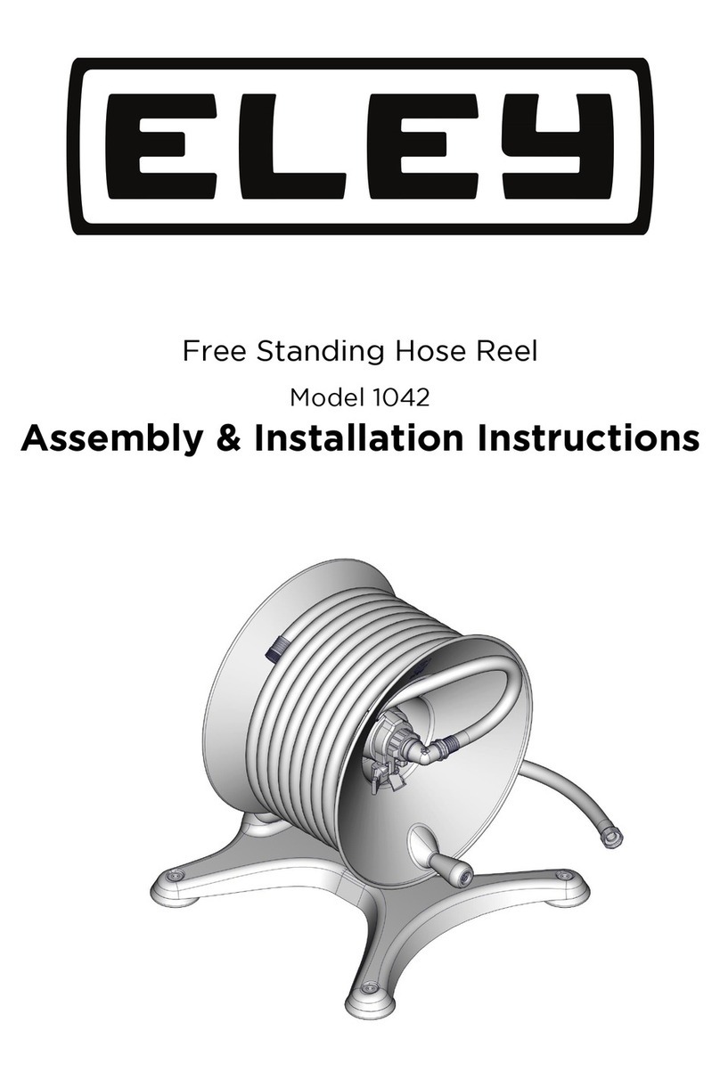
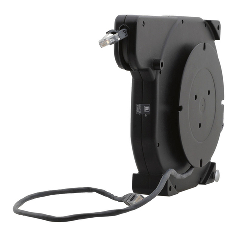
Wall Mount Garden Hose Reel
Model 1041
Assembly & Installation Instructions

Page 2
Reel Specications
Max. Temperature....140° F (60° C)
Max. Pressure.............150 PSI (10 Bar)
CONTENTS
Please DO NOT contact or return this
item to the retailer. Seek assistance
directly from ELEY Corporaon using
the informaon below.
PHONE:
1-866-523-2363 (toll free)
MON- FRI, 8am to 5pm (CST)
E-MAIL:
MON- FRI, 8am to 5pm (CST)
ONLINE:
The SUPPORT secon on our website
www.eleyhosereels.com is available
24/7/365 and contains assembly
videos, repair instrucons and FAQ’s.
QUESTIONS?
PROBLEMS?
123
4 5 6
7
89
10
11
12
13 14
15
10 16
17

Page 3
STEP 1
Place the Front
Flange (4027) on
top of the Back
Flange (4028).
Pins and sockets on
the anges will aid in
proper alignment.
IMPORTANT!
If you purchased an Extra-Capacity Kit
(Item# 1044) with your reel, please refer
to the assembly instructions included
with the Extra-Capacity Kit now. When
you have completed those instructions,
then proceed to Step 3 of this manual.
Standard Reel
Upgraded with
Extra-Capacity Kit

Page 4
STEP 2
Fasten anges together using the three
M6 x 20 Hex Socket Head Cap Screws
(4006) and the small hex end of the
Hex Key Wrench (4003).
STEP 3
Remove the screw from the
Handle Assembly (2654).
STEP 4
Install Handle Assembly
into Front Flange.

Page 5
STEP 5
Remove the two M10 x 25 Hex Socket Head Cap Screws
(4013) and 3/8” Flat Washers (2520) from the Garden
Hose Reel Arm (3071).
STEP 6
Determine which direction you want the reel to operate.
Parallel Perpendicular
STEP 7
Attach the Garden Hose Reel Arm (3071) securely to the Wall Mount Base (2558) using the two
previously removed M10 x 25 Hex Socket Head Cap Screws (4013) and 3/8” Flat Washers (2520).
Parallel Perpendicular

Page 6
Parallel Perpendicular
Step 8
Locate the reel base within 5 feet of your faucet. Note: Be certain there are no other
objects that may interfere with the proper operation of your reel.
Installation Option A - Masonry Walls
(For Option B, stud-wall installation, skip ahead to page 8)
Parallel Perpendicular
Step A9
Use a marker or pencil to mark the location of the four mounting holes on your wall.

Page 7
Step A10
Use a 5/16 inch masonry
bit (not included) and drill
1-1/2 inch deep holes at
the 4 marked locations.
Helpful hints:
Measure and then mark
the masonry bit with
masking tape to ensure
you drill at the proper
depth. Clean the holes
with a shop vacuum.
Wear eye and dust
protection.
Step A11
Position the Wall Mounting Base over the drilled holes and tap the four 5/16” x 1-3/4” Sleeve
Anchor Bolts (2598) through the base and into the holes in the wall.
Step A12
Tighten the four sleeve anchor bolts with a 7/16 inch wrench. Do not over tighten.
PerpendicularParallel
PerpendicularParallel
Proceed to step 13
on page 10.

Page 9
Installation Option B - Stud Walls
Parallel Perpendicular
Step B10
Use a 1/8 inch drill bit (not included) and drill 1-1/2 inch deep holes at the four marked locations.
Helpful hint: Measure and then mark the drill bit with masking tape to ensure you drill at the
proper depth. Wear eye protection.
Step B9
Use a marker or pencil to mark the location of the four mounting holes on your wall.
Note: Locate studs prior to drilling. The reel must be fastened to 2 studs.
Page 8

Perpendicular
Step B12
Tighten the four 1/4 x 2-1/2 inch Hex Head Lag Screws (2319) with a 7/16 inch wrench.
Do not over tighten.
Page 9
Perpendicular
Parallel
Step B11
If you are fastening to lap siding, use the four Standoffs (2510) between the Wall Mounting base
and the siding. Fasten the base to the wall with the four 1/4 x 2-1/2 inch Hex Head Lag Screws
(2319) and 1/4 inch Flat Washers (2331).
Parallel

Page 10
PerpendicularParallel
Step 13 - Insert the externally threaded (male) end of the Inlet hose (1087) into the axle tube
until it is accessible from the other side.
Step 14 - Install the Flange Assembly onto the axle with the crank handle to the outside.
Step 15 - Install the Cam-lever Brake (2587) onto the axle.
Note: Align the tab on the brake with the notch in the ange.
PerpendicularParallel
PerpendicularParallel

Page 11
Step 16
Attach the Swivel (2914) to the inlet hose.
Step 17 - Attach the Swivel to the axle. Hand tighten rmly.
Parallel Perpendicular
Parallel Perpendicular

Step 18
Position the Hose Strap
(4045) 32 inches from the
internally threaded (Female)
end of your garden hose.
Page 12
Step 19
Position the Hose Strap
(4045) so the grommets
pass through the small slot
in the ange.

Step 22
Hand tighten your
garden hose to the
brass swivel.
Page 13
Step 20
Tighten the hose
strap. The M6 x 65
Hex Socket Head
Cap Screw (4009)
will pass through the
1/4 inch Flat Washer
(2331) and the two
brass grommets on
the hose strap and
then thread into the
cage nut on the reel
ange assembly.
Do not over tighten.
Step 21
Insert your garden
hose through the
large opening in
the reel ange.
Install the Anti-Kink
Spring (2367) into
the end of your
hose. The small end
rst.

Page 14
How to use the Cam-Lever Brake
As you pull the hose from the reel, our innovative cam-lever brake will
prevent the reel from “free-spinning”, unrolling more hose than you
want. The brake can be turned ON and OFF with the ick of the lever.
BRAKE ON
Pulling the hose out.
BRAKE OFF
Reeling the hose in.

Page 15
How to adjust the Cam-Lever Brake
1. Place the cam-lever in the “ON” position.
2. Pull enough hose off the reel to test the amount of drag created by the Cam-Lever Brake.
a. Too little drag, and the reel will continue to unspool hose after you’ve stop pulling.
i. Tighten the nut on the Cam-Lever Brake using a 3/8” wrench.
ii. Adjust 1/4 turn of the wrench.
ii. Test again.
b. Too much drag and it will be difcult to pull hose off the reel.
i. Loosen the nut on the Cam-Lever Brake using a 3/8” wrench.
ii. Adjust 1/4 turn of the wrench.
ii. Test again.

©2014 Eley Corporation PO Box 22640 Lincoln, NE 68542-2640 Rev. 04/14
Patents and Patents Pending (Manual Part # 4074)
Model: 1041 Serial # ____________________
Purchase Date:_________________________________
Purchased From:________________________________
10 Year Warranty
Coverage
Eley Corporation guarantees this hose reel, components and parts, unless otherwise specied,
to be free from defect, malfunction or failure in material, or workmanship, under normal use
and service, for a period of 10 years(120 months). Warranty period starts from original invoice
date. In the event of a defect or component failure, Eley Corporation will replace the specic
component(s) free of charge.
Exemptions
Warranty does not cover leaking due to damage caused by the use of acid, harsh chemicals
or mineral deposits. Warranty does not apply when products are used in excess of their
rated capacities and design functions or under abnormal conditions. The effects of corrosion,
and normal wear and tear are specically excluded from this warranty. This warranty does
not cover damage which occurs in shipment or failures which are caused by products
not supplied by the warrantor or failures which result from accidents, mishandling, faulty
installation, freezing, misuse or misapplication, abuse or neglect. Warranty is void if the
product or any part thereof has been tampered or altered in any manner, or damage that is
attributable to acts of God. Eley Corporation covers the replacement or credit of defective
parts only and does not allow for eld labor charges for removal, installation, analysis or
travel expenses. In no event shall Eley Corporation or its suppliers be liable for any damages,
whatsoever, arising out of the use of or inability to use this product. (Some states do not
allow the exclusion of limitation of incidental or consequential damages, so the above
limitation or exclusion may not apply to you). Eley Corporation and its suppliers disclaim all
other expressed or implied warranties. Some states do not allow limitations on how long an
implied warranty lasts, so the above limitation may not apply to you. This warranty gives you
specic legal rights, and you may also have other rights which vary from state to state.
Other manuals for 1041
1
Table of contents
Other ELEY Cables And Connectors manuals
Popular Cables And Connectors manuals by other brands

Cooper Lighting
Cooper Lighting Halo Lazer Track Lighting LZR211 installation instructions
Reelworks
Reelworks SR101.01 instruction manual
Staubli
Staubli CombiTac uniq CT-GOF Assembly instructions
Fischer Connectors
Fischer Connectors FOH Assembly instruction

Redarc
Redarc SRC0001 manual
Philips
Philips SWV3104S/10 user manual
