Bircher RFGate 2.2.NG Wiring diagram
1
12 3 4 5
ON
+
2032
175
189
138
50.8
10.8
4.8
175
189
50.8
138
10.8
4.8
178
80
121
162
12 3 4 5
ON
+
2032
+
2032
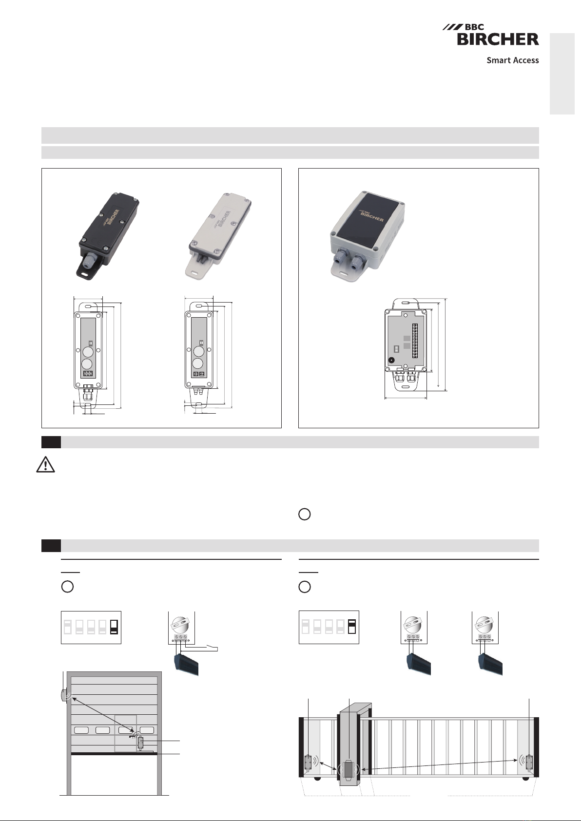
RFGate 2.2.A
RFGate 2.2.NG
Wireless signal transmission system for safety edges, two channels
Translation of original operating instructions
General
1Safety instructions
2Common application
2.1 Industrial door
ENGLISH
341032D
01/19
Transmitter Receiver
Warning: Switch off the operating voltage before working on the
system. Only trained, qualied personnel may perform installation
and startup. The unit may only be repaired by the manufacturer. The
switching unit may only be used to protect against dangers on
crushing and shearing points and on automatic industrial doors and
gates (intended use). National and international regulations on
industrial door and gate safety must be complied with. Always
Transmitter
Receiver
Safety edges
Safety edges
Receiver
Transmitter Transmitter 1 Transmitter 2
DIP switch 5 OFF
Transmitter 2 Transmitter 1
Safety edges
8.2 kΩ
Contact
(wicket door)
consider the safety functions of your application as a whole, never just in
relation to one individual section of the system. The installer is responsible
for carrying out a risk assessment and installing the industrial door system
correctly.
It is recommended to change the batteries every year.
ReceiverReceiver
Safety edges
8.2kΩ
Safety edges
8.2kΩ
DIP switch 5 ON
2.2 Site entrance gate
Transmitter input 1 corresponds to receiver output 1
Transmitter input 2 corresponds to receiver output 2
i
Transmitter 1 input 1 corresponds to receiver output 1
Transmitter 2 input 1 corresponds to receiver output 2
i
i
2
1 2
ON
1 2
ON
1 2
ON
1 2
ON
IN 1
NC 2x
8K28K2 8K28K2
i
NC
1
ON
1 2
+
2032
2
ON
1 2
+
+
2032
2032
8K2 8K2 1) 1)
IN 2 2)
8K2 1) 1) 8K2
VCC1
VCC2
COM1
OUT1
SOUT1
COM2
OUT2
SOUT2
TST1
COM.T1
TST2
COM.T2
+/~ –/~
12/24V
AC/DC
COM1
OUT1
COM2
OUT2
COM1
SOUT1
COM2
SOUT2
COM1
OUT1
COM2
OUT2
IN1
comon
IN2 2)
DIP switch Sensor
connections
IN1
comon
IN2 2)
DIP switch Sensor
connections
IN1
comon
IN2 2)
DIP switch Sensor
connections
IN1
comon
IN2 2)
DIP switch Sensor
connections
1) Change from NC to NO, see chapter 3.2
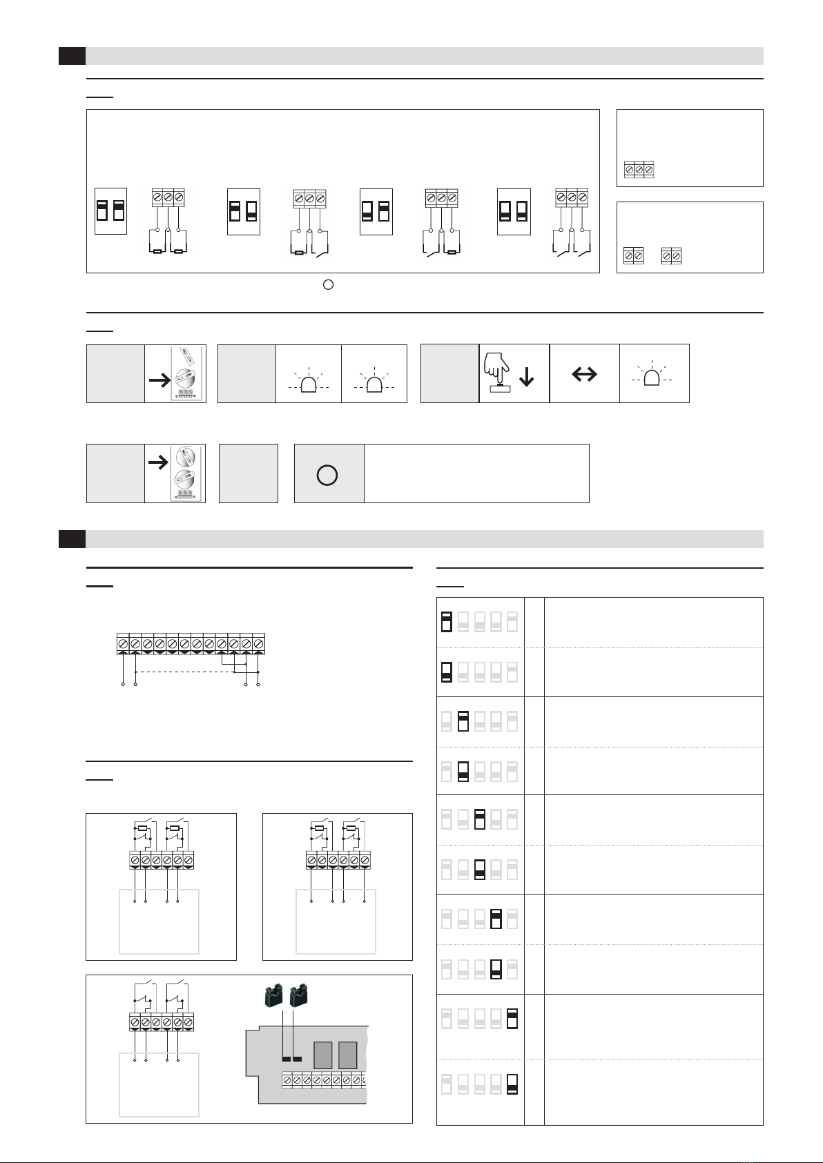
3.2 Change input from NC to NO (factory setting = NC)
4.3 DIP switches
3.1 DIP switch setting according to sensor (safety edge, switch contact)
4Receiver
3Transmitter
1.
Insert
battery 1
4.
Insert
battery 2
2.
Status
3.
Change
5.
Change
stored
Press button on
transmitter
Status
changes
LED
ashes
LED
ashes 2x
LED
ashes 5x
> 1.5 sec.
After inserting the battery 1,
you have 10 seconds to change the logic
1 2 3 4 5
ON *Safety application
standard
according to EN ISO 13849-1
1 2 3 4 5
ON inactive ➔no safety function!
(Radio connection is not monitored)
12 3 4 5
ON Transmission frequency
869.85 MHz: Set DIP-switch before pairing
transmitter – receiver
12 3 4 5
ON *868.95 MHz: Set DIP-switch before pairing
transmitter – receiver
12 34 5
ON Test input type
NC
activated = contact open
12 34 5
ON *NO
activated = contact closed
12 3 45
ON Automatic frequency adjustment
active
used only in case of radio disturbances
12 3 45
ON *inactive
12 3 4 5
ON *Programming of RF Gate 2.2.A
(2 transmitters)
Transmitter 1 corresponds to output 1
Transmitter 2 corresponds to output 2
12 3 4 5
ON Programming of RF Gate 2.2.NG
(1 transmitter)
Input 1 corresponds to output 1
Input 2 corresponds to output 2
*= factory setting
Observe
the sequence
IN1
comon
IN2 2)
RFGate 2.2.SRFGate 2.2.S
RFGate 2.2.S.F
Relay contacts are shown unpowered
4.2 Wiring: Outputs and control
Test
Common
Gate control
with
NC input
Gate control
8.2 kOhm
input
Gate control
with
NO input
Remove jumper(s)
4.1 Wiring: Power supply and test inputs
Common
both for IN1 and
IN2
2)
i
Input IN2 and DIP switch 2 only active at RFGate 2.2.NG (see paragraph 4.3, DIP switch 5)
NO 5x
NO
3
1
2
ON
1 2
+
+
2032
2032
ON
1 2
+
2032
1 2
ON
i
ON
OK?
12 3 4 5
ON
2x
i
1 2 3 4 5
ON
12 3 4 5
ON
2x
2x
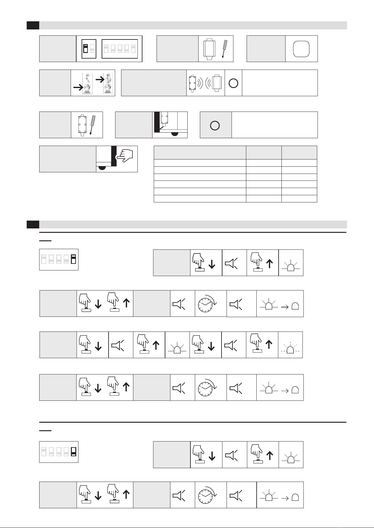
6.2. RFGate 2.2.NG, pairing transmitter with receiver
5Start-up
6Programming
2.
On the
transmitter
Press and
release button
Beep Wait 2
beeps
10 sec.
1.
On the receiver
Press
button
Beep
> 1.5 sec.
LED
lights up
6.
Transmitter:
install
Release
button
4.
Transmitter:
insert
batteries
1.
Check DIP
switch settings
5.
Programming (Chapter 6.1):
pair transmitter with receiver
The distance between transmitter
and receiver and further trans-
mitters must be at least 1 m
Observe
order
Code saved
LED goes out
Please observe the torque when
fastening the cover:
Max. 45 N cm
7.
Transmitter:
wire
3.
Turn on power
supply
2.
Install and wire
receiver
8.
System test of safety
edge on gate
6.1 RFGate 2.2.A, pairing transmitter with receiver
2.
On the trans-
mitter for
channel 1
On the
receiver
On the
receiver
On the
receiver
Press and
release button
Beep Wait 2
beeps
10 sec.
4.
On the trans-
mitter for
channel 2
Press and
release button
Beep Wait
10 sec.
3.
On the receiver
Beep BeepRelease
button
Release
button
LED
lights up
LED
ashes
Press
button
> 1,5 sec.
Press
button
> 1.5 sec.
1.
On the receiver
Press
button
Beep
> 1.5 sec.
LED
lights up
Release
button
2
beeps
Code saved
LED goes out
Code saved
LED goes out
Beep
Beep
Beep Beep
Beep
Beep Beep
Beep
BeepBeep
Status Terminals
COMx – OUTx
Terminals
COMx – SOUTx
Sensor not activated (operating mode) 8K2 closed
Sensor activated (security system activated) closed open
No supply voltage closed open
Transmitter and receiver not paired closed open
Broken cable between sensor and transmitter closed open
Transmitter batteries low closed open

4
12345
ON SAB
SELECT
REL 1 REL21
R2R1
1 2
2x
4x
Designed in Switzerland / Made in EU
BBC Bircher Smart Access, BBC Bircher AG, Wiesengasse 20, CH-8222 Beringen, www.bircher.com
7Standard operation
8Technical data
7.1 Receiver LED indicators 7.2 Warning indicator for low battery voltage
Object
detected
LED off
LED
Receiver: Signal sounds at each activation
Safety
OK
LED on
Battery voltage
low
6.3 Transmitter reset
6.4 Memory full
Press
button
Keep pressed
the button
Short beepsBeep WaitRelease
button
10 sec.
> 1.5 sec. > 3 sec.
2
beeps
Beep 10 sec.
Receiver
Supply voltage 12/24 V ACDC
Transmitter memory 7 + 7 (RFGate 2.2.A), 7 (RFGate 2.2.NG)
Output 2 relays 24 V, 0.5 A; micro switch-off 1B
Power consumption 0.5 W @ 12 V; 1.2 W @ 24 V
Test signal input 12/24 VACDC
Transmitter
Battery power 2 x Lithium 3 V Type CR2032
Power consumption Transmitting: 17 mA standby: 16 µA
System
Frequency bands 868.95 MHz & 869.85 MHz
Range under optimum conditions up to 100 m
Protection class IEC
60529
IP55
Pollution degree 2
Working temperature -20 °C to +55 °C
On
the
receiver
Memory cleared
on all
transmitters
Beep
Beep
Beep Beep Beep Beep
9EU Declaration of Conformity
11 Contact
See attachment
10 WEEE
Devices with this symbol must be treated separately during disposal. This must be done in accordance with the laws of
the respective countries for environmentally sound disposal, processing and recycling of electrical and electronic equipment.
See attachment
This manual suits for next models
1
Popular Receiver manuals by other brands

Onkyo
Onkyo TX-NR818 instruction manual

Pioneer
Pioneer VSX-45TX Elite Documentation update

DREAM MULTIMEDIA
DREAM MULTIMEDIA DM8000 HD PVR DVD Menu overview

Comfort Contego
Comfort Contego T800 user manual

PCB Piezotronics
PCB Piezotronics HT352A21 Installation and operating manual

Furuno
Furuno MF/HF DSC/Watch Receiver DSC-60 Specifications


 Service manual")


