Trikdis RI-4010M User manual

JOINT STOCK COMPANY
MULTICHANNEL RECEIVER RI-4010M (version RM1- 0 19)
User guide

Safety requirements
Before using the multichannel receiver RI-4010M read this user guide
and follows safety requirements!
The multichannel receiver RI-4010M is in continuous mode operating part of the
security system. It is supplied with power from AC network. In order to avoid injuries
(concerning heat or high voltage impact) or seeking to ensure reliable and long lasting
operation of the device it is necessary to follow safety requirements.
The multichannel receiver operates being in horizontal position only.
Digital LCD monitor of the multichannel receiver displays content of received
messages. Light emitting diodes of the receiver mean:
-Lighting green – power supplied, the device works from AC network;
-Lighting red – power supplied, the device works from backup 12 V battery
Only trained staff being aware of operation of used devices and safety
requirements can perform mounting and maintenance of the receiver.
The RI-4010M multichannel receiver is supplied with power from nominal 220 V
voltage of AC (50±1) Hz frequency network and from 12 V backup battery, capacitance
of which 7Ah. Permissible voltage alteration range is ±10%. Current from the network
does not exceed 0, 15 A. The receiver may be plugged in to circuits of AC network
(sockets).
Upon operation of safety fuse, the receiver remains to contain inside a lot of parts
under high voltage. The fuse built in the receiver can not be trusted solely. Additional
high speed protection must be equipped in phase wire.
Polarity of connective wires can not be changed when connecting battery or
external 12 V AC source. Batteries for replacement should be of the same type and in
compliance with the requirements of the user guide.
Before unscrewing lids of the receiver unplug it from the AC network.
The button on the rear board of the receiver can be used to unplug it from the AC
network by unplugging AC cable from the connector. The devices of unplugging should
be easily accessible.
THE MULTICHANNEL RECEIVER RI-4010M MUST BE GROUNDED!
Lighting suppressors should be equipped to the antenna connectors of the
modules!
TRIKDIS
Draugystės g. 17, LT-51229 Kaunas, Lietuva, tel. 8-37-408040, faks. 8-37-7 0554
2

Content 4
Multichannel receiver RI-4010M 4
Application 4
Components of the device 4
Transport and storage of the device 4
Key features and description of operation 5
Specifications 5
Control of the multichannel receiver, indication and external connectors 8
Mounting of the multichannel receiver and preparation to work 10
Setting of exploitation parameters 10
Work with the multichannel receiver without PC 12
Work with the multichannel receiver by using software 12
Annexes
A. Output to centralized monitoring program 14
B. Layout of contacts of external power supply connector 1
C. Service messages 17
TRIKDIS
Draugystės g. 17, LT-51229 Kaunas, Lietuva, tel. 8-37-408040, faks. 8-37-7 0554
3

Multichanell receiver RI-4010M
The multichannel receiver RI-4010M is data reception device controlled by
microprocessor, operating at the centralized monitoring station and designed for
collecting information via various communication channels.
The multichannel receiver is comprised of the platform, which ensures power
supply for the devices being built in, data flow control and indication as well as data
transmission to the centralized monitoring station and printing. Reception modules, built
in the platform of the multichannel receiver RI-4010M, receive and recognize signals of
subscription devices being sent via various communication channels.
Application
The multichannel receiver is applied in:
-Security systems for alarm signals transmission to the centralized monitoring
station via various communication channels.
-Data transmission via wireless communication: via GSM or radio channels;
-Data transmission via wired communication;
-Remote control systems.
Components of the device
The multichannel receiver RI—4010M is comprised of the platform (mounting
box), containing power supply source, nodes of backup power supply connection,
control and indication bodies, connectors and reception modules, which ensure signal
reception via various communication channels.
Seven reception modules are available to be built in the platform of the
multichannel receiver RI-4010M.
•GSM reception modules RG for data reception via GSM channel;
•Telephonic reception module RT for data reception via telephonic
communication channel;
•The reception module RS ensures data reception from other devices via wired
communication channel;
•Radio reception module RF ensures data reception via wireless channel;
The platform of the multichannel receiver RI-4010M may contain built-in industrial
computer with installed centralized monitoring program.
Detailed components of the multichannel receiver are defined as the order is
being made. Minimal complement, ensuring operation of even a single communication
channel is as follows:
-Multichannel receiver RI-4010M (platform) 1 unit;
-reception module (any) 1 unit;
-power supply cable 1 unit;
-external power supply connector 1 unit;
-User guide 1 copy
-user guide of the reception module 1 copy
Transport and storage of the device
The multichannel receiver RI-4010M must be transported by land using package
of the manufacturer.
TRIKDIS
Draugystės g. 17, LT-51229 Kaunas, Lietuva, tel. 8-37-408040, faks. 8-37-7 0554
4

The receiver must be stored being in a package of the manufacturer, by ensuring
protection from the direct climate impact.
During transporting and storage horizontal position of the device is
recommended. During operation the position of the device must be horizontal.
During transporting and storage the device must be protected from mechanical
impact, vibration and other damages as well as from the direct climate influence.
Key features and description of operation
The multichannel receiver RI-4010M receives and recognizes messages of
subscription modules being sent via various communication channels. Selected
communication channel type defines type of appropriate built –in module.
The reception module ensures recognition of the messages being sent as well as
their filtration according to exploitation parameters, having been set during programing,
and transmission of information to the platform of the multichannel receiver.
The platform of the multichannel receiver RI-4010M ensures reception of the
information from the built-in reception modules, its transmission to the centralized
monitoring station, printing and indication of received messages.
The multichannel receiver has been regularized for data transmission to the
centralized monitoring programs, recognizing Surgard protocol. The printer connected to
the receiver in sequence prints each received message. If monitoring program or the
printer is not connected, the messages are accumulated at the internal memory of the
receiver (about 1000 latest messages) and will be transmitted as soon as the devices
will be connected and activated.
The multichannel receiver operates autonomously, displays received messages
together with a sound. Control buttons of the receiver may help to select monitoring type
of received messages. Messages from all channels or only from a single channel can be
observed by transmitting all received messages to the monitoring program
simultaneously.
The platform of the multichannel receiver RI-4010M may contain built-in industrial
computer with installed centralized monitoring program.
Built-in power supply source ensures constant voltage in all nodes of the
multichannel receiver, charges backup battery and keeps it ready for operation. In
secondary circuits the power supply source has high speed protection from short
connection. Upon outage of alternating voltage network, the receiver automatically
switches to the backup battery. LED inform about power supply status. By necessity,
external direct voltage power supply source might be connected.
pecifications
1. Seven reception modules, operating via different communication channels,
may be built in the multichannel receiver RI-4010M:
•GSM reception module RG1 for data transmitting via GSM voice channel;
•GSM reception module RG2 for data transmitting via SMS message;
•GSM reception module RG3 for data transmitting via GPRS voice channel;
•Telephonic reception module RT2 for data transmitting via wired
communication channel;
•Reception module RS232 ensures data reception from other devices;
TRIKDIS
Draugystės g. 17, LT-51229 Kaunas, Lietuva, tel. 8-37-408040, faks. 8-37-7 0554
5

•Radio reception module RF7 ensures data reception via wireless channel and
operates at VHF frequency range;
•Radio reception module RF7U ensures data reception via wireless channel
and operates at UHF frequency range;
Specifications of the reception modules and labeling of the module types are
shown in the table No 1. The module type helps to recognize the module the message is
received from; communication channel (line) number indicates the channel the reception
module is built-in.
Table No1
Reception module Parameters
Title and application
Module
tipe
labellin
g
Parameter Meaning
GSM reception module RG1
for data transmission via GSM voice
channel
40÷4F
Radio engineering
parameters in compliance
with standard requirements
GSM reception module RG2
for data transmission via SMS
message
30÷3F
Radio engineering
parameters in compliance
with standard requirements
GSM reception module RG3
for data transmission via GPRS
communication channel
50÷5F
Radio engineering
parameters in compliance
with standard requirements
Telephonic reception module RT2
for data transmission via wired
communication channel
20÷2F
Electro engineering
parameters in compliance
with standard requirements
TRIKDIS
Draugystės g. 17, LT-51229 Kaunas, Lietuva, tel. 8-37-408040, faks. 8-37-7 0554
6

Radio reception module RF7
ensures data reception at VHF
frequency range
10÷1F
Radio engineering
parameters in compliance
with standard requirements
EN 300 113
Sensitivity , not worse than 0.3 μV
Input resistance 50 Ω
Received encoded
messages:
RAS-2M
LARS
LARS1
Configurated information
filters according to:
-Time;
-object number;
-Communication
route;
-info features;
-event code;
Yes
Yes
Yes
Yes
Yes
Radio reception module RF7U
ensures data reception at UHF
frequency range 00÷0F
Radio engineering
parameters in compliance
with standard requirements
EN 300 113
Sensitivity , not worse than 0.3 μV
Input resistance 50 Ω
Received encoded
messages:
RAS-2M
LARS
LARS1
Configurated information
filters according to:
-Time;
-Object number;
-Communication
route;
-Info features;
-Event code;
Yes
Yes
Yes
Yes
Yes
Reception module R 232
ensures data reception from other
devices
0÷ F
Parameters in compliance
with the standard
V.24
RS232
C2
Connector type DB9
(female)
Transmission speed 9, kb/s
Input formats Surgard
Monas2
2. The multichannel receiver has ports via which data interchange is performed:
-serial port RS232
-Port Centronics parallel to the printer.
TRIKDIS
Draugystės g. 17, LT-51229 Kaunas, Lietuva, tel. 8-37-408040, faks. 8-37-7 0554
7

3. Internal memory of the receiver is scanned via each port up to 1000 latest
messages. Memory can be scanned once only.
4. After reception of the message the display of the receiver shows
communication channel and receiver’s type, reception time, account number and event
code. Received message comes together with the sound.
5. The receiver has control buttons via which controlled communication channel
may be selected, current time and data may be set or all received messages may be
monitored.
. The multichannel receiver has been set for data transmission to the centralized
monitoring programs, recognizing Surgard protocol. Data are transmitted at the speed
of 9, kb/s; 8 data bits; data parity: none; 1 stop bit and flow control: none.
7. The multichannel receiver RI-4010M is supplied with 220V nominal voltage
from AC (50±1) Hz frequency network and from backup 12V battery, the capacitance of
which is not less than 7Ah. Permissible voltage alteration range ±10%. Current from the
network does not exceed 0,15 A.
8. Considering type and number of built-in modules, working time of fully charged
battery does not exceed 5÷10 h. Current from the network does not exceed 1.2 A.
9. The multichannel receiver RI-4010M operates and maintains indicated
parameters at the air temperature from –10°C to +55°C and relative humidity up to 90%
near +20°C.
10. Overall dimensions of the receiver do not exceed 450x95x400 mm.
11. Mass without set-in modules and PC do not exceed 3 kg.
Control of the multichannel receiver, indication and external connectors
General view of the receiver is presented in Fig. No 1. Bodies of control and
indication are situated on the front panel.
LED indicates power supply of the receiver: POWER green – power supplied
from AC network, red – power supplied from DC source of backup battery.
LCD monitor of the receiver shows reception module type, communication
channel, message reception time and content of received message. General view of
received message is presented below:
41 1 12:38:15 0000 E350 01 000
Herein:
41 – Reception module type;
3 – Channel (line) number;
12:38:15 - Reception time;
0000 – Account number;
E350 – event code;
01 – Subgroup of alarm system, where the event occurred;
000 – Event place.
Detailed description of messages is presented in user guides of the modules.
The reception modules and the router of the multichannel receiver generate
service messages, enabling to control operation of the devices. General view of
displayed messages is presented below and content of the messages is explained in
annex No C.
TRIKDIS
Draugystės g. 17, LT-51229 Kaunas, Lietuva, tel. 8-37-408040, faks. 8-37-7 0554
8

00-3 00:01:02 0000 01
Herein:
00 – Reception module type (00 – router);
3 – Channel (line) number;
00:01:02 - Reception time;
0000 – Account number;
01 – Event code according to the table of annex C;
Fig. No 1 General view of the multichannel receiver
Operation mode of the receiver is set with the help of control buttons:
< - to the left;
> - to the right;
V – Down;
Λ – Up;
* - exit without changing anything;
# - confirm changes and exit;
Layout of external connectors is shown in the fig. No 2. Notes on the rear board
explain application of connectors.
TRIKDIS
Draugystės g. 17, LT-51229 Kaunas, Lietuva, tel. 8-37-408040, faks. 8-37-7 0554
9

Fig. No 2 Layout of external connectors of the multichannel receiver
The switch mounted on the rear board of the receiver is used for power supply
from AC network.
Mounting of the multichannel receiver and preparation to work
The multichannel receiver is necessary to be equipped in the centralized
monitoring station. Work position - horizontal. Devices, worsening cooling or being
capable of deforming the lid, can not be put on the receiver. Grounding must be
connected to the receiver.
PC, operating with centralized monitoring program and needle printer are
necessary in the centralized monitoring station for data processing. The printer,
connected to the receiver, will print each received message. If printed archive is not
necessary, the printer may not be connected.
The reception modules are built-in the receiver, connective cables and
necessary antennas are connected. Some of the exploitation parameters of the receiver
may be changed using programing device SPROG-1 and the program Hyper Terminal.
Connect AC network to the multichannel receiver via special cable and switch on
the power supply on the rear board.
Connect backup DC source or battery. Hermetic battery of 12 V voltage and 7Ah
capacitance, operating in continuous mode must be used (e.g. Power Sonic PS-1270,
Alarm Supplies PB12-7).
ATTENTION:
The housing of the receiver must be grounded before connecting power supply
from AC network.
Before unscrewing lids of the receiver it is necessary to switch off voltage by fully
unplugging AC cable.
etting of exploitation parameters
Exploitation parameters of the RG3 module are set using programing device
SPROG-1 and standard Windows program Hyper erminal. The program in
WINDOWS’9x’NT versions can be found according to the following commands: Start/
Programs/ Accessories/Communications/ Hyper erminal
TRIKDIS
Draugystės g. 17, LT-51229 Kaunas, Lietuva, tel. 8-37-408040, faks. 8-37-7 0554
10

Fig. No 3 Parameter setting of the program “Hyper Terminal”
Couple ports of the receiver and programing device via programing cable and
activate the program. Set parameters of the communication with the program: Data
exchange speed of the port the device is connected to: 9 00b/s, data bits: 8, parity:
none, stop bit:1 , Flow control: none (see fig. 3).
Switch on the power supply of the programing device and press RESET button
on the board of the router. If everything is performed properly version of the device is
displayed on the monitor together with the note “Password”; yellow LED lights on the
board of the router.
RM1 - 0 19
SN
Password:
Enter the password to gain access to exploitation parameters setting menu.
In order to change password press the key [P] and follow commands shown on
the monitor.
RM1 - 0 19
SN
>1.Connections setting of the reception module’s parameters;
2. Receiver 01 Device number setting;
>3. Line reception channel number setting;
4. RS-232C Speed setting of the speed of serial port;
Parameters, labelled “>” has separate setting windows, these labeled “*” – are
switched on/off.
Settings are performed via numerical keys of the keyboard. For example: in order
to change parameter 3, press the key [3] and if it is necessary to enter its value, the note
[Value] is displayed. Then value of the parameter is entered and confirmed by pressing
the key [Enter].
If it is necessary to change exploitation parameters of the module setting of the
parameters of the reception modules is used if without taking them out of the receiver.
The number of the device is changed if centralized monitoring station contains a
lot of devices used together with a single centralized monitoring program and if it is
necessary to recognize the receiver the information is obtained from.
TRIKDIS
Draugystės g. 17, LT-51229 Kaunas, Lietuva, tel. 8-37-408040, faks. 8-37-7 0554
11

Reception channel number is changed if the place where the module has been
built changes (another channel) and if it is unreasonable to change data base of
centralized monitoring program. Then by changing the content of the table
communication channels may be programmably changed.
RM1 - 0 19
SN
Line
0. Back
1. Line No 1 - 1
2. Line No 2 - 2
3. Line No 3 - 3
4. Line No 4 - 4
5. Line No 5 - 5
. Line No -
7. Line No 7 - 7
8. Line No 8 - 8
9. Line No 9 - 9
Speed of the serial port is changed if centralized monitoring program requires.
Work with the multichannel receiver without PC
The receiver can operate autonomously. Needle printer must be connected to
the receiver and activated. Received message is printed immediately. Clock of the
multichannel receiver registers message reception time.
In order to change time settings press “#”. Menu will be displayed on the monitor.
With the help of "V" button select [TIME] and confirm the option by pressing the button
“#”. Set appropriate time values with the help of control buttons. In order to confirm the
option, press “#”. Note [TIME SET] will be displayed and the receiver will return to Menu
Window. Back to normal indication mode press “*”. In the same way date of the receiver
is set, although this information is for printing only.
In order to observe operation of a single channel enter menu as described before.
Press the button “#” and select [LINE] by pressing “#” again. Graphical view of the
communication channels will be displayed. Control buttons may help to select these
communication channels, you wiling to observe and set the option with “#” (“V” symbols
should be visible, in order to observe the selected channel). Exit to main indication mode
by double clicking “*” button. Only messages of selected communication channels will
be displayed. All received messages will be transmitted to the centralized monitoring
program.
Preview mode is available. Press “*” button and select the message with the help
of control button. Back to normal indication mode, press “*”
Work with the multichannel receiver by using software
Modem RS232 cable is used for coupling the receiver and PC.
TRIKDIS
Draugystės g. 17, LT-51229 Kaunas, Lietuva, tel. 8-37-408040, faks. 8-37-7 0554
12

Centralized monitoring program, which receives messages being sent via
Surgard MRL2-DG protocol, is used for data processing. Structure of output signals is
presented in annex A.
After interconnection of PC and the receiver and activation of the centralized
monitoring program, received messages are transmitted to PC for further processing.
The receiver constantly controls communication with the PC. Upon trouble or
disconnection of PC, the receiver switches to autonomous operation mode. All received
messages are displayed on the monitor and stored.
Received messages are displayed together with comments on the event, stored
in the data base of the program, and according to the order set to the staff, registration
is performed. The event may be registered according to time of the receiver or the
program. Detailed process concerning work with the program is described in user
manual of the program.
A Annex
OUTPUT TO THE CENTRALIZED MONITORING PROGRAM
SURGARD MRL2-DG Heartbeats
1 2 3 4 5 7 8 9 10 11 12 13 14 15 1 17 18 19 20
1 r r l s s s s s s s s s s s @ s s s s
#Title Explanation
1 Protocol No 1
2-3 Receiver’s No Possible No 1 to 99
4 Line number Line number
5-15 Space 11 spaces
1 Symbol @ symbol
17-20 Space 4 spaces
SURGARD MRL2-DG Ademco Contact ID
1 2 3 4 5 7 8 9 10 11 12 13 14 15 1 17 18 19 20
5 r r l s 1 8 a a a a Q X Y Z G G C C C
#Title Explanation
1 Protocol No 5
2-3 Receiver’s No Possible No 1 to 99
4 Line number Line number
5 Space space
-7 18 Ademco Contact ID format No
8-11 Object No Object No 4 symbols
12 Event sizer E – new alarm or opening,
R – new restoration or closure,
P – delayed message
13-15 XYZ Event code
1 -17 GG Group No
TRIKDIS
Draugystės g. 17, LT-51229 Kaunas, Lietuva, tel. 8-37-408040, faks. 8-37-7 0554
13
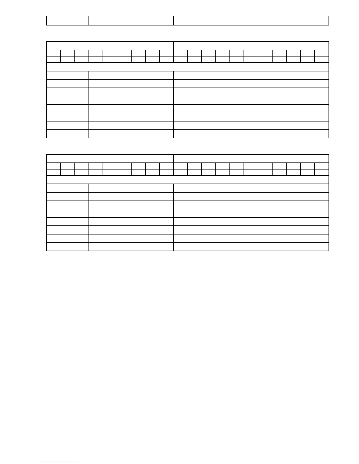
18-20 CCC Zone No or user’s No
SURGARD MRL2-DG SIA Protocol 1
1 2 3 4 5 7 8 9 10 11 12 13 14 15 1 17 18 19 20
3 r r l s s s s a a a a a a X X C C C C
# Title Explanation
1 Protocol No 3
2-3 Receiver’s No Possible No 1 to 99
4 Line number Line number
5-8 Space 4 spaces
9-14 Object No Object No symbols
15-1 XX SIA event code
17-20 CCCC Zone number
SURGARD MRL2-DG Ademco Express 4+2
1 2 3 4 5 7 8 9 10 11 12 13 14 15 1 17 18 19 20
1 r r l s s s s a a a a a a s s s s C C
#Title Explanation
1 Protocol No 1
2-3 Receiver’s No Possible No 1 to 99
4 Line number Line number
5-8 Space 11 spaces
9-14 Object No Object No symbols
15-18 Space 4 spaces
19-20 CC Zone No or user’s No
TRIKDIS
Draugystės g. 17, LT-51229 Kaunas, Lietuva, tel. 8-37-408040, faks. 8-37-7 0554
14

Annex B
Layout of contacts of external power supply connector
Contact Description
1 Negative terminal “0 V”
2 Positive terminal “+12 V”
3 Free
4 Grounding terminal
TRIKDIS
Draugystės g. 17, LT-51229 Kaunas, Lietuva, tel. 8-37-408040, faks. 8-37-7 0554
15

TRIKDIS
Draugystės g. 17, LT-51229 Kaunas, Lietuva, tel. 8-37-408040, faks. 8-37-7 0554
16

TRIKDIS
Draugystės g. 17, LT-51229 Kaunas, Lietuva, tel. 8-37-408040, faks. 8-37-7 0554
17
ANNEX C
ervice messages
Message Code Description
Service messages of the router
RECEIVER RESET D0 Router overloaded
HW CONNECTED C1 Device connected
HW DISCONNECTED C0 Device disconnected
COM ERROR 05 Communication troubles with the router
COM RESTORE 0 Communication with the router restored
Service messages of GSM reception modules RG1, RG2 and RG3
RECEIVER RESET E0 The module overloaded
GSM REGISTERED B0 Modem has registered in GSM network
GSM UNREGISTERED B1 Modem failed to register in GSM network
GPRS CONNECTED B2 GPRS server connected (RG3 only)
GPRS DISCONNECTED B3 GPRS server disconnected (RG3 only)
GSM LOW LEVEL C4 Insufficient GSM level
(correspond to one bar on the monitor of a
mobile phone);
Service messages of the telephonic reception module R 2
RECEIVER RESET E0 The module is overloaded
TEL LINE ERROR 20 Telephone line failure or disconnection
TEL LINE OK 30 Telephone line restored
Service messages of the radio reception modules RF7, RF7U
RECEIVER RESET E0 The module overloaded
HIGH NOISE C2 Broadcasting background noise more than
permissible.
NORMAL NOISE C3 Broadcasting background noise reduced up
to the limit of sensibility.

TRIKDIS
Draugystės g. 17, LT-51229 Kaunas, Lietuva, tel. 8-37-408040, faks. 8-37-7 0554
18

TRIKDIS
Draugystės g. 17, LT-51229 Kaunas, Lietuva, tel. 8-37-408040, faks. 8-37-7 0554
19
Table of contents
Other Trikdis Receiver manuals


