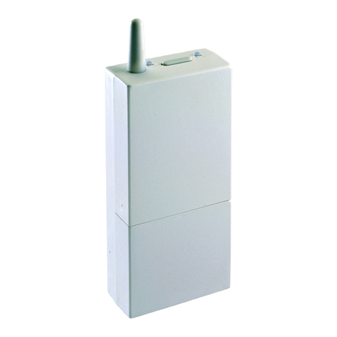
Elesta RZM610A010 User manual

164590/06.10
Ricevitore radio
RZM610A010
Istruzioni di montaggio
1 Messa in funzione
Aprire il coperchietto dell’apparecchio e collegare i due poli
della morsettiera alla porta RFB di ECONESTA o alla
porta D-Bus di un regolatore RDO.
Alla messa sotto tensione del regolatore si accenderà in
modo continuo il LED verde del ricevitore indicante il
funzionamento corretto.
Il LED rosso interno, vicino alla morsettiera, può assumere
tre aspetti diversi:
- Acceso: Al regolatore non risultano sonde istallate
- Spento: Al regolatore risulta istallata almeno una sonda
- Lampeggiante: Al regolatore ECONESTA risulta un
errore
2 Associazione di una sonda
Al ricevitore possono essere associate una sonda esterna
e fino a 7 sonde d’ambiente attribuibili a 7 zone. La sonda
esterna deve sempre essere attribuita alla zona 0.
Récepteur radio
RZM610A010
Instructions de montage
1 Montage
Le récepteur radio est à brancher au D-Bus du régulateur.
Les connexions se situent sous le couvercle de l’appareil.
À la mise sous tension du régulateur la LED verte du
récepteur s’allume, indiquant le fonctionnement correct.
La LED rouge interne, près des bornes, affiche les états
suivants:
- Allumée: Aucun appareil radio n’est annoncé au
régulateur
- Éteinte: Au moins un appareil radio est annoncé au
régulateur
- Clignotant: Le régulateur signal une erreur
2 Association des appareils radio
On peut associer au récepteur radio une sonde extérieure
radio et jusqu’à 7 commandes à distance radio (7 zones).
La sonde extérieure est attribuée à la zone 0.
Funkempfänger
RZM610A010
Montageanleitung
1 Montage
Der Funkempfänger wird am D-Bus des Reglers
angeschlossen. Die Anschlüsse befinden sich unter
dem Deckel an der Unterseite des Funkempfängers.
Die grüne LED am Funkempfänger zeigt die korrekte
Funktionsweise an.
Mit der internen, roten LED neben den Klemmen
werden folgende Zustände angezeigt:
- Dauernd EIN: Kein Funkgerät am Regler angemeldet
- Dauernd AUS: Mindestens ein Funkgerät am Regler
angemeldet
- Blinkt: Fehlermeldung vom Regler
2 Zuordnung der Funkgeräte
Dem Funkempfänger können ein Funkaussenfühler und
bis zu 7 Funkfernbedienungen (7 Zonen) zugeordnet
werden. Der Funkaussenfühler muss der Zone 0
zugewiesen werden.
Wireless receiver
RZM610A010
Installation instructions
1 Mounting
The wireless receiver is connected to the D-bus of the
controller. The connectors are located under the cover
at the bottom of the wireless receiver.
The green LED on the receiver indicates the correct
functioning.
The internal red LED next to the terminals shows the
following states
- Continuously ON: No wireless device registered at the
controller
- Continuously OFF: At least one wireless device is
registered at the controller
- Flashing: Error message from controller
2 Assignment of wireless devices
One wireless output sensor and up to seven wireless
remote controls (7 zones are assigned) can be assigned
to the receiver. The output sensor must be assigned to
zone 0.

164590/06.10
3 Vorgehensweise bei der Zuordnung
- Um den Zuordnungsmodus zu starten, Taste des
Funkempfängers drücken bis die rote LED blinkt (1
kurzer Puls), die grüne LED erlischt.
- Der Funkempfänger ist nun bereit ein Gerät der Zone
0 (Funkaussenfühler) zuzuordnen. Das Vorgehen für
die Zuordnung des Funkaussenfühlers ist in der
entsprechenden Montageanleitung (164591)
beschrieben. Nach korrekter Zuordnung leuchtet die
grüne LED, die rote LED blinkt weiter.
- Um das nächste Funkgerät zu wählen, Taste des
Funkempfängers erneut kurz drücken. Die rote LED
blinkt weiter, 2 kurze Pulse zeigen an, dass die
Funkfernbedienung für Zone 1 eingerichtet werden
kann. Stimmt die Anzahl kurzer Pulse nicht oder
leuchtet die grüne LED, muss die Taste des
Funkempfängers erneut kurz gedrückt werden. Das
Vorgehen für die Zuordnung der
Funkfernbedienungen ist in der entsprechenden
Montageanleitung (164586) beschrieben. Nach
korrekter Zuordnung leuchtet die grüne LED, die rote
LED blinkt weiter.
- Der Vorgang ist für jede Funkfernbedienung zu
wiederholen.
- Nachdem alle Geräte zugeordnet sind, wird der
Zuordnungsmodus beendet indem die Taste am
Funkempfänger 3s lang gedrückt wird. Die rote LED
erlischt, die grüne LED leuchtet.
VORSICHT
- Pro Zone nur ein Gerät zuordnen. Doppelte
Zuordnungen verursachen Störungen im Betrieb.
- Die Anzahl Pulse der roten LED am Funkempfänger
entsprechen nicht der Zonennummer. Die Angabe ist
immer um eine Zone verschoben (1 Puls für Zone 0, 2
Pulse für Zone 1, usw.).
HINWEISE
- Alle Zuordnungen werden gelöscht, indem die Taste
am Funkempfänger so lange gedrückt wird (ca. 10s)
bis die beiden LED schnell blinken.
3 Associazione dei componenti
- Per attivare la modalità di associazione premere il tasto
finché la LED rossa lampeggia (1 impulso corto) e la
LED verde si spegne.
- Il ricevitore è pronto per ricevere il segnale
d’associazione per la zona 0 (sonda esterna). La
procedura d’associazione della sonda esterna è
descritta nell’istruzione di montaggio corrispondente
(164591). Ad associazione avvenuta la LED verde si
accende, la LED rossa continua a lampeggiare.
- Per selezionare il prossimo apparecchio, premere il
tasto sul ricevitore. La LED rossa continua a
lampeggiare. 2 lampeggi segnalano la disponibilità di
ricezione del comando ambiente in zona 1. Se il numero
di lampeggi è errato o la LED verde è accesa, è
necessario premere ancora una volta il tasto. La
procedura d’associazione del comando ambiente è
descritta nell’istruzione di montaggio corrispondente
(164586). Ad associazione avvenuta la LED verde si
accende, la LED rossa continua a lampeggiare.
- La procedura va ripetuta per ogni comando ambiente.
- Dopo aver associato tutti gli apparecchi desiderati, si
esce dalla modalità di associazione premendo per 3s il
tasto del ricevitore. La LED rossa si spegne, la LED
verde è accesa.
ATTENZIONE
- Associare solo un apparecchio per zona. Associazioni
doppie provocano malfunzionamenti del sistema
- Il numero di pulsi della LED rossa sul ricevitore non
corrisponde al numero di zona. La quantità di pulsi è
sempre spostata di un numero (1 pulso per zona 0, 2
pulsi per zona 1, ecc).
INDICAZIONI
- Tutte le associazioni saranno cancellate se il tasto del
ricevitore resta premuto per circa 10s, i due LED
lampeggiano rapidamente.
3 Mise en service
- Pour démarrer le mode d’association, appuyer sur la
touche jusqu’à ce que la LED rouge clignote (1
clignotement), la LED verte s’éteint.
- Le récepteur est prêt à recevoir le signal d’association
de la zone 0 (sonde extérieure radio). Le procédé
d’association de la sonde extérieure radio est décrit
dans l’instruction de montage correspondante (164591).
Une fois le signal reçu la LED verte s’allume, la LED
rouge continue à clignoter.
- Pour sélectionner le prochain appareil radio, appuyer
brièvement la touche. La LED rouge continue à
clignoter, 2 clignotements indiquant que le récepteur est
prêt à recevoir le signal d’association de la zone 1. Si le
nombre de clignotements est faux ou si la LED verte est
allumée, appuyer à nouveau brièvement la touche. Le
procédé d’association de la commande à distance radio
est décrite dans l’instruction de montage correspondante
(164586). Une fois le signal reçu la LED verte s’allume,
la LED rouge continue à clignoter.
- Le processus est à répéter pour chaque commande à
distance radio.
- S’il n’y a pas d’autres appareils à associer, appuyer sur
la touche pendant 3s pour quitter le mode d’association.
La LED rouge s’éteint, la LED verte est allumée.
ATTENTION
- Seul un appareil radio peut être associé par zone. La
double attribution d’un appareil radio à la même zone
cause un dysfonctionnement du système.
- Le nombre de clignotement ne correspond pas au
numéro de la zone. Il est décalé d‘une impulsion (1
impulsion pour zone 0, 2 impulsions pour zone 1, etc.).
REMARQUES
- On peut annuler toute les associations en appuyant sur
la touche (env. 10s) jusqu’à ce que les deux LED
clignotent rapidement.
3 Assignment procedure
- To start the association mode, press the button of the
wireless receiver until the red LED flashes (1 short
pulse) and the green LED switches off.
- The receiver is now ready for the assignment of a
device for zone 0 (wireless outdoor sensor). The
assignment procedure for the outdoor sensor is
described in the corresponding instructions (164591).
After correct assignment, the green LED is ON, the
red LED keeps flashing.
- To assign the next wireless device, press the button
of the receiver again briefly. The red LED continues
flashing, two short pulses indicate that the remote
control for zone 1 can be assigned. If the number of
short pulses is wrong, or the green LED is active, the
button of the radio receiver must be pressed again.
The assignment procedure for the wireless remote
controls is described in the corresponding instructions
(164586). After correct assignment, the green LED is
ON, the red LED keeps flashing.
- This process has to be repeated for each remote
control to be installed.
- After all devices are assigned, the assignment mode
is finished by pressing the button on the receiver for 3
seconds. The red LED goes out, the green LED is lit.
CAUTION
- Assign only one device to each zone. Double
assignments cause disturbances in operation.
- The number of pulses of the red LED on the receiver
does not correspond to the zone number. This
information is always one zone shifted (one pulse for
zone 0, two pulses for zone 1, etc.).
NOTES
- All assignments are deleted by long pressing the
button on the receiver (about 10s). The two LEDs will
flash quickly.
Table of contents
Popular Receiver manuals by other brands
Jensen
Jensen DUAL CMR2629 Installation & owner's manual
Cobalt Digital Inc
Cobalt Digital Inc BlueBox BBG-OE-MK2 Fiber-To-Coax quick start guide
Elan
Elan EL-4KHDBT-RX-40-18G Quick reference guide
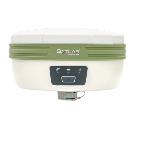
SatLab
SatLab SL700 GNSS RTK Getting started

SHENZHEN FLYING INDUSTRY DEVELOPMENT
SHENZHEN FLYING INDUSTRY DEVELOPMENT S1PUW-AC-ANT3 manual

American Fibertek
American Fibertek RRM-30 Instruction manaul
