Termaline® Load Resistor
viii
About This Manual
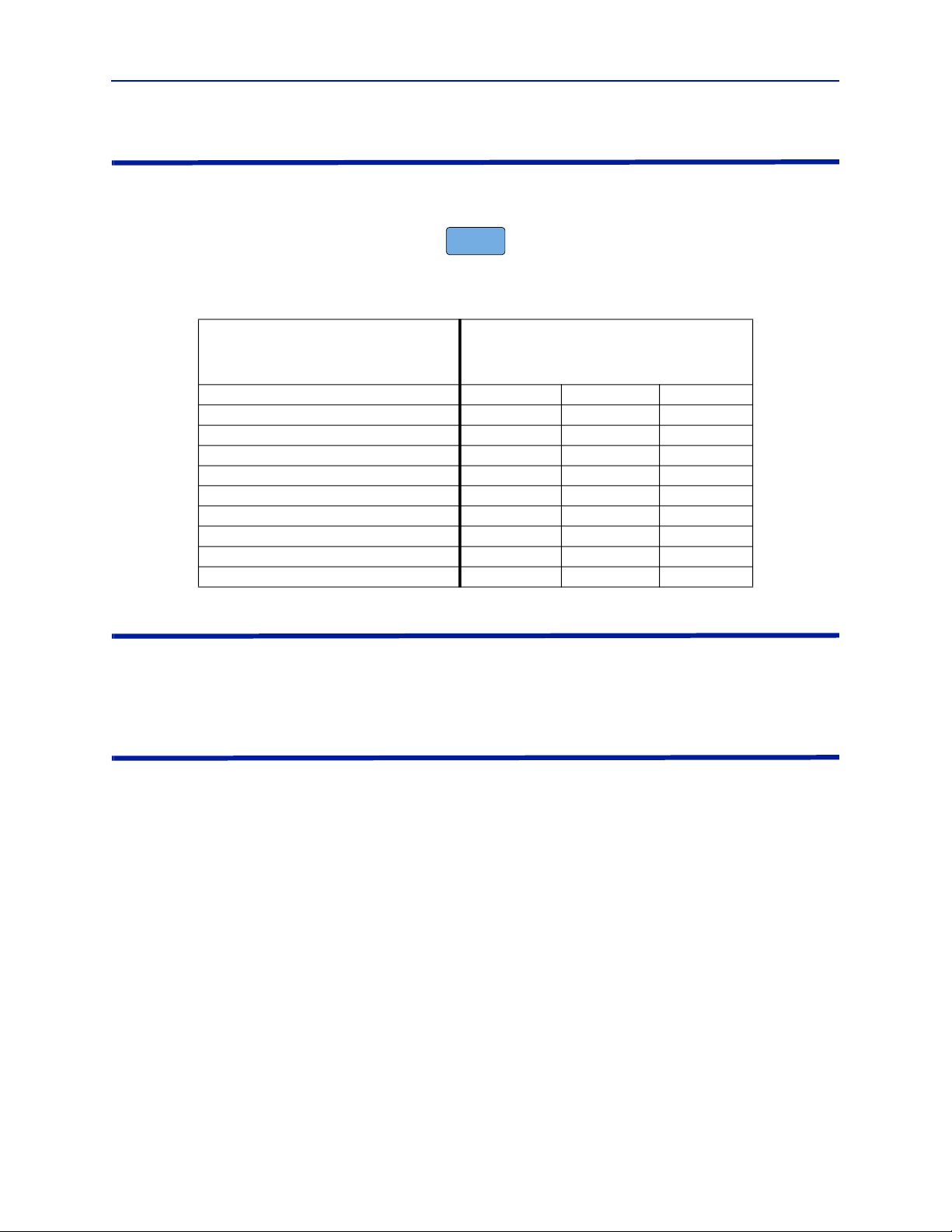
This manual covers the operating and maintenance instructions for the following models
When used in the rest of the manual, 8890 series refers to all models. 889x–300 refers only to
loads without a blower. –315 and –320 refer to loads with attached blowers.
Changes to this Manual
We have made every effort to ensure this manual is accurate. If you discover any errors, or if you have suggestions
for improving this manual, please send your comments to our Solon, Ohio factory. This manual may be periodically
updated. When inquiring about updates to this manual refer to the part number and revision on the title page.
Chapter Layout
Introduction — Describes the features of the Bird Termaline, Semiconductor, RF Load Resistor lists equipment
supplied and optional equipment, and provides power-up instructions.
Theory of Operation — Describes how the Termaline, Semiconductor, RF Load Resistor works and its functions.
Installation — Describes the how to install the Termaline, Semiconductor, RF Load Resistor.
Operation with Blower — Describes procedures require for operating the load resistor equipped with a blower
unit.
Maintenance — Lists routine maintenance tasks as well as troubleshooting for common problems. Specifications
and parts information are also included.
Connector
Model Number
Without
Blower
Blower,
115 VAC
Blower,
230 VAC
Female LC 8890-300 8890-315 8890-320
3-1/8" EIA Flanged 8891-300 8891-315 8891-320
1-5/8" EIA Flanged 8892-300 8892-315 8892-320
1-5/8" EIA Unflanged 8895-300 8895-315 8895-320
3-1/8" Unflanged, Flush Center, 51.58896-300
3-1/8" Unflanged, Flush Center 8897-300 8897-315 8897-320
3-1/8" Unflanged, Recessed Center 8898-300 8898-315 8898-320
Digital, 3-1/8" EIA Flanged 8891D300
Digital, 1-5/8" EIA Flanged 8892D300 8892D320
Digital, Female 13-30 8892D13-30