manuals.online logo
Brands
  1. Home
  2. •
  3. Brands
  4. •
  5. M-system
  6. •
  7. Surge Protector
  8. •
  9. M-system MGD-24 User manual

M-system MGD-24 User manual

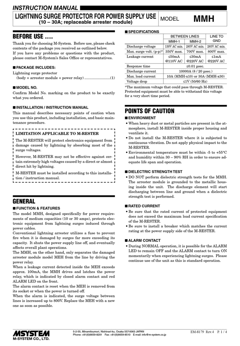
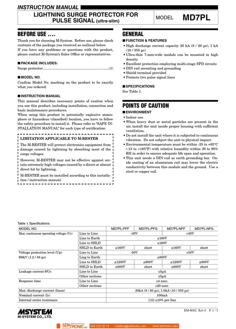
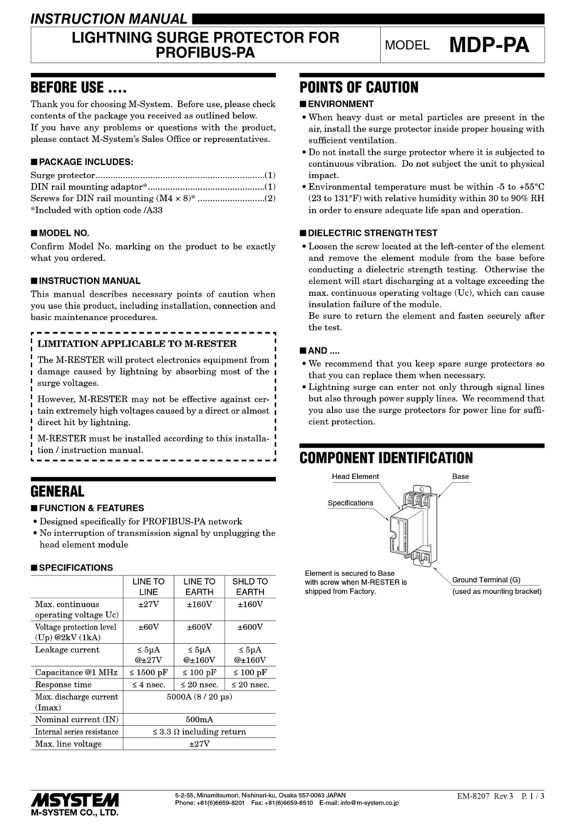
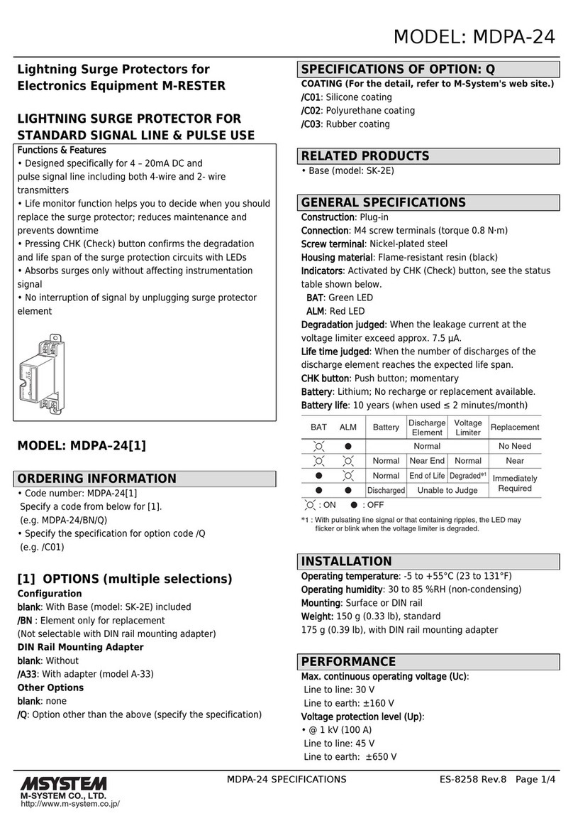
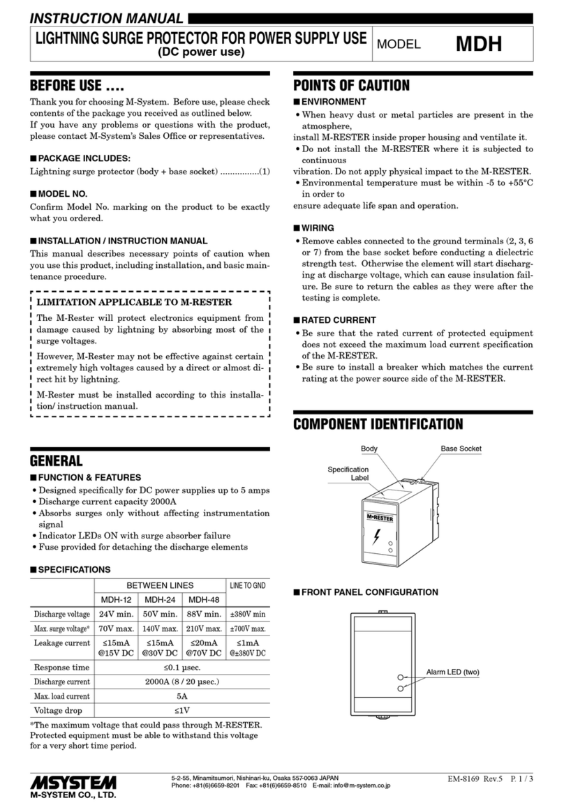
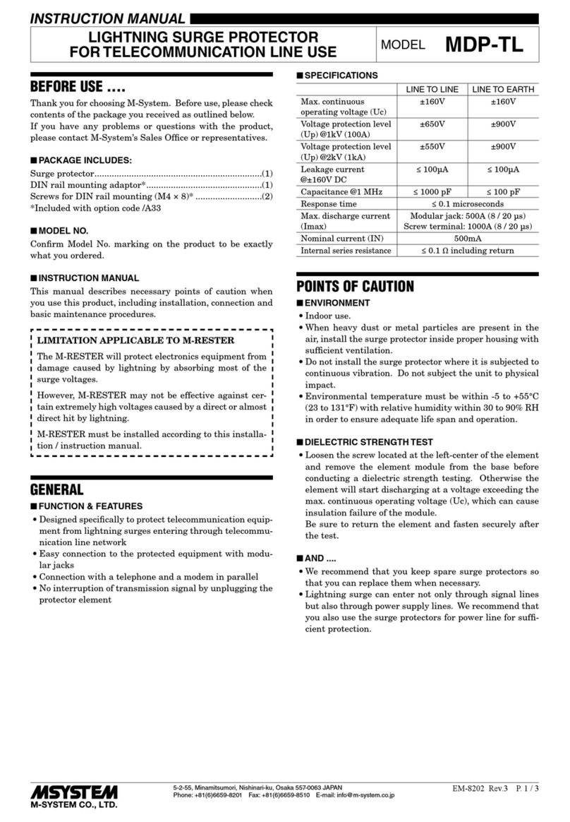
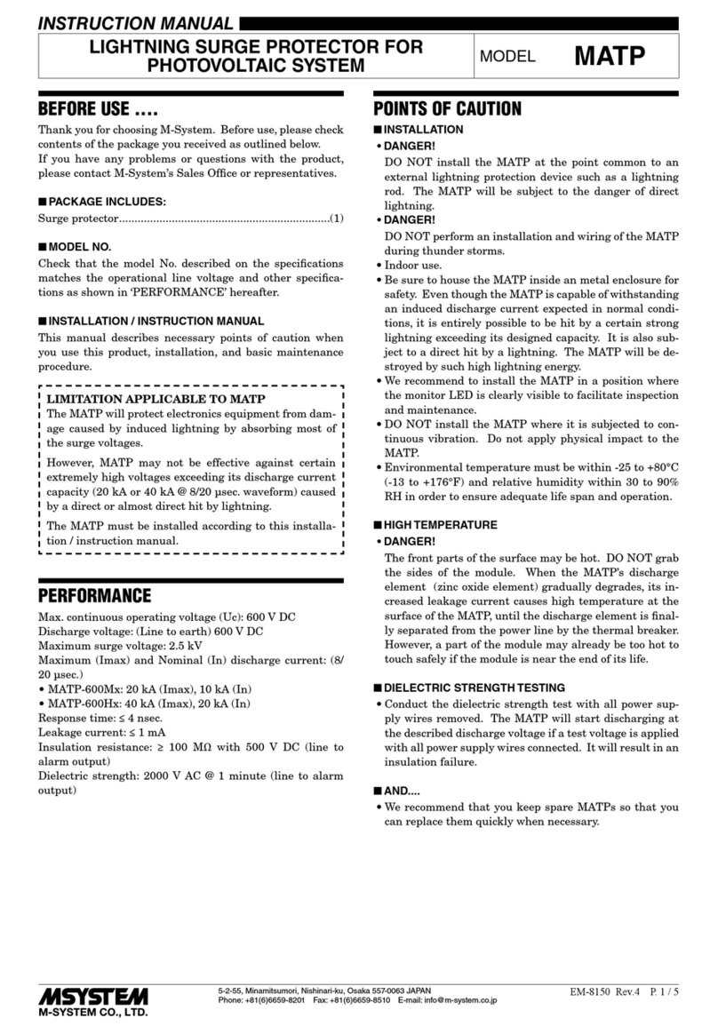
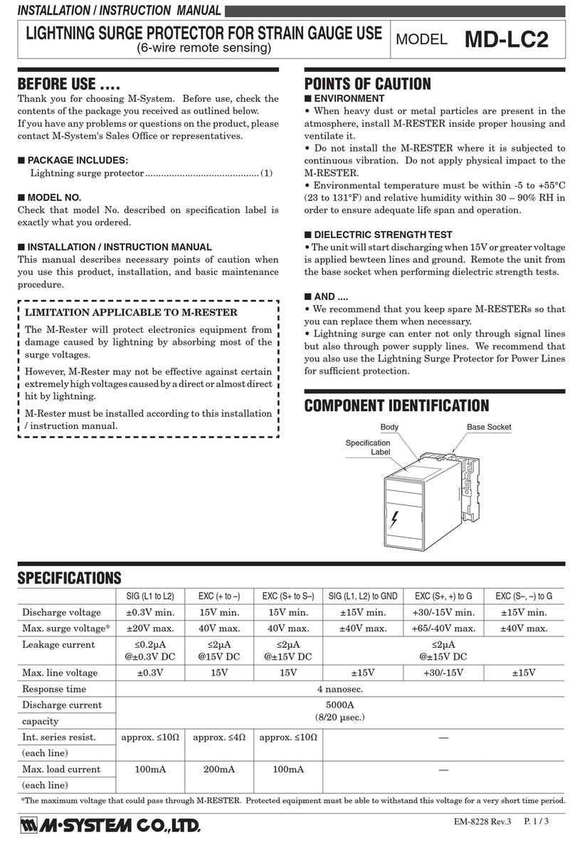
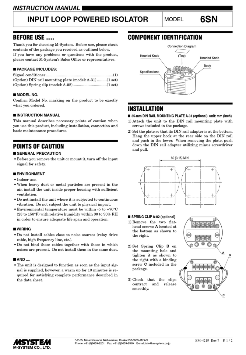
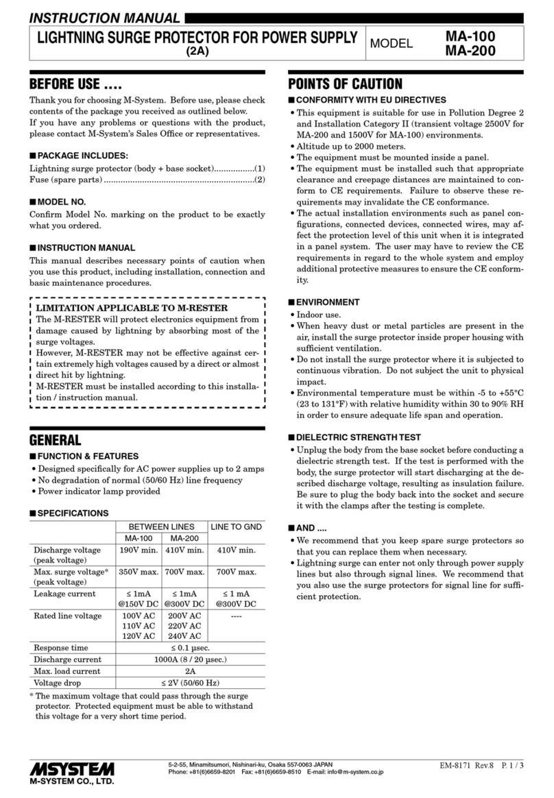
BEFORE USE ....
Thank you for choosing M-System. Before use, please check
contents of the package you received as outlined below.
If you have any problems or questions with the product,
please contact M-System’s Sales Office or representatives.
■PACKAGE INCLUDES:
Lightning surge protector...................................................(1)
■MODEL NO.
Confirm Model No. marking on the product to be exactly
what you ordered.
■INSTALLATION / INSTRUCTION MANUAL
This manual describes necessary points of caution when
you use this product, including installation, and basic main-
tenance procedure.
LIMITATION APPLICABLE TO M-RESTER
The M-RESTER will protect electronics equipment from
damage caused by lightning by absorbing most of the
surge voltages.
However, M-RESTER may not be effective against cer-
tain extremely high voltages caused by a direct or almost
direct hit by lightning.
M-RESTER must be installed according to this installa-
tion / instruction manual.
GENERAL
■FUNCTION & FEATURES
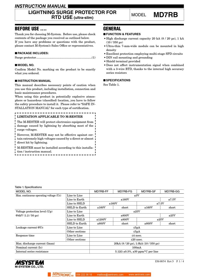
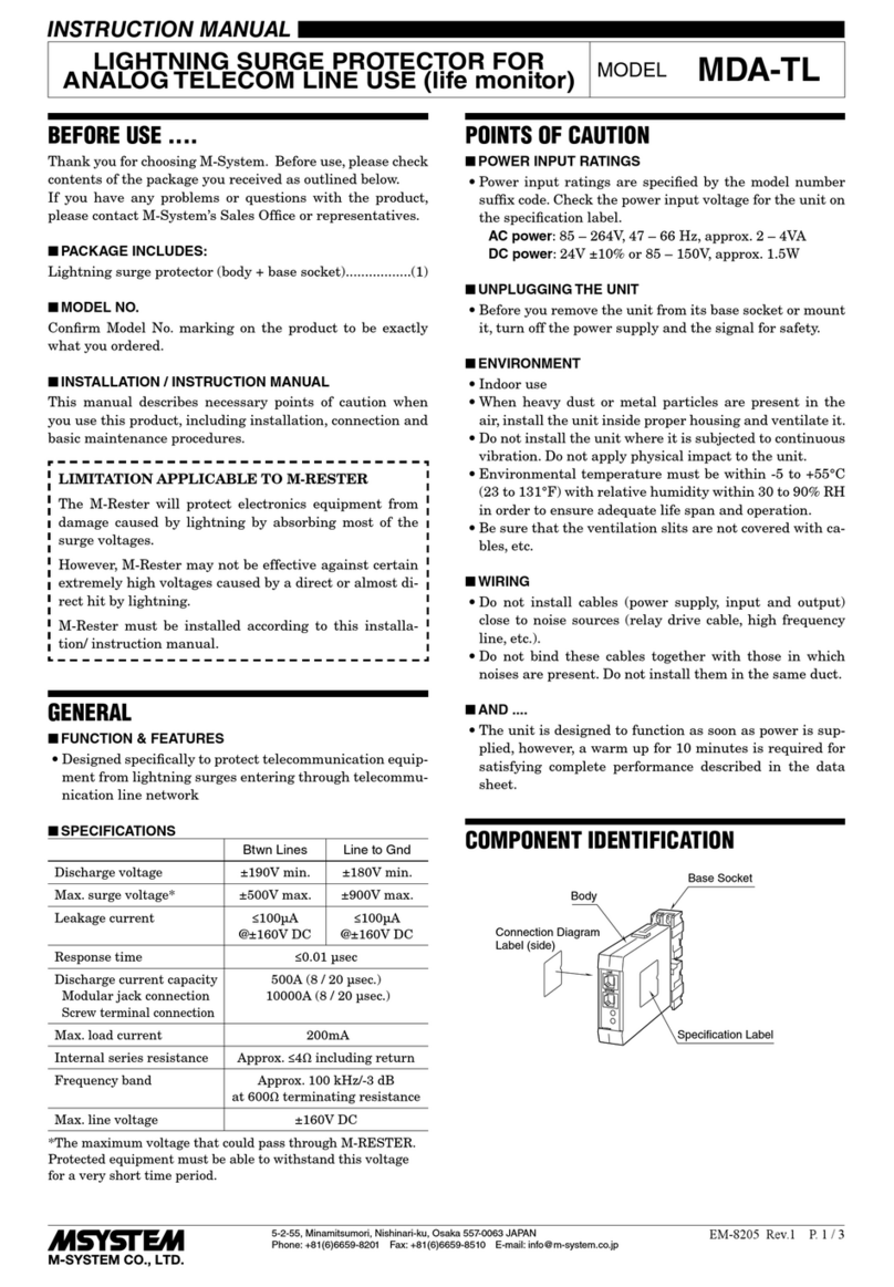
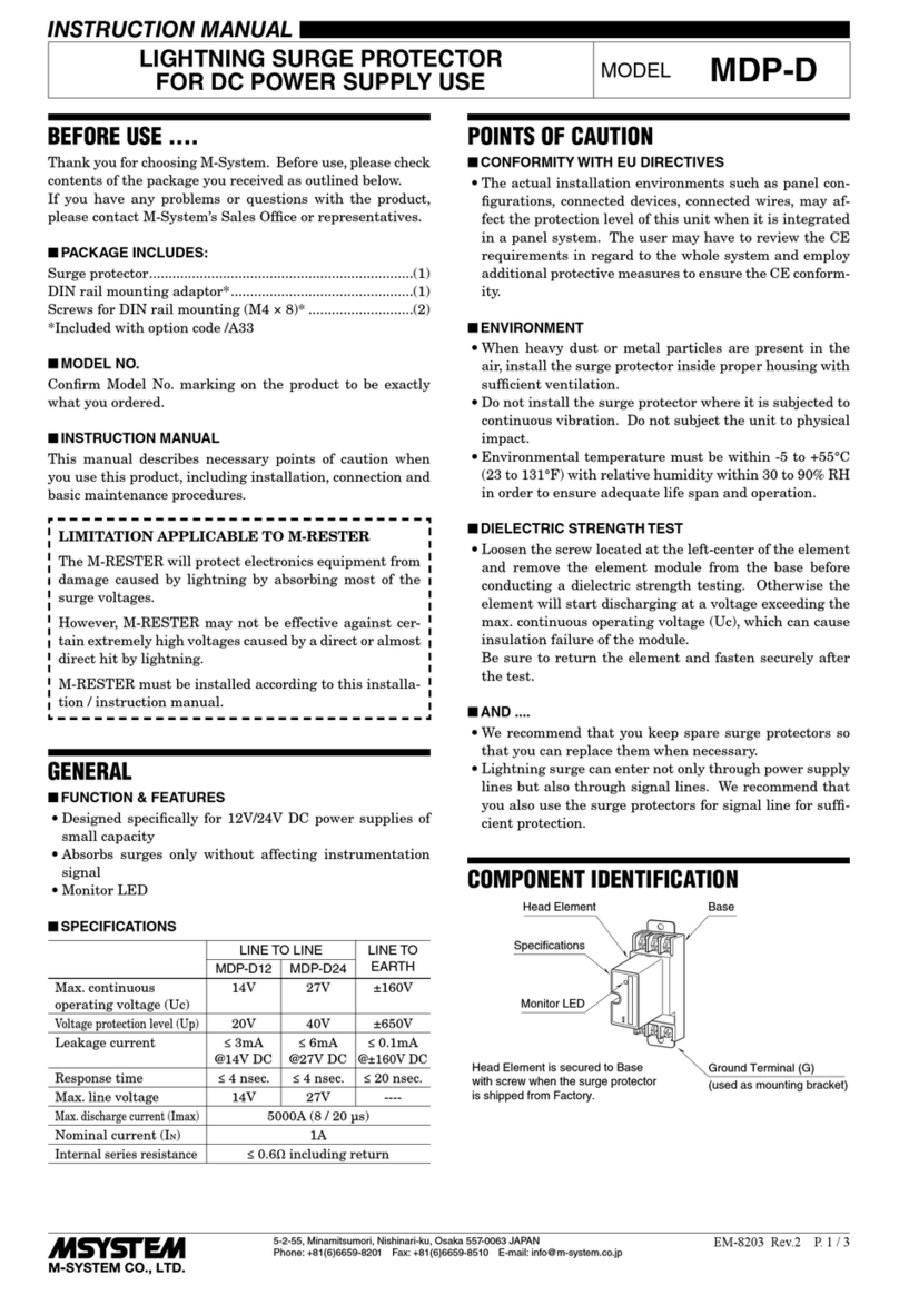
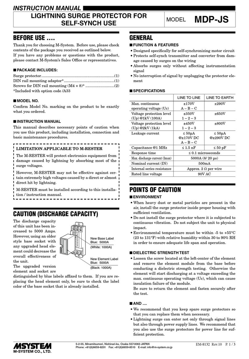
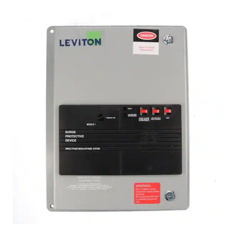
• Specifically designed to protect 4 to 20mA DC signal line
including both 4-wire and 2-wire transmitters from dam-
age caused by lightning surges
• Absorbs surges only without affecting transmitted sig-
nals.
■SPECIFICATIONS
BETWEEN LINES LINE TO
GND
MGD-24 MGD-65
Discharge voltage 30V min. 70V min.
±500V max.
Max. surge voltage* 40V max. 80V max.
±650V max.
Leakage current ≤5μA
@30V DC
≤5μA
@70V DC
≤5μA
@±140V DC
Max. line voltage 30V DC 70V DC –––
Response time ≤0.1 μsec.
Discharge current 1000A (8 / 20 μsec.)
Max. load current 100mA
Internal series resist. approx. 20Ω including return
POINTS OF CAUTION
■ENVIRONMENT
• When heavy dust or metal particles are present in the at-
mosphere, install M-RESTER inside proper housing and
ventilate it.
• Do not install the M-RESTER where it is subjected to
continuous vibration. Do not apply physical impact to the
M-RESTER.
• Environmental temperature must be within -5 to +55°C
(23 to 131°F) and relative humidity within 30 to 90% RH
in order to ensure adequate life span and operation.
■DIELECTRIC STRENGTH TEST
• DO NOT perform dielectric strength tests with wires con-
nected to the unit. Otherwise the element will start dis-
charging at discharge voltage, which can cause insulation
failure. Be sure to return the wires after the test.
■AND ....
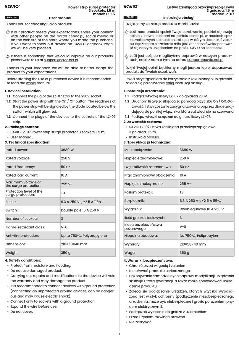
• We recommend that you keep spare M-RESTERs so that
you can replace them when necessary.
• Lightning surge can enter not only through signal lines
but also through power supply lines. We recommend that
you also use the Lightning Arrester for Power Lines for
sufficient protection.
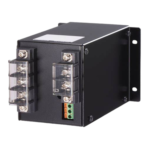
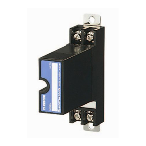
COMPONENT IDENTIFICATION
Body
Terminal Cover
Specification Label
LIGHTNING SURGE PROTECTOR FOR
STANDARD SIGNAL LINE & PULSE USE
MODEL
MGD-24/MGD-65
5-2-55, Minamitsumori, Nishinari-ku, Osaka 557-0063 JAPAN
Phone: +81(6)6659-8201 Fax: +81(6)6659-8510 E-mail: info@m-system.co.jp
EM-8211 Rev.4 P. 1 / 4
INSTRUCTION MANUAL
INSTALLATION
Refer to the following drawings.
■EXERNAL DIMENTIONS unit: mm [inch]
102 [4.02]
3 [.12]
51 [2.01]
80 [3.15]
TERMINAL COVER
2–4.3 [.17] dia.
MTG HOLE
7–M3.5 SCREW
8 [.31]
91 [3.58]
99 [3.90 ]
25 [.98]
12
3
56
78
• When mounting, no extra space is needed between units.
■MOUNTING REQUIREMENTS mm (inch)
91 (3.58)
83 (2.27)
26 (1.02)
ANGLE BRACKET
2–M3.5 SCREW
MGD-24 / MGD-65
5-2-55, Minamitsumori, Nishinari-ku, Osaka 557-0063 JAPAN
Phone: +81(6)6659-8201 Fax: +81(6)6659-8510 E-mail: info@m-system.co.jp
EM-8211 Rev.4 P. 2 / 4
TERMINAL CONNECTIONS
Connect the unit as in the diagram below.
Be sure to cross-wire between the Ground terminal (3) and metallic housing of the protected equipment. (100W max.)
MDP-24-1
MDP-65-1
IN
RACK-MOUNTED
SURGE PROTECTOR
CURRENT LOOP SUPPLY
CENTRAL
STATION
FIELD
(PROTECTED EQUIPMENT)
G
S
S
FROM
FIELD
TO
CENTRAL
STATION
+
–3
5
7
1
P–
P+
S–
S+
CABLE
G
G
Connection example with Ch.1 of MGD-24/65
and model MDP-24-1/65-1.
■GROUNDING
M-RESTER PROTECTED
EQUIPMENT
G
G
CROSSOVER WIRE
GROUNDING
(100 ohms or less)
A crossover wire between M-RESTER ground and ground or metallic
housing of equipment is required for protection.
If the protected equipment has no ground terminal, ground the
M-RESTER only.
MGD-24 / MGD-65
5-2-55, Minamitsumori, Nishinari-ku, Osaka 557-0063 JAPAN
Phone: +81(6)6659-8201 Fax: +81(6)6659-8510 E-mail: info@m-system.co.jp
EM-8211 Rev.4 P. 3 / 4
MAINTENANCE
Check M-RESTER periodically. Many cases of lightning are
ignored, and even lightning at a far distance often causes
inductive surges. We recommend that you check your M-
RESTER about twice a year, before and after the rainy
season. Check whenever you experience a strong lightning
occurrence.
Checking procedure is explained in the following:
■CHECKING
WIRING
• Make sure that wiring is done as instructed in the con-
nection diagram.
• Make sure that the Ground terminal (3) is connected to
the metallic housing of protected equipment.
• Make sure that the Ground terminal (3) is grounded to
earth.
DISCHARGE FUNCTION
Remove all the wires connected to the M-RESTER and test
its discharge capability as follows:
• Apply 30V DC (MGD-24) or 70V DC (MGD-65) across
the following terminals with a resistor of approx. 50kW
in serial. Measure leakage current. (≤5mA standard)
Then apply 40V DC (MGD-24) or 80V DC (MGD-65) and
check that the discharging occurs. (≥100mA standard)
If a DC source is not available, check resistance across
these terminals on the high resistance range of multime-
ter, measured with positive potential at the terminal No.1
and 2 (infinite standard).
Terminals (1+) – (7–), (2+) – (8–)
• Apply 140V DC across the following terminals with a re-
sistor of approx. 1MW in serial. Measure leakage current.
(≤5mA standard)
Terminals (1) – (3), (2) – (3), (7) – (3), (8) – (3)
If a DC source is not available, check resistance across
these terminals on the high resistance range of multim-
eter (infinite standard).
• Check that discharging occurs across the same terminals
with a 500V DC megger. (Indicator of the megger reaches
over-scale.) Check also in the inverted polarity.
• If any of the above tests shows negative, replace the whole
MRESTER unit.
MGD-24 / MGD-65
5-2-55, Minamitsumori, Nishinari-ku, Osaka 557-0063 JAPAN
Phone: +81(6)6659-8201 Fax: +81(6)6659-8510 E-mail: info@m-system.co.jp
EM-8211 Rev.4 P. 4 / 4

This manual suits for next models

1

Other M-system Surge Protector manuals

M-system MDP-D Series User manual

M-system

M-system MDP-D Series User manual

M-system MD7PM User manual

M-system

M-system MD7PM User manual

M-system MDP-TL User manual

M-system

M-system MDP-TL User manual

M-system MD6 24 Series User manual

M-system

M-system MD6 24 Series User manual

M-system MDP-LWA User manual

M-system

M-system MDP-LWA User manual

M-system MD7RB-FF User manual

M-system

M-system MD7RB-FF User manual

M-system MDP-LWA User manual

M-system

M-system MDP-LWA User manual

M-system MDP-65T User manual

M-system

M-system MDP-65T User manual

M-system MDP-100 User manual

M-system

M-system MDP-100 User manual

M-system MD7PA User manual

M-system

M-system MD7PA User manual

M-system MDA-TL User manual

M-system

M-system MDA-TL User manual

M-system MDP-200T User manual

M-system

M-system MDP-200T User manual

M-system MATP User manual

M-system

M-system MATP User manual

M-system MDP-PM User manual

M-system

M-system MDP-PM User manual

M-system MMAJ User manual

M-system

M-system MMAJ User manual

M-system MDK-LC User manual

M-system

M-system MDK-LC User manual

M-system MDCAT-SPE User manual

M-system

M-system MDCAT-SPE User manual

M-system MDP-PA User manual

M-system

M-system MDP-PA User manual

M-system MGA-100 User manual

M-system

M-system MGA-100 User manual

M-system MAKN User manual

M-system

M-system MAKN User manual

M-system MA-100 User manual

M-system

M-system MA-100 User manual

M-system MDCAT-A Series User manual

M-system

M-system MDCAT-A Series User manual

M-system MD7LC User manual

M-system

M-system MD7LC User manual

M-system MDP-JS User manual

M-system

M-system MDP-JS User manual

Popular Surge Protector manuals by other brands

Emerson PowerSure PST Specifications

Emerson

Emerson PowerSure PST Specifications

Monster Power Monster Power PRO 3600 owner's manual

Monster Power

Monster Power Monster Power PRO 3600 owner's manual

SPC CLEVER Power Strip user guide

SPC

SPC CLEVER Power Strip user guide

Panamax M4310 instructions

Panamax

Panamax M4310 instructions

Emos P54222 manual

Emos

Emos P54222 manual

Monacor AHVB-240BNC quick start guide

Monacor

Monacor AHVB-240BNC quick start guide

PROCET PT-PR01G-10 Quick installation guide

PROCET

PROCET PT-PR01G-10 Quick installation guide

APCO Aviation P5B-FR quick start guide

APCO Aviation

APCO Aviation P5B-FR quick start guide

BLACK DECKER BDXPA0041 instruction manual

BLACK DECKER

BLACK DECKER BDXPA0041 instruction manual

Tripp Lite B110-SP-CAT quick start guide

Tripp Lite

Tripp Lite B110-SP-CAT quick start guide

Tripp Lite TLP2USBD Specification sheet

Tripp Lite

Tripp Lite TLP2USBD Specification sheet

Tripp Lite Super Series UL1449330 owner's manual

Tripp Lite

Tripp Lite Super Series UL1449330 owner's manual

Rocket Fish RF-HTS205 Quick setup guide

Rocket Fish

Rocket Fish RF-HTS205 Quick setup guide

Tripp Lite DG206 Specification sheet

Tripp Lite

Tripp Lite DG206 Specification sheet

Tripp Lite Isobar HT10DBS owner's manual

Tripp Lite

Tripp Lite Isobar HT10DBS owner's manual

Black Box SP143A-R2 Specifications

Black Box

Black Box SP143A-R2 Specifications

Tripp Lite is250hg Specification sheet

Tripp Lite

Tripp Lite is250hg Specification sheet

Tripp Lite ISOBAR12ULTRA AGIB120V12SSRM Specifications

Tripp Lite

Tripp Lite ISOBAR12ULTRA AGIB120V12SSRM Specifications

manuals.online logo
manuals.online logoBrands
  • About & Mission
  • Contact us
  • Privacy Policy
  • Terms and Conditions

Copyright 2025 Manuals.Online. All Rights Reserved.