Black cat BC 2400 User manual

Owners Manual
Bedienungsanleitung
Manuel d'utilisation
Manuale d’istruzioni
Instrukcja Obsługi
Handboek
Instrukcja obsługi
manuál
Návod na používanie
ELEKTROBOOTSMOTOREN
MOTEURS ELECTRIQUES
SILNIKI ELEKTRYCZNE
MOTORE ELETTRICO
ELEKTROMOS CSÓNAKMOTOROK
ELEKTRISCHE BUITENBOORDMOTOREN
ZÁVĚSNÉ ELEKTROMOTORY
ELEKTRICKÉ MOTORY
ELECTRIC OUTBOARD MOTOR

2
Power Propeller
Multi adjustable depth feature
Motor unit
Steering facility
Drawer compartment
for remote control
Battery cable
Quick tilt device
Corrosion-resistant shaft
Remote control with
spiral safety cord

3
Motor unit
Quick tilt device
Service and repairs may only be carried out by Zebco Europe
GmbH or service partners.
CAUTION: The warranty is valid only for use in
fresh water. The warranty is void if the motor
has been used in brackish or seawater. If the
motor is to remain attached to the boat after
use, it must always be lifted out of the water
via the pivoting mechanism.
2. SYSTEM OVERVIEW AND SETUP
2.1 Assembly
Attach the motor to the appropriate motor mount on the boat.
Make sure to tighten both mounting bolts rmly. (Fig. 1)
To adjust the mounting angle, grasp the motor head with one
hand and press in the positioning pin with the other hand. Keep
the pin pressed until the desired angle is reached. Release the
pin and make sure that the mechanism locks rmly into place
(Fig. 2)
CAUTION!When adjusting the tilt angle,
avoid placing your hands between the shaft
and the hull of the boat. RISK OF INJURY!
BLACK CAT BC2400 REMOTE ELECTRIC OUTBOARD MOTOR
OPERATING INSTRUCTIONS
1. GENERAL
Introduction ..........................................................................1.1
Warranty terms .....................................................................1.2
2. SYSTEM OVERVIEW AND SETUP
Assembly ...............................................................................2.1
Electrical connection .............................................................2.2
Switching on the motor ........................................................2.3
Remote control ......................................................................2.4
Attaching the propeller .........................................................2.5
Adjusting the depth ..............................................................2.6
Setting the steering tension...................................................2.7
3. MORE INFO
Maintenance .........................................................................3.1
Troubleshooting ....................................................................3.2
4. DECLARATION OF CONFORMITY
1. GENERAL
1.1 Introduction
Congratulations on purchasing a Black Cat electric outboard
motor.
This motor is a Zebco Europe development, specially adapted to
the requirements of shing. High-quality material and design,
in combination with sophisticated technology, make this motor
a durable and reliable companion in all situations.
The Black Cat electric outboard motor of the Battle Cat 2400
series was developed especially for belly boats. It can also be
used on light, small boats and inatable boats.
For the continuous improvement of our products, we reserve
the right to change parts and components without prior notice
or notication.To avoid unnecessary operating errors, please
read the following operating instructions carefully.
1.2Warranty terms
The Black Cat electric outboard motor is warranted for 2 years
(only valid in conjunction with proof of purchase) from the
date of purchase.The warranty does not cover wear parts such
as graphite brushes or shear pins. The warranty applies exclu-
sively to non-commercial use of the motor and does not apply
in the event of operating errors, accidents, improper repairs or
changes made to the product.
2
1

4
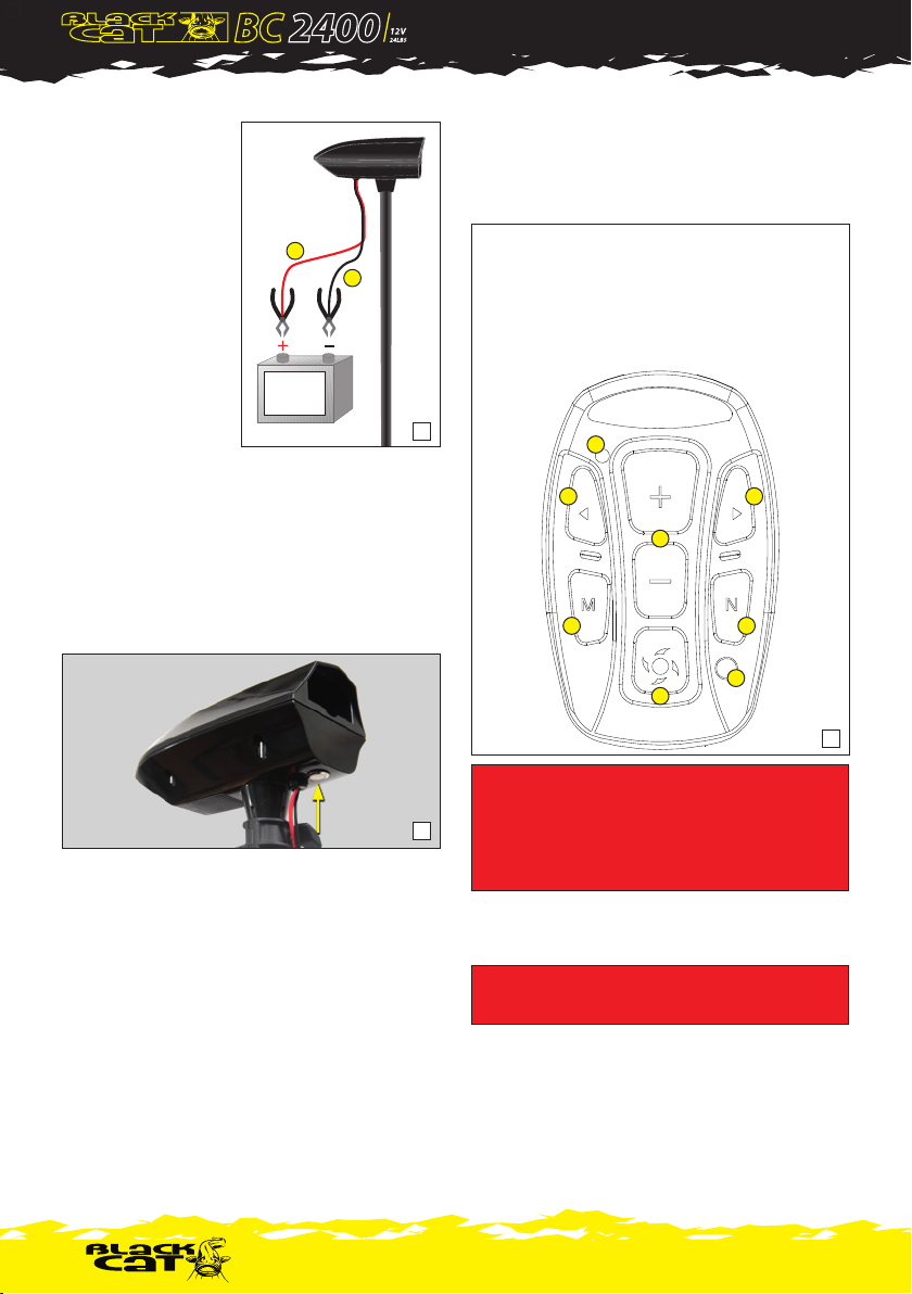
2.2 Electrical connection (for 12V battery only!)
Connect the red battery
cable (A) to the positive
terminal (marked by (+) on
the battery). Connect the
black battery cable (B) to
the negative terminal (-).
The terminals must be rmly
connected. Otherwise,
malfunctions may occur. The
battery should always be
placed in a well ventilated
place.The motor works
with all conventional 12V
batteries. Zebco Europe
recommends the use of
special marine deep dis-
charge batteries or LiFePO4 lithium batteries to ensure the best
possible operation. (Fig. 3)
2.3.Switching on the motor
The power button is located below the motor head (Fig. 4).
When the button is pressed, a short ve-tone melody sounds
and the motor is connected to the remote control
2.4 Remote control
The remote control is located in a practical clamping holder at
the top of the motor head. The remote control is synchronized
with the motor after the motor is switched on.
If this is not the case, follow these instructions:
Step 1
Connect the motor to the battery and switch it on by pressing
the power button for a maximum of two seconds.The pow-
er-on melody sounds.
Step 2
Press and hold the power button again for four seconds to put
the motor into pairing mode. This is conrmed by a short beep.
Step 3
Bring the remote control close to the motor head and press any
button (e.g. Start/Stop, button 4) on the remote control.The
remote control should now be paired with the motor.
CAUTION: If the boat is to be taken
out of the water, the motor must be
removed beforehand.
Always disconnect the battery before
attaching or removing the motor.
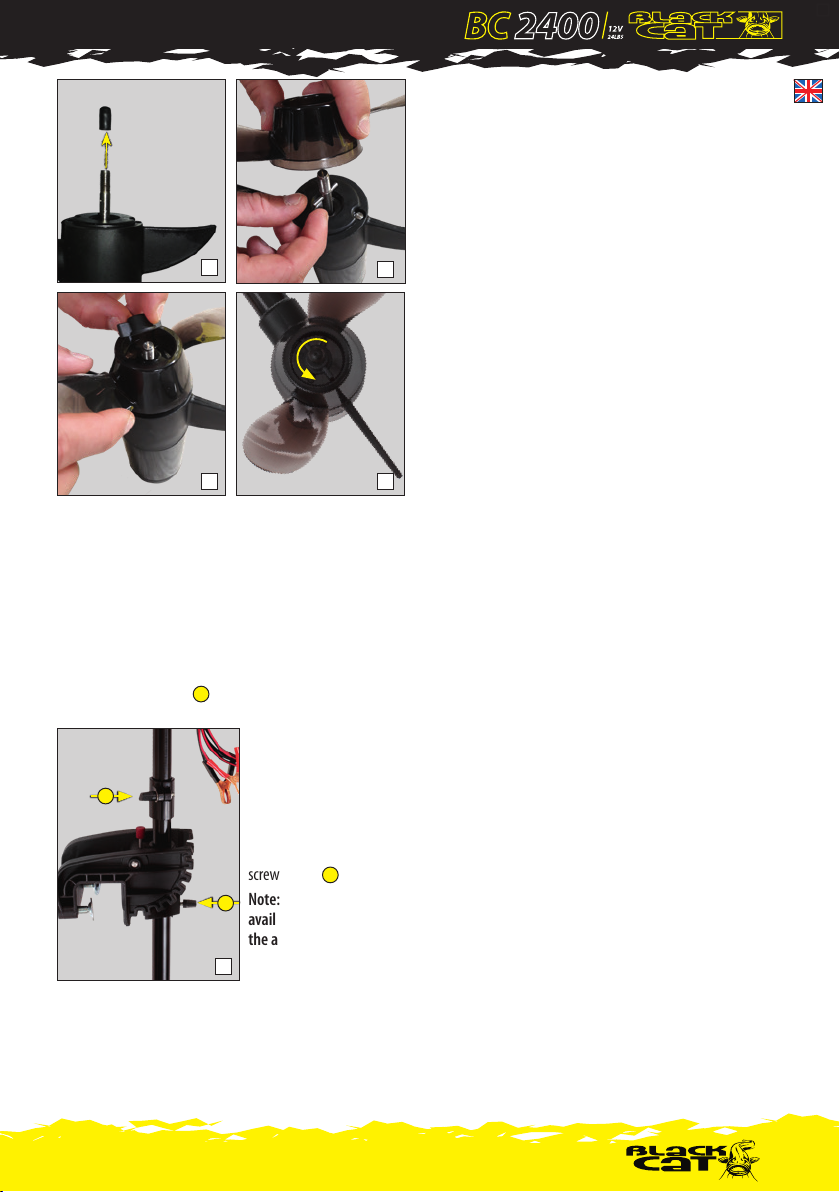
2.5 Assembling/Loosening the propeller (g. 6A-D)
CAUTION: ALWAYS disconnect the battery prior to chang-
ing the propeller.
Verify proper t of the groove and shearing pin when mounting
the new propeller, otherwise the propeller will not attach
properly.
Screw in the locknut hand-tight using the propeller wrench sup-
plied, taking care to hold the propeller with one hand to prevent
it from revolving. Do not loosen or tighten the locknut with a
Special Gel
Battery 12V
or
Li-Ion (LiFePO4)
14,8V max !
3
5
5
1
3 6
4
2
7
8
(1) no function
(2) no function
(3) maximum speed
(4) propeller On / Off
(5) + and - Increase/reduce speed
(6) no function
(7) battery test of the remote control:
LED (8) must light up briefly
4
A
B

5
hammer or similar tool, as this may cause damage to the locknut
or shaft. Once the locknut has been removed, the propeller can
be taken o easily.
After using the motor, always check for shing line or weeds that
may have got caught in the propeller and remove, if necessary.
2.6 Adjusting the depth
Hold the motor shaft with one hand, then loosen the depth
adjustment screw (Fig. 7 ) and set the motor to the desired
depth.Then re-tighten the adjusting screw rmly.
2.7 Setting the
steering tension
Steering counter tension is
achieved by loosening or
tightening the tension block
screw. (Fig. 7 ).
Note:This feature is
available only when using
the accessory tiller no.
9926128.
3. MORE INFO
3.1 Maintenance
Rinse the motor thoroughly with running water. The screws and
moving parts of the motor suspension should be lubricated with
machine oil approx. every two weeks. The electrical connections
should be checked monthly for corrosion. Replace defective
connections or cables immediately to avoid possible overheating.
After approx. 100 hours of operation, the graphite brushes of the
drive unit should be checked by Zebco Service. For longer-term
storage, make sure to keep the motor in a well-ventilated, dry
place. Do not leave the motor outdoors during the winter, as this
could cause damage to the magnet of the drive unit.
3.2Troubleshooting
Power loss
• Propeller possibly sti. Check if line or weeds are caught in the
screw. If this is the case, switch o the motor immediately to
avoid possible overheating.
• Check the charge level of the battery. Check the battery cells.
• Check the connections of the battery cable.
Power consumption too high
• Check propeller for stiness.
• Corrosion or short-circuit at cable connectors in the upper
motor housing.
• Check the battery cells.
Motor noise too loud and/or vibrations
• Check t and condition of the propeller; if necessary remount
the propeller oset by 180°.
• Bent shaft. Remove the propeller and run the motor at
medium speed, paying attention to shaft noises.
• If the shaft is bent, send the motor in for repair.
•Turn the propeller by hand, in case of stiness send in the
motor for servicing.
Motor is dicult to steer
(only when using the accessory tiller no. 9926128)
• Loosen and readjust the steering tension block screw and
apply some grease.
Remote control not functional
• Replace battery.
• Re-synchronize with motor.
For all other problems not listed here, please contact
your dealer or Zebco Service.
7
1
2
1
2
6A
6C
6B
6D

6
Power Propeller
stufenlos verstellbareTiefeneinstellung
Antriebseinheit
Steuerkopf
Einschubfach für Fernbedienung
Batteriekabel
Schnellklappvorrichtung
Korrosionsbeständiger Schaft
Fernbedienung mit
Spiral-Sicherheitsseil

7
Antriebseinheit
Schnellklappvorrichtung
unsachgemäßer Reparatur oder vorgenommenen Änderungen.
Service-Leistungen und Reparaturen dürfen ausschließlich
von der Firma Zebco-Europe GmbH oder Service Partnern
vorgenommen werden.
ACHTUNG: Die Garantie erstreckt sich nur auf den
Gebrauch im Süßwasser. Sie erlischt, wenn der Motor
im Brack- oder Meerwasser eingesetzt wurde. Wenn
der Motor nach dem Einsatz am Boot verbleibt, muss
er immer mittels der Schwenkvorrichtung aus dem
Wasser gehoben werden.
2. AUFBAU UND INBETRIEBNAHME
2.1 Montage
Befestigen Sie den Motor an der jeweiligen Motorhalterung am
Boot. Stellen Sie sicher, dass die beiden Befestigungsschrauben
fest angezogen sind. (Abb. 1)
ZumVerstellen des Befestigungswinkels den Motorkopf mit ei-
ner Hand halten, mit der anderen Hand den Positionierungsstift
eindrücken. Stift solange gedrückt halten, bis der gewünschte
Winkel erreicht ist. Stift loslassen und sicherstellen, dass der
Mechanismus fest eingerastet ist. (Abb. 2)
ACHTUNG!Während des Einstellens des
Kippwinkels die Hände nicht zwischen Schaft und
Bootskörper bringen. VERLETZUNGSGEFAHR!
BEDIENUNGSANLEITUNG BLACK CAT BC2400 REMOTE
ELEKTROBOOTSMOTOR
1.ALLGEMEINES
Einleitung ............................................................................. 1.1
Garantiebedingungen .......................................................... 1.2
2.AUFBAU UND INBETRIEBNAHME
Montage .............................................................................. 2.1
Elektroanschluss ....................................................................2.2
Motor einschalten .................................................................2.3
Fernbedienung ......................................................................2.4
Montage des Propellers ........................................................2.5
Tiefeneinstellung ..................................................................2.6
Steuerdruckeinstellung..........................................................2.7
3. SONSTIGES
Wartung ............................................................................... 3.1
Fehlersuche .......................................................................... 3.2
4. DECLARATION OF CONFORMITY
1. ALLGEMEINES
1.1 Einleitung
Herzlichen Glückwunsch zum Kauf des Black Cat Elektro-
Bootsmotors.
Dieser Motor ist eine Entwicklung aus dem Hause Zebco Europe,
speziell abgestimmt auf die Anforderungen des Angelsports.
Hochwertiges Material und Design, im Zusammenspiel mit aus-
gereifterTechnik, machen diesen Motor zu einem langlebigen,
verlässlichen Partner in allen Situationen.
Der Black Cat Elektro-Bootsmotor der Battle Cat 2400-Serie
wurde speziell für Belly-Boote entwickelt. Er ist ebenfalls an
leichten, kleinen Booten sowie Schlauchbooten verwendbar.
Zur ständigenVerbesserung unserer Produkte behalten
wir es uns vor, Bauteile und Komponenten ohne vorherige
Ankündigung oder Mitteilung zu verändern. Um unnötige
Bedienungsfehler zu vermeiden, lesen Sie die nachfolgende
Betriebsanleitung bitte sorgfältig durch.
1.2 Garantiebedingungen
Für den Black Cat Elektro-Bootsmotor gilt eine Garantiefrist von
zwei Jahren (nur gültig inVerbindung mit dem Kaufbeleg),
beginnend mit dem Erwerb. Die Garantie beinhaltet keineVer-
schleißteile wie Kohlebürsten oder Scherstifte. Sie erstreckt sich
ausschließlich auf die nicht-kommerzielle Nutzung des Motors
und greift nicht im Falle von Bedienungsfehlern, Unfällen,
1
2

8
2.2 Elektro-Anschluss (nur für 12V-Batterie!)
Das rote Batteriekabel (A)
mit dem Pluspol verbinden
(gekennzeichnet durch
(+) auf der Batterie). Das
schwarze Batteriekabel (B)
mit dem Minuspol verbin-
den (-). Die Polklemmen
müssen fest angeschlossen
werden. Ansonsten kann es
zu Störungen kommen.
Batterie sollte immer an
einem gut belüfteten Ort
aufgestellt werden. Der
Motor arbeitet mit allen her-
kömmlichen 12V-Batterien,
die Firma Zebco Europe empehlt dieVerwendung von speziellen
Marine-Tiefentladungsbatterien oder LiFePo4 Lithium Batterien,
um den bestmöglichen Betrieb zu gewährleisten. (Abb. 3)
2.3.Einschalten des Motors
Unterhalb des Motorkopfes bendet sich der Einschaltknopf
(Abb. 4). Nach Drücken des Knopfes ertönt eine kurze Fünf-Ton-
Melodie und der Motor ist mit der Fernbedienung verbunden.
2.4 Fernbedienung
Die Fernbedienung bendet sich oben in einer praktischen
Klemmhalterung im Motorkopf. Sie ist nach dem Einschalten
des Motors mit diesem synchronisiert. Sollte das nicht der Fall
sein, folgen Sie diesen Instruktionen:
Schritt 1
Verbinden Sie den Motor mit der Batterie und schalten diesen
ein, indem Sie den Einschaltknopf maximal zwei Sekunden
gedrückt halten und die Einschalt-Melodie ertönt.
Schritt 2
Halten Sie den Einschaltknopf erneut für vier Sekunden
gedrückt, um den Motor in den Pairing-Modus zu bringen. Es
erfolgt ein kurzer Piepton.
Schritt 3
Bringen Sie die Fernbedienung nah an den Motorkopf heran
und drücken eine beliebigeTaste (z.B. Start/Stopp, Taste 4) auf
der Fernbedienung. Nun sollte die Fernbedienung mit dem
Motor gekoppelt sein.
ACHTUNG: Soll das Boot aus dem Wasser
genommen werden, ist der Motor unbedingt
vorher zu demontieren.
Vor der Montage bzw. der Demontage unbedingt
die Batterie abklemmen.
2.5 Montage/Lösen des Propellers (Abb. 6A-6D)
ACHTUNG: Unbedingt vor Arbeiten am Propeller die
Batterie abklemmen!
Bei dem Aufsetzen des Propellers auf die Passung von Nut und
Scherstift achten, sonst lässt sich der Propeller nicht richtig
befestigen.
Mit dem mitgelieferten Propellerschlüssel die Sicherungsmutter
handfest einschrauben dabei muss der Propeller mit einer Hand
festgehalten werden, um ein Mitdrehen zu verhindern. Die Siche-
rungsmutter darf nicht mit Hammerschlägen oder ähnlichem
angezogen oder gelöst werden, da dies eine Beschädigung der
Special Gel
Battery 12V
or
Li-Ion (LiFePO4)
14,8V max !
3
5
5
1
3 6
4
2
7
8
(1) keine Funktion
(2) keine Funktion
(3) maximale Geschwindigkeit
(4) Propeller An / Aus
(5) + und - Geschwindigkeit erhöhen/verringern
(6) keine Funktion
(7) Batterie-Test der Fernbedienung:
LED (8) muss kurz aufleuchten
4
A
B

9
Mutter oder derWelle zur Folge haben könnte. Der Propeller
kann nach dem Entfernen der Sicherungsschraube leicht
abgenommen werden.
Nach jedem Gebrauch den Propeller auf eventuell verfangene
Schnüre oderWasserpanzen überprüfen und diese gegebe-
nenfalls entfernen..
2.6Tiefeneinstellung
Den Motorschaft mit einer Hand festhalten, dann die Schraube
an derTiefeneinstellung (Abb. 7 ) lösen und den Motor auf
die gewünschteTiefe justieren. Die Einstellschraube danach
wieder fest anziehen.
2.7 Steuerdruckeinstellung
Der Steuergegendruck wird
durch Lösen oder Festziehen
der Steuerdruck-Schraube
erreicht. (Abb. 7 ).
Hinweis: Funktion nur bei
Verwendung der Zubehör-
Pinne Nr. 9926128
3. SONSTIGES
3.1Wartung
Den Motor sorgfältig mit ießendemWasser abspülen. Zirka
alle zweiWochen sollten die Schrauben und beweglichenTeile
der Motoraufhängung mit einem Maschinenöl geschmiert
werden. Monatlich sollten die Elektroanschlüsse auf Korrosion
überprüft werden. Defekte Anschlüsse oder Kabel sofort
auswechseln, um etwaige Überhitzung zu vermeiden. Nach ca.
100 Betriebsstunden sollten die Kohlebürsten der Antriebseinheit
durch den Zebco-Service-Dienst überprüft werden.
Zur längerfristigen Lagerung sollte der Motor an einem gut
belüfteten, trockenem Ort aufbewahrt werden. Lassen Sie den
Motor überWinter nicht im Freien, das könnte zur Beschädi-
gung des Magneten der Antriebseinheit führen.
3.2 Fehlersuche
Leistungsverlust
• Propeller eventuell schwergängig.Überprüfen, ob sich Schnur oder
Algen in der Schraube verfangen haben. Sollte dies der Fall sein, sofort
den Motor ausschalten um eine etwaige Überhitzung zu vermeiden
• Ladezustand der Batterie prüfen.
• Batteriezellen überprüfen.
• Anschlüsse des Batteriekabels prüfen.
Zu hoher Stromverbrauch
• Propeller auf Schwergängigkeit überprüfen
• Korrosion oder Kurzschluss an Kabelsteckern im oberen
Motorgehäuse
• Batteriezellen überprüfen
Zu lautes Motorgeräusch/Vibrationen
• Sitz und Zustand des Propellers überprüfen, eventuell Propel-
ler um 180° versetzt neu montieren.
•VerbogeneWelle. Propeller abnehmen und Motor mit mittlerer
Geschwindigkeit laufen lassen, aufWellengeräusche achten.
• Bei verbogenerWelle den Motor zur Reparatur einsenden.
• Den Propeller mit der Hand drehen, bei Schwergängigkeit
Motor einsenden.
Motor lässt sich schwer Steuern
(nur beiVerwendung der Zubehör Pinne)
• Steuergegendruck-Schraube lösen und erneut Einstellen und
etwas fetten.
Fernbedienung ohne Funktion
• Batterie wechseln
• erneut mit Motor synchronisieren
Bei allen anderen hier nicht aufgeführten Problemen
wenden Sie sich bitte an Ihren Fachhändler oder an den
Zebco-Service-Dienst.
7
1
2
1
2
6A
6C
6B
6D

10
Hélice
Commande d'ajustement de
la profondeur du moteur
Unité basse du moteur
Tête de moteur
Logement pour télécommande
Cable de batterie
Etrier de xation
métallique avec bouton
poussoir pour mise hors
d'eau rapide par bascule
Colonne anti-corrosion
Télécommande
avec dragonne

11
utilisation, erreur d’utilisation, accidents, réparations ou
modication incorrectes.
Les prestations de maintenance et réparation sont exclusive-
ment à réaliser par la société Zebco-Europe GmbH ou par des
partenaires agréés.
ATTENTION : la garantie ne s’applique que dans le
cadre d’une utilisation en eau douce. Si le moteur
reste xé au bateau après utilisation, il doit toujours
être relevé hors de l’eau grâce au dispositif de
basculement prévu à cet eet.
2. MONTAGE ET UTILISATION
2.1 Montage
Fixez le moteur au support de l’embarcation et assurez-vous du
bon serrage des 2 vis de xation (image 1).
Pour régler l’angle de xation de la tête de moteur, maintenez
la tête avec une main et pressez la goupille de positionnement
avec l’autre main. Maintenez la goupille enfoncée le temps de
trouver le bon réglage puis relâchez la goupille et vériez que le
mécanisme s’est correctement verrouillé à la position souhaitée
(image 2).
ATTENTION : lors du réglage d’angle, ne pas
mettre la main entre le mât et l’embarcation
car risque de blessure !
NOTICE D’UTILISATION DU MOTEUR ÉLECTRIQUE À TÉLÉ
COMMANDE BLACK CAT BC2400
1. GENERALITES
Introduction ..........................................................................1.1
Conditions de garantie ..........................................................1.2
2. MONTAGE ET UTILISATION
Montage ...............................................................................2.1
Connexion électrique ............................................................2.2
Mise en fonctionnement .......................................................2.3
Télécommande ......................................................................2.4
Montage de l’hélice ...............................................................2.5
Réglage de profondeur..........................................................2.6
Réglage de la résistance de direction.....................................2.7
3. DIVERS
Entretien ...............................................................................3.1
Recherche de pannes ............................................................3.2
4. DECLARATION OF CONFORMITY
1. GENERALITES
1.1 Introduction
Félicitations pour l’achat de ce moteur électrique pour bateau
Black Cat.
Ce moteur a été développé par Zebco Europe en tenant compte
des contraintes de la pêche en bateau. Matériaux et design haut
de gamme en complément d’une technologie qui a fait ses
preuves, font de ce moteur un partenaire able et durable dans
toutes les situations. Le moteur électrique de la série Black Cat
Battle Cat 2400-Serie a été spéciquement conçu pour la pêche
en oat-tube (Belly-Boat). Il est également utilisable sur de
petits bateaux ou bateaux pneumatiques.
Dans un souci d’amélioration continue de nos produits, nous
nous réservons le droit de changer des pièces ou composant
sans préavis ou communication préalable. An d’éviter toute
mauvaise manipulation, utilisation ou erreur, merci de bien lire
tout le contenu de cette notice.
1.2 Conditions de garantie
Le moteur électrique Black Cat est couvert par une garantie
de deux années (uniquement valable en présence du titre
d’achat) et ce dès la date d’achat. La garantie ne couvre pas
les éléments d’usure tels les balais charbon ou goupille de
cisaillement. La garantie n’est applicable qu’en utilisation non-
commerciale du moteur et ne couvre pas les cas de mauvaise
2
1
Unité basse du moteur

12
2.2 Connexion électrique (uniquement batterie
12V !)
Connectez le câble rouge
(A) avec le pôle plus de la
batterie, identié par (+).
Connectez le câble moins
(B) avec le pôle négatif
identié par (-). Les pinces
doivent être solidement
positionnées sous peine de
perturbations électriques.
La batterie doit toujours être
entreposée dans un lieu bien
ventilé. Le moteur nécessite
une batterie 12V standard,
la société Zebco recom-
mande l’utilisation d’une
batterie marine à décharge
lente ou d’une batterie lithium LiFePo4 pour une performance
optimale. (image 3)
2.3.Mise en fonctionnement du moteur
Le bouton de mise en fonctionnement se trouve sous la tête
de moteur (image 5). Après avoir appuyé vous entendrez une
courte mélodie à 5 tons, le moteur sera alors connecté à la
télécommande.
2.4Télécommande
La télécommande se trouve en haut de la tête de moteur dans
un logement très pratique.
Elle se synchronise après mise en fonctionnement du moteur
mais en cas de défaillance, suivre les instructions suivantes :
Etape 1
Connectez le moteur à la batterie et allumez le moteur en
appuyant au maximum 2 secondes sur le bouton de mise en
fonctionnement – vous entendrez alors une courte mélodie
Etape 2
Appuyez à nouveau sur le bouton durant 4 secondes an de
sélectionner le mode de synchronisation du moteur, une courte
tonalité sera émise.
Etape 3
Rapprochez la télécommande du moteur et appuyez sur
n’importe quelle touche (par ex. start/stop touche 4). La
synchronisation est à présent réalisée.
ATTENTION : le moteur est impérativement
à démonter avant de sortir l’embarcation
de l’eau. La batterie doit être déconnectée avant
montage ou démontage du moteur.
2.5 Montage/démontage de l’hélice (Fig. 6A-6D)
ATTENTION : déconnecter la batterie avant
toute intervention sur l‘hélice.
Lors de la mise en place de l’hélice, veiller à bien aligner le goujon
de cisaillement sur la rainure. Dans le cas contraire, il ne sera pas
possible de xer correctement l’hélice. Serrer l’écrou de xation
au moyen de la clé spéciale fournie. Pendant cette opération,
maintenir l’hélice d’une main an d’éviter qu’elle ne tourne. Ne
5
5
1
3 6
4
2
7
8
(1) sans fonction
(2) sans fonction
(3) vitesse maximale
(4) hélice allumée/éteinte
(5) + et – pour augmenter ou baisser la vitesse
(6) sans fonction
(7) test batterie de la télécommande :
LED (8) doit s‘allumer brièvement
4
Special Gel
Battery 12V
or
Li-Ion (LiFePO4)
14,8V max !
3
A
B

13
jamais tenter de serrer l’écrou avec un marteau ou autre outil à
choc sous peine d’endommager l’écrou ou l’arbre. Une fois la vis
de xation retirée, l’hélice peut être ôtée facilement.
Après chaque utilisation, vérier que des plantes aquatiques
ou du l de pêche ne soient pas enroulés autour de l’hélice. Les
retirer le cas échéant.
2.6 Réglage de profondeur
Tenir le mât d’une main puis dévissez la vis de réglage de
profondeur (image 7 ) et ajustez à la profondeur souhaitée.
Resserrez ensuite à nouveau correctement la vis..
2.7 Réglage de la résis-
tance de direction
La résistance de la direction se
règle en serrant ou desserrant
plus ou moins la vis dédiée
(image7 ).
Conseil : ce réglage ne peut
se faire qu’avec la barre
accessoire réf. 9926128.
3. DIVERS
3.1 Entretien
Rincez soigneusement le moteur à l’eau douce. Les vis et
éléments mobiles de suspension du moteur doivent être
huilées environ toutes les 2 semaines. La corrosion de toute
la connexion doit être contrôlée tous les mois. Le cas échéant
remplacez toute connexion ou câble défectueux an d’éviter
toute surchaue éventuelle. Les balais charbon du module de
propulsion sont à vérier par les services de Zebco après environ
100 heures d’utilisation. Le moteur doit être entreposé durant
une longue période dans un endroit sec et bien ventilé. Ne laissez
pas le moteur en extérieur durant l’hiver sous peine d’endomma-
ger les aimants du module de propulsion.
3.2 Recherche de panne
Perte de rendement
• Avec hélice qui tourne éventuellement mal.Vériez si du l ou
de la végétation ne se sont pas enroulés autour de l’hélice. Si
tel est le cas, éteindre immédiatement le moteur an d’éviter
toute surchaue.
•Vériez l’état de charge de la batterie et les cellules.
•Vériez les connexions des câbles de batterie.
Consommation d’énergie trop élevée
•Vériez que l’hélice tourne facilement.
• vériez l’absence de corrosion ou court-circuit des connexions
dans le bloc haut du moteur.
•Vériez les cellules de batterie
Bruit moteur trop élevé/vibrations
•Vériez le positionnement et serrage correct de l’hélice ainsi
que son état. Démontez, tournez éventuellement l’hélice de
180° et remontez.
• Axe voilé. Démontez l’hélice, faites tourner le moteur en
vitesse moyenne et écoutez s’il n’y a pas de bruits suspects au
niveau de l’axe.
• En cas d’axe voilé, envoyez le moteur en réparation.
•Tournez manuellement l’hélice et en cas de résistance anor-
male, envoyez le moteur en réparation.
Le moteur est dicile à diriger
(uniquement avec barre accessoire réf. 9926128))
• Dévisser vis de résistance de direction, graisser et régler à
nouveau.
Télécommande sans fonction
• Changer la batterie.
• Renouveler la synchronisation
Pour toute autre panne ou problème, merci de bien
vouloir vous rapprocher de votre point de vente.
1
2
6A
6C
6B
6D
7
1
2

14
Śmigło
Regulacja zanurzenia
Silnik
Sterowanie
Komora szuady na pilota
Kabel akumulatora
Urządzenie przechylające
Kolumna odporna na korozję
Pilot ze spiralnym
sznurem zabezpieczającym

15
Silnik
Urządzenie przechylające
ma zastosowania w przypadku błędów użytkowania, wypad-
ków, niewłaściwych napraw lub ingerencji w produkt. Serwis i
naprawy mogą być wykonywane wyłącznie przez Zebco Europe
GmbH lub partnerów serwisowych.
UWAGA: Gwarancja jest ważna tylko na
korzystanie w wodzie niezasolonej. Gwarancja
traci ważność, jeśli silnik był używany w wodzie
słonawej lub morskiej. Jeżeli silnik ma pozostać
przymocowany do łodzi po użyciu, należy go
zawsze wyjąć z wody za pomocą mechanizmu.
2. PRZEGLĄD SYSTEMU I USTAWIENIA
2.1 Montaż
Przymocuj silnik do przeznaczonego miejsca na łodzi. Pamiętaj,
aby mocno dokręcić obie śruby mocujące. (Patrz rys. 1)
Aby wyregulować kąt montażu, chwyć głowicę silnika jedną
ręką i drugą ręką wciśnij przycisk regulujący. Trzymaj go
wciśniętego, aż do uzyskania pożądanego kąta. Zwolnij trzpień
i upewnij się, że mechanizm zablokuje się na swoim miejscu.
(Patrz rys. 2)
UWAGA! Podczas regulacji kąta pochylenia
należy unikać umieszczania rąk między
kolumną, a kadłubem łodzi - ryzyko obrażeń!
BLACK CAT BC2400 ZABURTOWY SILNIK ELEKTRYCZNY
ZDALNEGO STEROWANIA INSTRUKCJA OBSŁUGI
1. INFORMACJE OGÓLNE
Wstęp ...................................................................................1.1
Warunki gwarancji ...............................................................1.2
2.PRZEGLĄD SYSTEMU I USTAWIENIA
Montaż .................................................................................2.1
Podłączenie elektroniki ........................................................2.2
Włączanie silnika ..................................................................2.3
Zdalne sterowanie ................................................................2.4
Mocowanie śmigła ...............................................................2.5
Regulacja głębokości ............................................................2.6
Ustawianie napięcia systemu sterowania .............................2.7
3.WIĘCEJ INFORMACJI
Konserwacja .........................................................................3.1
Rozwiązywanie problemów .................................................3.2
4. DECLARATION OF CONFORMITY
1. INFORMACJE OGÓLNE
1.1Wstęp
Gratulujemy zakupu elektrycznego silnika zaburtowego Black
Cat.
Ten silnik został stworzony przez rmę Zebco Europe i jest
specjalnie przystosowany do wymagań wędkarstwa.Wysokiej
jakości materiał i konstrukcja w połączeniu z wyranowaną
technologią sprawiają, że ten silnik jest trwałym i niezawod-
nym towarzyszem we wszystkich sytuacjach.
Elektryczny silnik zaburtowy Black Cat z serii Battle Cat 2400
został opracowany specjalnie do belly boat, jednak może być
również stosowany do lekkich, małych łodzi i pontonów.
W celu ciągłego doskonalenia naszych produktów zastrzegamy
sobie prawo do zmiany części i komponentów bez uprzedniego
powiadomienia. Aby uniknąć niepotrzebnych błędów podczas
użytkowania, przeczytaj uważnie poniższą instrukcję obsługi.
1.2Warunki gwarancji
Elektryczny silnik zaburtowy Black Cat jest objęty dwuletnią
gwarancją (ważna tylko w połączeniu z dowodem zakupu)
od daty zakupu. Gwarancja nie obejmuje części zużywających
się, takich jak szczotki gratowe lub kołki ścinane. Gwarancja
dotyczy wyłącznie niekomercyjnego użytkowania silnika i nie
2
1

16
2.2 Podłączenie elektryczne (tylko dla akumulatora
12V!)
Podłącz czerwony kabel aku-
mulatora (A) do dodatniego
bieguna (oznaczonego (+)
na akumulatorze). Podłącz
czarny kabel akumulatora
(B) do ujemnego (-).
Zaciski muszą być pewnie
podłączone.W przeciwnym
razie mogą wystąpić awarie.
Akumulator należy zawsze
umieszczać w dobrze wen-
tylowanym miejscu. Silnik
współpracuje ze wszystkimi
konwencjonalnymi aku-
mulatorami 12V. Zebco Europe zaleca stosowanie specjalnych
morskich akumulatorów do głębokiego rozładowania lub
akumulatorów litowych LiFePO4, aby zapewnić możliwie
najlepszą pracę (Patrz rys. 3).
2.3.Włączanie silnika
Przycisk zasilania znajduje się poniżej głowicy silnika (patrz rys.
4). Po naciśnięciu przycisku rozlegnie się krótka pięciotonowa
melodia, a silnik zostanie podłączony do pilota.
2.4 Zdalne sterowanie
Zdalne sterowanie znajduje się na górze głowicy silnika. Pilot
jest synchronizowany z silnikiem po włączeniu silnika.
Jeśli tak nie jest, postępuj zgodnie z tymi instrukcjami:
Krok 1
Podłącz silnik do akumulatora i włącz go, naciskając przycisk
zasilania przez maksymalnie dwie sekundy. Włącza się melodia.
Krok 2
Naciśnij i przytrzymaj ponownie przycisk zasilania przez cztery
sekundy, aby przełączyć silnik w tryb parowania. Potwierdza to
krótki dźwięk.
Krok 3
Zbliż pilota do głowicy silnika i naciśnij dowolny przycisk (np.
Start / Stop, przycisk 4) na pilocie. Pilot powinien być teraz
sparowany z silnikiem.
UWAGA: Jeśli łódź ma zostać wyjęta z wody,
to należy wcześniej zdemontować silnik.
Zawsze odłączaj akumulator przed
podłączeniem lub zdjęciem silnika.
2.5 Montaż/ Odkręcanie śmigła (fot. 6A-6D)
UWAGA: ZAWSZE proszę odłączyć akumulator
przed rozpoczęciem wymiany śmigła.
W trakcie montażu nowego śmigła proszę sprawdzić, czy
rowek i kołek ścinany są poprawnie spasowane. Jeśli tak nie
jest to element nie będzie założony poprawnie.
Ręcznie proszę wkręcić nakrętkę używając do tego załączone-
go klucza. Jedną ręką należy przytrzymywać śmigło, tak aby
się nie obracało.
W żadnym wypadku nie można luzować nakrętek przy
pomocy młotka czy innych podobnych narzędzi. Taki zabieg
Special Gel
Battery 12V
or
Li-Ion (LiFePO4)
14,8V max !
3
4
5
5
1
3 6
4
2
7
8
(1) brak funkcji
(2) brak funkcji
(3) maksymalna prędkość
(4) Włączanie / wyłączanie śmigła
(5) + i - Zwiększanie / zmniejszanie prędkości
(6) brak funkcji
(7) test baterii pilota:
dioda (8) musi krótko zaświecić
A
B

17
może uszkodzić nakrętkę. Po jej odkręceniu śmigło można z
łatwością zdjąć.
Po zakończonym użytkowaniu zawsze proszę sprawdzić, czy na
silniku nie zaplątała się żyłka, chwasty lub inne rzeczy, które
mogą uszkodzić sprzęt. Jeśli to konieczne należy je usunąć.
2.6 Regulacja głębokości
Trzymaj kolumnę silnika jedną
ręką, następnie poluzuj śrubę
(patrz rys. 7 ) i ustaw silnik
na pożądanej głębokości. Na-
stępnie dokręć mocno śrubę.
2.7 Ustawianie napięcia
systemu sterowania
Przeciwciśnienie kierownicy
uzyskuje się przez poluzowanie
lub dokręcenie śruby. (patrz rys. 7 ).
Uwaga:Ta funkcja jest dostępna tylko podczas używania
opcjonalnego rumpla nr 9926128.
3.WIĘCEJ INFORMACJI
3.1 Konserwacja
Dokładnie opłucz silnik bieżącą wodą. Śruby i ruchome części
silnika należy nasmarować olejem maszynowym co około dwa
tygodnie. Połączenia elektryczne należy sprawdzać co miesiąc
pod kątem korozji. Natychmiast wymień uszkodzone połączenia
lub kable, aby uniknąć możliwego przegrzania. Po około 100
godzinach pracy szczotki gratowe jednostki napędowej
powinny zostać sprawdzone przez serwis Zebco.
W celu dłuższego przechowywania sprawdź, czy silnik jest
w dobrze wentylowanym i suchym miejscu. Nie pozostawiaj
silnika na zewnątrz w zimie, ponieważ może to spowodować
uszkodzenie magnesu jednostki napędowej.
3.2 Rozwiązywanie problem
Utrata mocy
• Śmigło jest sztywne. Sprawdź, czy żyłka lub chwasty nie
utknęły w śrubie.W takim przypadku należy natychmiast
wyłączyć silnik, aby uniknąć możliwego przegrzania.
• Sprawdź poziom naładowania akumulatora. Sprawdź ogniwa
akumulatora.
• Sprawdź połączenia kabla akumulatora.
Za wysokie zużycie energii
• Sprawdź sztywność śruby napędowej.
• Korozja lub zwarcie na złączach kablowych w górnej obudo-
wie silnika.
• Sprawdź ogniwa akumulatora.
Zbyt głośny hałas silnika i / lub wibracje
• Sprawdź dopasowanie i stan śmigła; w razie potrzeby zamon-
tuj śrubę przesuwając ją o 180 °.
•Wygięty wał. Zdemontuj śmigło i uruchom silnik ze średnią
prędkością, zwracając uwagę na dźwięk wydawany przez wał.
• Jeśli wał jest wygięty, wyślij silnik do naprawy.
• Ręcznie obrócić śrubę napędową, w przypadku sztywności
wyślij silnik do serwisu.
Silnik jest trudny do kierowania
(tylko przy użyciu rumpla z akcesoriami nr 9926128)
• Poluzuj i wyreguluj śrubę bloku naprężającego układu kierow-
niczego i nałóż trochę smaru.
Pilot nie działa
•Wymień baterię.
• Ponownie zsynchronizuj z silnikiem.
W przypadku wszystkich innych problemów niewy-
mienionych tutaj skontaktuj się ze sprzedawcą lub
serwisem Zebco.
1
2
6A
6C
6B
6D
7
1
2

18
Elica Power
Regolazione di profondità graduabile
Blocco Motore
Sistema di sterzo
Porta telecomando
Cavo della batteria
Inclinazione rapida
Albero resistente alla corrosione
Telecomando con cordino
di sicurezza a spirale

19
Blocco Motore
Inclinazione rapida
L'assistenza e le riparazioni possono essere eseguite solo da
Zebco Europe GmbH o da partner di assistenza autorizzati.
ATTENZIONE: Die Garantie erstreckt sich nur auf den
Gebrauch im Süßwasser. Sie erlischt, wenn der Motor
im Brack- oder Meerwasser eingesetzt wurde. Wenn
der Motor nach dem Einsatz am Boot verbleibt, muss
er immer mittels der Schwenkvorrichtung aus dem
Wasser gehoben werden.
2. PANORAMICA E CONFIGURAZIONE DEL
SISTEMA
2.1 Montaggio
Fissare il motore sull'apposito supporto presente nella vostra
imbarcazione. Assicurarsi di serrare saldamente entrambe le viti
di ssaggio. (Vedi Fig. 1).
Per regolare l'angolo di inclinazione, aerrare la testa del mo-
tore con una mano e premere il perno di regolazione con l'altra
mano. Tenere premuto il perno no a raggiungere l'angolo
desiderato. Rilasciare il perno e assicurarsi che il meccanismo si
blocchi saldamente in posizione. (Vedi Fig. 2)
ATTENZIONE! Durante la regolazione dell'angolo
di inclinazione, evitare di mettere le mani tra l'albero
e lo scafo dell'imbarcazione - pericolo di lesioni!
BLACK CAT BC2400 MOTORE ELETTRICO FUORIBORDO CON
COMANDO A DISTANZA ISTRUZIONI D'USO
1. GENERALI
Introduzione .........................................................................1.1
Termini di garanzia ................................................................1.2
2.PANORAMICA E CONFIGURAZIONE DEL SISTEMA
Montaggio ............................................................................2.1
Collegamento elettrico ..........................................................2.2
Avviamento del motore .........................................................2.3
Telecomando .........................................................................2.4
Montaggio dell'elica ..............................................................2.5
Regolazione della profondità ................................................2.6
Regolazione della resistenza dello sterzo...............................2.7
3. ALTRE INFO
Manutenzione .......................................................................3.1
Risoluzione dei problemi .......................................................3.2
4. DECLARATION OF CONFORMITY
1. GENERALI
1.1 Introduzione
Questo motore è stato sviluppato da Zebco Europe per le
esigenze di ogni pescatore. Il materiale e il design di alta qualità
combinati con una tecnologia sosticata, fanno di questo
motore un compagno durevole e adabile in tutte le situazioni.
Il motore fuoribordo elettrico Black Cat della serie Battle Cat
2400 è stato sviluppato appositamente per i belly boat. Può
essere utilizzato anche su barche leggere, piccole imbarcazioni
e gommoni.
Per il continuo miglioramento dei nostri prodotti, ci riserviamo
il diritto di cambiare parti e componenti senza preavviso o noti-
ca. Per evitare errori di funzionamento, leggere attentamente
le seguenti istruzioni d'uso.
1.2Termini di garanzia
Il motore fuoribordo elettrico Black Cat è garantito per 2 anni
(valida solo in combinazione con lo scontrino o la fattura
d'acquisto) dalla data di acquisto. La garanzia non copre le
parti soggette ad usura come le spazzole in grate o la spina
dell’elica. La garanzia si applica esclusivamente all'uso non
commerciale del motore e non si applica in caso di errori di
utilizzo, incidenti, riparazioni improprie o modiche apportate
al prodotto.
2
1

20
2.2 Collegamento elettrico (solo con batterie
12V!)
Collegare il cavo rosso della
batteria (A) al polo positivo
(contrassegnato da (+) sulla
batteria). Collegare il cavo
nero della batteria (B) al
polo negativo (-). I morsetti
devono essere collegati
saldamente. In caso contra-
rio possono vericarsi mal-
funzionamenti. La batteria
deve essere sempre collocata
in un luogo ben ventilato. Il
motore funziona con tutte le
batterie convenzionali a 12V.
Zebco Europe raccomanda l'uso di speciche batterie nautiche
a scarica profonda o batterie al litio LiFePO4 per garantire il
miglior funzionamento possibile del vostro motore. (Vedi Fig. 3)
2.3.Avviamento del motore
Il pulsante di accensione si trova sotto la testa del motore (vedi
Fig. 4). Quando si preme il pulsante, il motore emette 5 segnali
acustici, in questo momento il vostro motore è collegato al
telecomando
2.4Telecomando
Il telecomando si trova in un pratico supporto nella parte
superiore della testa del motore. Il telecomando è collegato
automaticamente con il motore dopo l'accensione del motore.
In caso contrario, seguire queste istruzioni:
Step 1
Collegare il motore alla batteria e accenderlo premendo il pul-
sante di accensione per un massimo di due secondi. Il motore
emette una melodia acustica.
Step 2
Tenere premuto di nuovo il pulsante di accensione per quattro
secondi per mettere il motore in modalità di accoppiamento.
Questo viene confermato da un breve segnale acustico.
Step 3
Avvicinare il telecomando alla testa del motore e premere un ta-
sto qualsiasi (ad es. Start/Stop, tasto 4) sul telecomando. A questo
punto il telecomando dovrebbe essere accoppiato al motore.
ATTENZIONE: Se l'imbarcazione dev’essere
tolta dall'acqua, il motore deve essere
rimosso in anticipo.
Scollegare sempre la batteria prima di
montare o smontare il motore.
2.5 Montaggio/Smontaggio dell’elica (g. 6A-6D)
ATTENZIONE: Scollegare SEMPRE la
batteria prima di operare sull’elica.
Vericare sempre il corretto posizionamento della scanalatura e
del perno di sicurezza quando si monta la nuova elica, altrimen-
ti l’elica non si istallerà correttamente.
Avvitare a mano il controdado utilizzando la chiave in dotazio-
ne, avendo cura di trattenere l'elica con una mano per evitare
che ruoti. Non allentare o serrare il controdado con un martello
o un utensile simile, poiché ciò potrebbe danneggiare il
5
5
1
3 6
4
2
7
8
(1) Nessuna funzione
(2) Nessuna funzione
(3) Massima velocità
(4) Elica On / Off
(5) + e - Aumentare/ridurre la velocità
(6) Nessuna funzione
(7) Test di carica della batteria del telecomando:
Il LED (8) deve accendersi brevemente
4
Special Gel
Battery 12V
or
Li-Ion (LiFePO4)
14,8V max !
3
A
B
Table of contents
Languages: