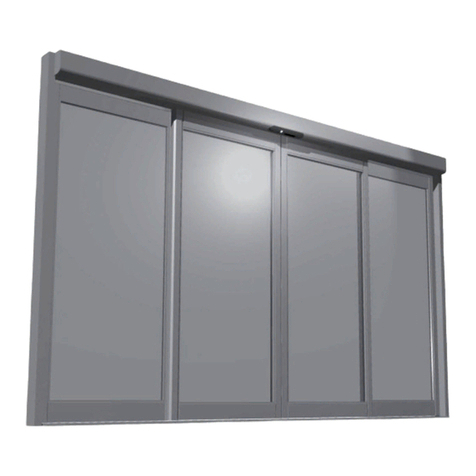
Blasi C 127 SU S User manual

Operating instructionsC 127 SU S 04/2013 Rev. BArticle no.: 121-127401297
Automatic
Under-floor Swing Door Operator
C127 SU S
Operating instructions
E
Page
1. General 2
2. Safetyinstructions 3
3. Technical data 4
4. Construction and function 5-6
5. Dimensions 7
6. Operating instructions 8 -10
7. Configurations 11 -12
8. Maintenance instructions 13
9. Action incase offaults 14 -18
10.Taking outofservice and disposal 19
11.Appendix 20
Blasi GmbH
Carl-Benz-Str. 5-15
DE-77972 Mahlberg
Phone +49 7822 893-0
Fax +49 7822 893-119

Page 2 of20 04/2013 Rev. B Operating instructionsC 127 SU S
1 General
These operating instructionsare intended forthe C 127 SU Sautomaticunder-floorswing doorop-
erator(herein afterreferred to asC 127). The operatoristhe person responsible forthe technical
maintenance ofthisdoorsystem.
These instructionsdescribe the use ofthe C 127 swing dooroperator. Theyformthe basisforsatis-
factoryfunctioning.
These operating instructionsshould be read bythe dooroperatorbefore commissioning and the
safetyinstructionsobserved!
It isrecommended to keep these operating instructionsclose to the automaticsliding door.
Productdesignation:Automaticswing door operator
Productname: C127 SUS
Serial number:
(please complete when installing)

Operating instructionsC 127 SU S 04/2013 Rev. B Page 3 of20
2 Safetyinstructions
The operatorhasbeen constructed in accordance with the latest state ofthe art and the recognised
technicalsafetyregulations, including limiting offorcesand speeds. Nevertheless, dangercan arise
forthe userifnot used asintended.
Installation, maintenance and repairs to the operatormust onlybe performed byquali-
fied and authorized personnel(technicians).
2.1Use as intended
The C 127 swing dooroperatorisconstructed exclusivelyfornormalservice with swing doors in dry
roomsand must be installed within orinside buildings. The stainless steelcasing with protection
class IP67 forthe insertion ofthe drive isusuallyembedded into the floor.
The dimension data indicated forproperinstallation must absolutelybe observed.
Adifferent application oruse extending beyond thispurpose isnot considered use forthe intended
purpose. The manufacturerdeclinesall responsibilityforresulting damage; the operatoralone shall
bearthe associated risk.
Use forthe intended purpose also includesobservation ofthe operating conditionsspecified bythe
manufacturer, including use and adjustment ofthe correct type ofarms, in addition to regularmain-
tenance and repair.
Unauthorised modificationsto the automaticdooroperatorwill exclude anyliabilityofthe manufac-
turerforresulting damage.
2.2General safetyand accidentprevention regulations
In generalno safetydevices(sensors) maybe dismantled orput out ofservice.
During the learning cycle(whichmustonlybe performed bytrained personnel)the
safetydevices(sensors) areswitched off!It mustbe ensured, therefore, beforeinitiat-
ing the learning cyclethat no personsorobjectsaresituated inthe dangerzone ofthe
moving doorleavesduring the operation in orderto avoid injuryordamage!
No objectsmust be placed in the opening zone / path ofthe swing doorto avoid crush-
ing and shearing points!
The safeguard forcrushing and shearing strainsat the side edge must be provided by
the manufacturer.

Page 4 of20 04/2013 Rev. B Operating instructionsC 127 SU S
3 Technical Data
Dimensions: 710 x200 x130 mm (stainless steelcasing LxBxT)
Operating voltage: 230VAC, 50/60 Hz
Powerconsumption: Standby13 W, rated power67 W
Max. torque: 50 Nm
Mass moment ofinertia: 65 kgm2 (C 127 SU S)
Opening angle: Adjustable from70°to 115°
Time delay: Adjustable from0 to 60 seconds(40 steps)
Opening speed: Adjustable from3 to 20 seconds(40 steps)
Closing speed: Adjustable from5 to 20 seconds(40 steps)
Noise emission: <45 dB
Protection class: IP67
Environment conditions
Temperature range: -15°to +50°C
Humidityrange: Up to 85%relative humidity, non condensing
Wind load:
3.1Door leaf weights and door widths
The curvesare calculated using to the following formula:
J=1/3 ×m ×b2
Standard arms: Jmax. 65 kgm2Key: J=mass moment ofinertia [kgm2]
Slide arms : Jmax. 65 kgm2m=doorleafweight [kg]
b =doorleafwidth [m]

Operating instructionsC 127 SU S 04/2013 Rev. B Page 5 of20
4 Construction and Function
4.1Construction
Keyto illustration:
1 Standard arm 11 Closing spring
2 Floorplate 12 Multifunctionalswitch MFon STG
3 Coverwith flat seal 13 STGcontrolunit
4 Drive C 127 incl. controlunit 14 STGconnection terminals
5 Stainless steelcasing 15 Motorprint MOT
6 Boxout forfloorinstallation 16 Slide switch S1 (rotation direction)
7 Adjusting screwforspring tension 17 ATEdrive unit terminals
8 Vision panel, adjust. spring tension 18 Mainsconnection terminals
9 Connectors forarms(both sides) 19 Fine-wire fuse
10 ATM drive unit 20 NETpowersupply
1
3
2
12
4
11
13
14
10
9
8
16
20
18
15
19
7
17
5
6

Page 6 of20 04/2013 Rev. B Operating instructionsC 127 SU S
Construction and Function
4.2Components
The C 127 swing dooroperatorformspart ofan electromechanicalswing doorsystemand com-
prisesthe following main components:
Control unitSTG: Intelligent, learning, microprocessor-controlled controlsystem.
Driving unitATE: Lowmaintenance DC geared motorwith electronicpath measure-
ment and integralthermostaticprotective switch, gearboxwith ad-
justable spring tension.
PowersupplyNET: Compact 230 Vpowersupplywith integralinput filterand over-
voltage protection.
Control unitBDE: Asrequired with convenient, simple mechanicalcontrolunit and / or
a programmable electronicBDE-D.
Armtypes: Powertransmission to the doorleafbyuse ofstandard armSG
pushing orsliding armGG pulling/pushing.
Locking VRR (optional): It ispossible to connect an electricaldooropener(24VDC)to the
operator.
Sensing units: Aestheticactuating and self-monitoring safetyelementswith adjust-
able sensitivityensure optimum, smooth and reliable operation of
the doorsystem.
4.3Functional description
In the standard "Automatic"mode ofoperation the doorsystemopensbythe response ofan actuat-
ing device (e.g. radarunit)to personsorobjectsapproaching. The doorclosesafterthe doorhold-
open time, provided no furtheropening pulse isreceived.
In the "Lock"mode ofoperation, the doorisonlyopened byactuation ofan optionalkey-operated
contact (SSK). The doorclosesafterthe SSK doorhold-open time, provided no furtheropening
pulse isreceived.
An obstacle to the swing doorleave during Closing leadsto an immediate re-opening (reverse).
The obstacle position isrecorded in the dooroperatorand thisposition isapproached slowlywhen
next closing. An obstacle to the swing doorleafwhen Opening resultsin an immediate stop.

Operating instructionsC 127 SU S 04/2013 Rev. B Page 7 of20
5 Dimensions
5.1Installation withboxout
5.2Operator instainless steel casing
Standardarm

Page 8 of20 04/2013 Rev. B Operating instructionsC 127 SU S
6 Operating instructions
6.1Controlson theSTG127
General
The STG127 operateswith an active HIGH level, i.e. a +24 Vlevelmust be applied to activate a
function. Safetyinputsare activated during interruptions.
The signalground (0V)isconnected to the protective earth.
Jumpers
J13: CAN line termination
J14: Master/ Slave
jumperat position M1 formaster(factorysetting)
jumperat position S1 forslave
LED’s
LD1: (red) ControlLED forpush-button operation (S1)
LD2: (green)+35V
Off forpowerfailure
LD3: (green)+24V
Lightsup if+24Vpresent.
Caution: in the event ofa powerfailure a processorreset
takesplace 1 second afterthisLED goesout.
Key(S1)
Thisisa multifunctionalkey.
The use ofthisswitch isreserved exclusivelyfortrained and authorized persons.
Top viewofthe controlunit STG:

Operating instructionsC 127 SU S 04/2013 Rev. B Page 9 of20
TOperating instructions
6.2Functionsofelectroniccontroller BDE-D(optional)
The BDE-D electroniccontrollerisan easilyoperated input
and output device forthe controland adjustment ofdoor
operators.
Logicallyarranged pushbuttonsallowintuitive operation
and navigation through the operator-specificmenu. The
LCD with backlight showsdata and information about the
doorstatuswith symbolsand text messages.
Additionalinformation can be found in the BDE-D manual.
6.3 Operation modes
Table ofsignals(Xmarksa release reaction)
Automatic/ AUTO
Normalfunction. The dooropensand closesautomatically, eitherbyactivating an actuating device
orbypushing the doorset on “Push to actuate”.
CLOSED OPENING OPEN CLOSING
AKI x x x x
AKA x x x x
SSK x x x x
SIO x x x
SIS x x
TIPP x
One-waytraffic/ EXIT
In one-waytrafficmode people cannot enterthe roomfromthe outside but theycan leave it from
the inside.
CLOSED OPENING OPEN CLOSING
AKI x x x x
AKA* x x x
SSK x x x x
SIO x x x
SIS x x
TIPP
*AKA isactive assafetydevice while closing

Page 10 of20 04/2013 Rev. B Operating instructionsC 127 SU S
Operating instructions
Manual operation / HAND
The doorcan be opened and closed byhand. The actuating devicesconnected are ignored.
Continuouslyopen/ OPEN
The doorisopened and staysopen. Ifan obstruction standsin the waywhile opening, the operator
triesanotherfive timeswithin a fewsecondsto bring the doorto the target open position. Should
the obstruction remain, the current position isthen validated asthe continuouslyopen position.
Locked
The locking isactivated in the Locked operation mode.
CLOSED OPENING OPEN CLOSING
AKI x x x
AKA x x x
SSK x x x x
SIO x x x
SIS x x
TIPP
Reset
Afterpushing on the button forapprox. 5sec. thisstatusmessage on the displayis:
No
Reset Operator?
Yes
Pushing again on the button resetsthe operator.

Operating instructionsC 127 SU S 04/2013 Rev. B Page 11 of20
7 Configurations
7.1Parameter Overview Factorysettings: Basicoperator (Full Power)

Page 12 of20 04/2013 Rev. B Operating instructionsC 127 SU S
Configurations
Configurationsofthe C 127 can onlybe made with the electronicBDE-D.
Furtherinformation forparameterchangescan be taken fromthe usermanualofthe BDE-D (no.
102-903109271).
Please alwaysleave the configuration reviewsheet in the drive!
7.2Parameter description
Parameter Setting
range Factoryde-
fault Description
DRIVINGCYCLE
Closing speed 0 -40
(5 -20 s) 18 Slidercontrolwith 40 steps
Opening speed 0 -40
(3 -20 s) 36 Slidercontrolwith 40 steps
DIN: >1.5 s<4 s
TIMEDELAYOPEN
Time delayopen 0 -40
(0 -60 s) 2 Effective with AKA, AKI and push to actuate
0 -20: Stepsof1 s
21 -40: Stepsof2 s
Time delaySSK 0 -40
(0 -60 s) 4 Effective with SSK
0 -20: Stepsof1 s
21 -40: Stepsof2 s
DRIVE
Opening angle 0 -40
(70 -115°) 35 The opening angle isestimated during the
calibration run and isequivalent to the value
of40.
DIN: min. 95°

Operating instructionsC 127 SU S 04/2013 Rev. B Page 13 of20
8 Maintenance instructions
8.1General
The C 127 swing dooroperatorisa product ofthe latest technology. It hasbeen carefullymade and
onlyleavesthe factoryfollowing thorough testing.
Automaticswing doors should be operated and maintained to ensure safetyat all times.
8.2Care
The entire swing doorsystemcan be cleaned with a damp cloth and commerciallyavailable cleaning
agents. The cleaning agent must be harmonised to the surface which hasto be cleaned.
It isrecommended to selectthe "Continuouslyopen"or"Locked"mode of operation forthispurpose, so
that the doordoesnot continuallyopen and close unnecessarily.
8.3Maintenance, periodicinspection
It isrecommended to have a technicalsafetytest with servicing performed bya specialist before first
commissioning and asrequired, but at least twice a year.
Regulartesting and servicing byourfullytrained personneltherefore offers the best guarantee fora
long service life and satisfactoryoperation. We therefore recommend the signing ofa maintenance
agreement. Ourservice department will be pleased to submit a proposal.
Ifnevertheless a fault should occur, which you cannot eliminate (see section 8)ourservice organisation
orthe maintenance personnelofouragentsare available.
8.4Acceptance ofhold-opensystem
Acceptance, testsand maintenanceshouldonlybe carried out byaspecialistoraperson
specificallytrained forthat. The authorization ofthesepersonsexclusivelylieswith the
manufacturerofthe hold-open system.Extent, resultsand timeof the periodicalinspection
must be recorded. These recordsmust be kept bythe operator.
8.5Service centres
In Switzerland: Phone +41 44 954 92 92 / Fax+41 44 954 92 00
Alternative service centre: _____________________________________________

Page 14 of20 04/2013 Rev. B Operating instructionsC 127 SU S
9 Action incase of faults
9.1 Faultindication
Variousindicationsare given foran irregularityorfault depending on the controlunit connected
BDE-EorBDE-M.
Whenusing anelectronicBDE-D
Information about the operatorsystem, like e.g. the software version, can be read out ofthe BDE-D
main displaybypressing the key.
Telephone number, fault and maintenance are onlydisplayed, when thisfunction hasbeen activated
bythe service technician.
Afterpressing thiskeyonce again, the phone numberofthe responsible service centre and the last
appeared fault indication isdisplayed in the screen. Ifthe fault message consistsofseverallinesthe
first line will be displayed only.
Press keyabout 2 seconds
Browse through informationsbytapping the key
Backto main displaybypressing the keyorautomaticallyafter20 seconds.

Operating instructionsC 127 SU S 04/2013 Rev. B Page 15 of20
Action incase of faults
9.2 Error displayand troubleshooting
Variousindicationsare given foran irregularityorfault depending on the controlunit connected BDE-
EorBDE-M. In case ofan anomalyin the operatorsystem, the standard screen ofthe BDE-D auto-
maticallyshiftsfromoperating mode to errordisplay. After2 seconds, displaychangesbetween
normal/ inverse.
Ifseveralerrors are active, theyare numbered:
Forinstance, error 1/2 meansthat the first one of2 errors isdisplayed.
Browsing through errordisplays:
Temporaryreturn to main displayfor4 secondsafterbrowsing through errordisplays.
9.3 Common error displays
The possible errormessagesare listed in the table belowaccording to theirnumberand together
with a problemdescription and data fortroubleshooting the errors and resetting the display. The
following abbreviationsand symbolsare used:
Abbrevia-
tion/
Symbol
Meaning
No. Statusorerrornumber
Reset Aservice technician isrequired forresetting the errordisplay. Afterremoving an error,
no automaticreset happens.
W Ifa “W”isdisplayed afterthe statusorerrornumber, it meansthat the erroron display
isa warning message and not an errormessage.
Despite the upcoming errorthe doorcan provisionallybe locked asfollows:
•Set BDE-D on MANUAL operating mode
•Set BDE-D on LOCKED operating mode
•Doorremainsclosed and locked

Page 16 of20 04/2013 Rev. B Operating instructionsC 127 SU S
Action incase of faults
No. Displaytext Reset Comments and possible troubleshooting
3 AKI >60sactive Inside radarlongerthan 60 sec. active and doorre-
mainsopen.
Checkthat no moving objectsare activating the radar.
Doorcan be locked with
5 AKA >60sactive Outside radarlongerthan 60 sec. active and doorre-
mainsopen.
Checkthat no moving objectsare activating the radar.
Doorcan be locked with
6 Unlocking error X Unlocking error: it isimpossible to unlockthe door.
Repeat unlocking attempt afterchanging the BDEop-
erating mode.
Ifdoorcannot unlock, checklocking device.
9 Opening unsuccessful
(after4 collisions) X Doordoesnot open oronlyslowly.
SIOmight possiblybe active ormotion be mechanically
hindered (e.g. dirt in floortrack). Checkthe interlock/
remove obstacle.
11 Faultymotorcurrent X Possiblyfaultywiring in prefabricated cables.
23 Slave controlunit
defective X Replacement byservice fitter.
25 Slave connection
(CAN)to Masterinter-
rupted
X Checkconnection via CAN insulator.
31 EMERGENCYSTOP EMERGENCYSTOPkeyhasbeen pressed, motor
relayde-energises
Reset byresetting the EMERGENCYSTOPbutton.
37 Motorcurrent X Faultymotorcurrent, motorisoverloaded. Possibly
STGorATEdefective.
38 Motoroverheat X Manualcontroleffective.
Doorleavespossiblytoo heavy, ortoo much friction.
Reset bymotorcooling down.
39 Overload 24V X 24 voltssupplyforperipheralunitsisoverloaded. Too
manyexternalunitspossiblyconnected orshort-
circuited, checkwiring.
40 Closing unsuccessful
(after10 collisions) X Doorleafmotion be mechanicallyhindered (e.g. dirt in
floortrack).
Checkthe interlock/ remove obstacle.
41 Temp. sensor1 X With motor1: temperature sensorisfaultyormotor
cable isdisconnected.
43 Encoderfault X Encoderorcable isfaultyornot plugged in.
Reset.
45 Motorcurrent -time
product to high Motorrelayde-energisesmanualcontroleffective.
Automaticreset bymotorcooling.
46 STGdefective X Controlunit isdefective. Includesthe following individ-
ualfaults: EPROM, RAM, Watchdog, Imax, ImaxT,
difference on SHE-EXT
Reset. Ifno success, then replace controlunit.
47 SIO>60sactive X Doordoesnot open orslidesat reduced speed. Verify
safetyelement SIO, auto-adaptation time longerthan
60sorfilterscreen iscovered orextremelydirty. Re-
move obstacle in the detection range ofthe sensor.
50 CPU2 isdefective Watchdog fault.
Load factorysettings. See error60. Replace control
unit.
51 Software version Software version ofMasterand Slave do not corre-
spond to each other. Software update byservice fitter

Operating instructionsC 127 SU S 04/2013 Rev. B Page 17 of20
Action incase of faults
No. Displaytext Reset Comments and possible troubleshooting
52 No running parameter X Doormust be calibrated (performteach-in run).
53 Interruption motor X Motorisnot plugged in. Motorisfaulty.
Afterwardsreset.
54 W Calibration run X Warning message:
Calibration run isperformed.
59 SIS>60sactive X Doordoesnot close.
Light barriers disconnected and doorremainsopen.
Checkthat safetybarriers are not covered orextremely
dirty. Checkthat the cabling to the sensorisnot inter-
rupted, the learning time islongerthan 60 sorthe filter
iscovered orextremelydirty. Possiblyremove any
obstacle fromthe presence detection area ofthe sen-
sor.
Doorcan be locked with
60 EEPROM defective X Load factorysettings. 9 light pulseswith MFTand reset
within 10 seconds. Afterwardslanguage selection has
to be displayed on BDE-D. Attention!All programming
are reset.
Reconfigure door.
Replace controlunit ifdoorstill failsto function.
61 SSK >60sactive Key-operated contact staysactive. Doorremainsopen.
ControlSSK-switch and wiring/connections.
Doorcan be locked with
62 W BDEhasno priority Cancelhigher-ordermode ofoperation. BDEislocked
e.g. bya time switch.
63 W Collision Doorcollision ordoorleafisstiff to operate. Possibly
remove anyobstacle fromthe moving area ofthe door
leaf.
72 Slave connection Masterhasno connection to Slave operator.
Checkconnection byCAN insulator.
Reset byservice fitter.
88 Difference parameter X The common parameters ofM/Soperators do not cor-
respond to each other.
Reset byservice fitter.
89 Masterconnection X Slave hasno connection to Masteroperator.
Checkconnection byCAN insulator.
Reset byservice fitter.
90 Rail beam>60sac-
tive Light beamin front ofthe doorforactivation AKA
(AUX2_IN)active longerthan 60 sand doorremains
open.
Checkthat safetybarriers are not covered orextremely
dirty.
91 Bodyguard >60sac-
tive SafetysensorBODYGUARD on input AUX1_IN active
longerthan 60 sand doorremainsopen.
Checkthat the cabling to the sensorisnot interrupted,
the learning time islongerthan 60 sorthe filteriscov-
ered orextremelydirty.
92 STGrelaydefect
X Change controlunit.
93 Overvoltage 24 V X Voltage <27 V. Wiring error. Checkconnections.
94 Spring calibration
Afterthe mech. adjustment ofthe spring tension the
calibration run must be performed.
95 Errorin sense ofrota-
tion X Checkposition ofslide switch S1.
96 EEPROM void X Load factorysettings. See error60.

Page 18 of20 04/2013 Rev. B Operating instructionsC 127 SU S
Action incase of faults
No. Displaytext Reset Comments and possible troubleshooting
97W Maintenance ex-
ceeded
X Warning message:
Actualvalue =105%oftarget value ofcyclesoroperat-
ing hours. Acknowledge message. Alarmisreset for13
days.
Informafter-salesservice and have installation ser-
viced.
98W Maintenance isdue
X Warning message:
Actualvalue =95%oftarget value ofcyclesoroperat-
ing hours. Repeat at 100%.
Acknowledge message. Alarmisreset fora short time.
Informafter-salesservice and have installation ser-
viced.
99W Operatorrotates X Rotate +lubricate function forgrease spreading in
gearboxhasbeen activated.
105W Test brake Automatictest onlyon operators with electromagnetic
brake.
106 Brake defective X Brake test wasunsuccessful. See error105.
107 SISdefective
X SISdefective
Asafetysensor(with test input)in closing direction is
defective.
Reset byservice fitter.
108 SIOdefective X SIOdefective
Asafetysensor(with test input)in opening direction is
defective.
Reset byservice fitter.
109 Factorysettings X
110 No motor
X No motordetection during initialisation (motortempera-
ture sensor).
Checkmotortemperature sensor.
Reset byservice fitter.

Operating instructionsC 127 SU S 04/2013 Rev. B Page 19 of20
10
Taking out of service and disposal
10.1
Taking outofservice
When the swing dooroperatorC 127 isdiscontinued ortaken out ofservice, it isdisconnected fromthe
powersupply.
Aftereverytemporarydiscontinuation, a newcommissioning hasto be carried out.
10.2
Dismantling and disposal
ATTENTION
All the partsofthe machine must be sorted bymaterialtypesand disposed ofaccording to
localregulationsand guidelines.
The swing dooroperatorC 127 installation can consist ofthe following materialsamong otherthings:
Aluminium:
•Chassisprofile, profilesofthe armsystem
•Gearbox
•Doorleaves
•Casing
•Variousprofilesand small parts
Steel and iron parts:
•Stainless steelcasing
•Floorplate
•Boxout forfloorinstallation
•Optionallyspacing orreinforcing profiles
•Gearboxcomponents, spring
•Varioussmall partslike fittings, covers, partsofthe armsystem, etc.
Non-ferrousmetals:
•Leveradapters, hard stop adapter
Glass:
•Doorleaves
Variouselectronical and electromechanical components:
•Controland operatorcomponents
•Sensors
Variousplastics:
•Cable clips, side caps, partsofthe coupling and the armsystem
•Sealing profiles
•Casingsofelectromechanicalcomponentsand sensors

Page 20 of20 04/2013 Rev. B Operating instructionsC 127 SU S
11
Appendix
11.1
StandardarmSG
11.2
Sliding armGG
Table of contents
Popular Door Opening System manuals by other brands
Karcher Design
Karcher Design EZ1060 Assembly instruction
Roger Technology
Roger Technology B73/EXP Instruction and warnings for the installer
Dormakaba
Dormakaba 8907 AF PKT installation instructions
Chamberlain
Chamberlain 883LM manual
B&D
B&D The Designer Series installation instructions
Dorma
Dorma 8600 IS manual
