Besam AAE977 User manual

Ultraview US23-0640-09 07-30-09 V4
© Copyright 2009 Besam US Inc. May not be reprinted without permission 1
Complies with ANSI/BHMA A156.10 Standard for Power Operated Pedestrian Doors. UL325 Listed
Besam UltraView
Installation Manual
AAE977

Contents
Important Information
Technical Specifications
Component Identification
Electrical Installation
Initial Sensor Setup
Mechanical Adjustments
Remote Control
1-Way Traffic Setup
Manual Setup
Troubleshooting
Retrofit Installation
Standard Inputs vs. Auxiliary Inputs
The Ultraview combines k-band microwave and focused active infrared technology to
provide superior activation and safety for the Unislide door system. For activation, the
unit provides digitally processed and sophisticated motion tracking technology for
unidirectional sensing when energy conservation is critical. For safety, the unit emits two
rows of 24 beams of focused presence technology that provides extraordinary safety in
and around the threshold Area. The active infrared curtains never shut off, even during
closing. Thus providing superior detection performance.
SPECIAL NOTE: The Ultraivew works differently than the BEA Wizard...
When making changes to the Ultraview reference the Ultraview users guide.
If you inadvertently make changes based on the BEA Wizard, you will cause
problems within the Ultraview system, which will result in callbacks.
Important notice!
To avoid bodily injury, material damage and malfunction of the product, the
instructions contained in this manual must be strictly observed.
Note!
Instructions, design, specifications and illustrations that are contained in
this manual are not binding. Rights reserved for changes without previous notice.
Environment
This operator may be equipped with batteries containing materials that are
hazardous to the environment. Remove the batteries from the operator before it
is scrapped. The batteries must be disposed of safely.
2
3
4
4
5-6
6
7-8
9
10
11
12-13
13
Product Overview
Important Information
Ultraview US23-0640-09 07-30-09 V4
© Copyright 2009 Besam US Inc. May not be reprinted without permission 2

Motion Sensor Presence Sensor
Technical Specifications
Description Specification
Supply voltage 12 to 24 VDC: -5% to + 10%
Power consumption <125 mA @24 VDC per sensor
Mounting height:
Standard
High
5’9” to 8’2” (1753 mm to 2489 mm)
8’2” to 13’ (2489 mm to 3962 mm)
Output
Motion Sensor
Optocoupled Transistor (Activation)
Max output current: 200 mA
Max switching power:48 VDC
Hold time 0.5 sec (fixed)
Presence Sensor
Optocoupled Transistor (Safety)
Max output current: 200 mA
Max switching voltage:48 VDC
Hold time 1 sec (fixed)
Monitoring P1: Test (0V)
P2: C-Switch
3-color LED
GREEN : motion detection
RED : presence detection
ORANGE : monitoring / error code
Temperature range -30°F to +131°F (-34° C to + 55° C)
Degree of protection NEMA 3S / (IP54)
Sensor dimension (exposed) 11.9” (302mm) L x 1.9” (48mm) W x 0.9”
(24mm) D
Weight 0.55 lbs / 250 g
Housing material ABS & LURAN S
Cable description:
Quick-disconnect Harness (sensor)
Short Extension Harness (black)
Long Extension Harness (gray)
1’ (300 mm), plug and play, 10-conductor
6’ (1530 mm), plug and play, 10-conductor
16’ (4580 mm), plug and play, 10-conductor
Product conformity R&TTE 1999/5/EC & EMC 89/336/EEC, FCC
Interface Factory Installed
Technology
Microwave and microprocessor
Transmitter frequency: 24.125 GHz
Transmitter radiated power: <20 dBm EIRP
Transmitter power density: < 5 mW/cm²
Focused active infrared with background track-
ing and self-monitored microprocessor
Spot diameter (standard) : 4” max
Number of spots : 24 or 12 spots by curtain
Number of curtains : 2
Detection field at 7’ (2130mm) mount height
Wide field
Narrow field
13’0” W x 6’6” D (3962 mm W x 1981 mm D)
6’6” W x 8’2” D (1981mm W x 2489 mm D)
6’6” W x 13.75” D (1981mm W x 349 mm D)
3’3” W x 13.75” D (991 mm W x 349 mm D)
Detection mode
Minimum detection speed
2 inches / sec. (measured in the sensor axis) Response time : < 128ms
Angular adjustments from 15° to 45° in elevation (adjustable) from - 4° to + 4° (adjustable)
Manual adjustment
Orientation of sensing field (mechanically)
Shape of the sensing field (choice of antenna)
Multiple functions (using push buttons).
Orientation of sensing field
Shape of the sensing field (choice of lens)
Multiple functions (using push buttons).
Remote control adjustments
Sensitivity
Detection mode
Immunity
Sensitivity
Auto-learn time
Ultraview US23-0640-09 07-30-09 V4
© Copyright 2009 Besam US Inc. May not be reprinted without permission 3

Component Identification
Electrical Installation
Connect the Extension Harnesses to the Ultraview Interface Board at the control as follows:
1. Designate the sensors as P1 or P2.
Important: The side of the door “not intended for use” when door is in one-way mode will be
designated P2.
2. The longer extension harness has a gray jacket and will be connected to the sensor on the
plank side. The shorter extension harness has a black jacket and is connected to the header
access side. Based on Step 1, connect the appropriate extension harness to the appropriate
connector on the Ultraview Interface Board.
Ultraview US23-0640-09 07-30-09 V4
© Copyright 2009 Besam US Inc. May not be reprinted without permission 4
MOUNTING SCREWS
INFRARED LENS
SHROUD
SENSOR
COVER
ULTRAVIEW
INTERFACE BOARD
QUICK DISCONNECT HARNESS(2 per system)
SHORT (black)
EXTENSION HARNESS
LONG (gray)
EXTENSION HARNESS
WIDE IR US21-0640-07
NARROW IR US21-0640-08
US02-0640-01
US21-0640-06
US02-0640-02
US02-0640-05
DIP SWITCH
STOP/IMPULSE(BREAKOUT INPUT)
P2
P1
STD/AUX SWITCH
KNOWING ACT INPUT (AUX)
US02-0640-04
US02-0640-03
Ultraview Replacement Sensor Kit -US15-0640-14
One assembled unit consisting of sensor, shroud, cover, wide lens, narrow lens,
mounting screws and quick disconnect harness.
(Not available as a spare part)

Intial Sensor Setup
1.Power up the Unislide and tune the door. (Unislide control V12.16.2 and above)
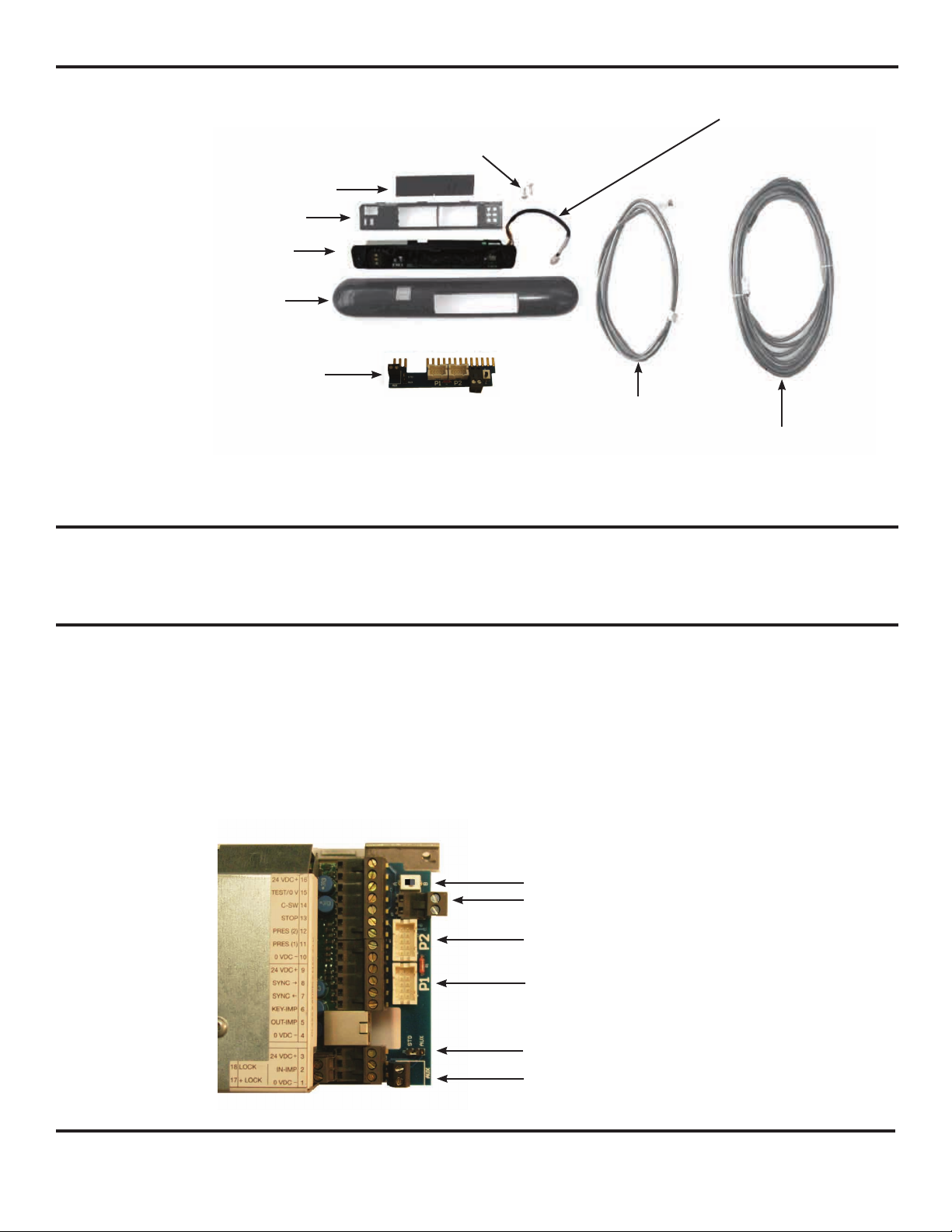
a.Remove the control cover and flip dipswitch #7 to OFF (down); turn the time
delay counterclockwise and disconnect the breakout switch terminal block and
keep P1/P2 disconnected.
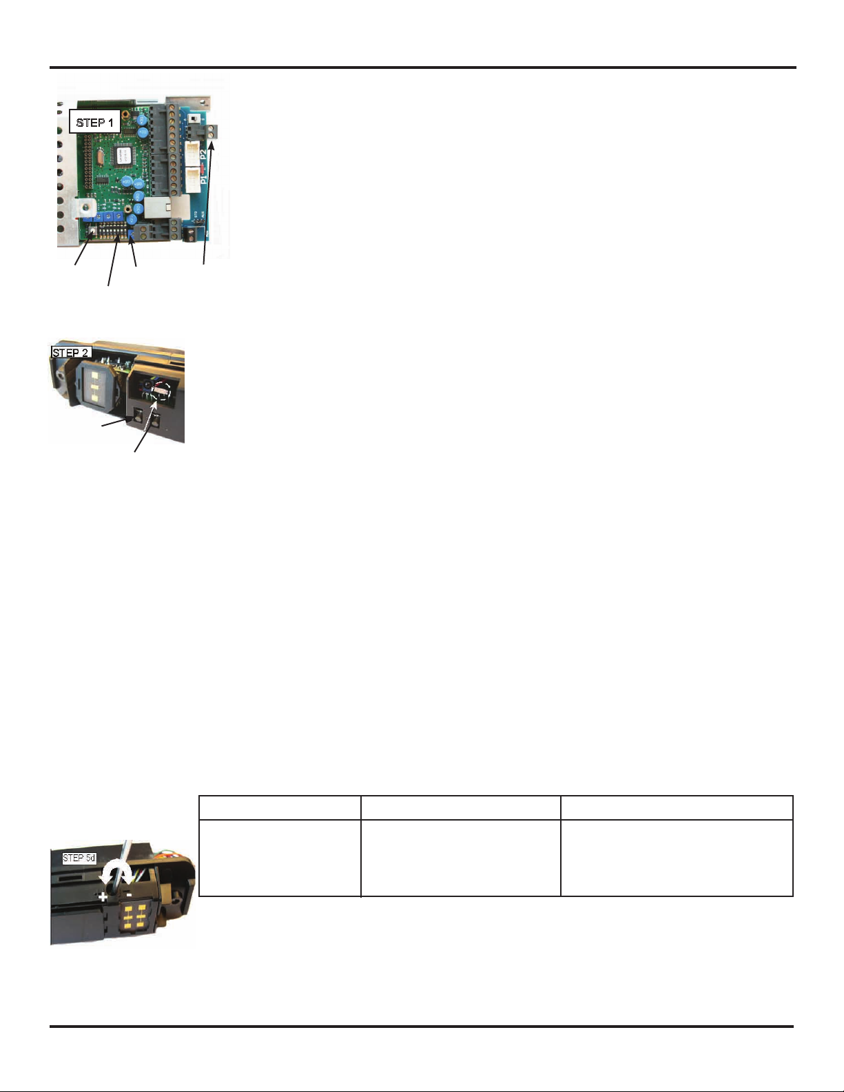
b.Slide door(s) closed and with the 5-position switch in Auto mode, press the
Learn button located on the bottom edge of the control. The door should cycle
slow open - slow closed.
c.Put the 5-position switch to Hold-Open and observe the door cycle for back
check functionality and make door adjustments if required and turn the time
delay to a minimum of 1.5 seconds.
d.Connect P1 and P2 (P2 = side not intended for use during a “1-way” traffic
mode) to the adapter board.
e.Open the Unislide cover and on the Unislide control box, flip dipswitch #7 ON
(for monitoring). Close the cover to the control box.
f.Close and latch Unislide cover. Set the rotary switch to the “Auto”, two-way
traffic position. Momentarily press the reset button located next to the 5-position
switch.
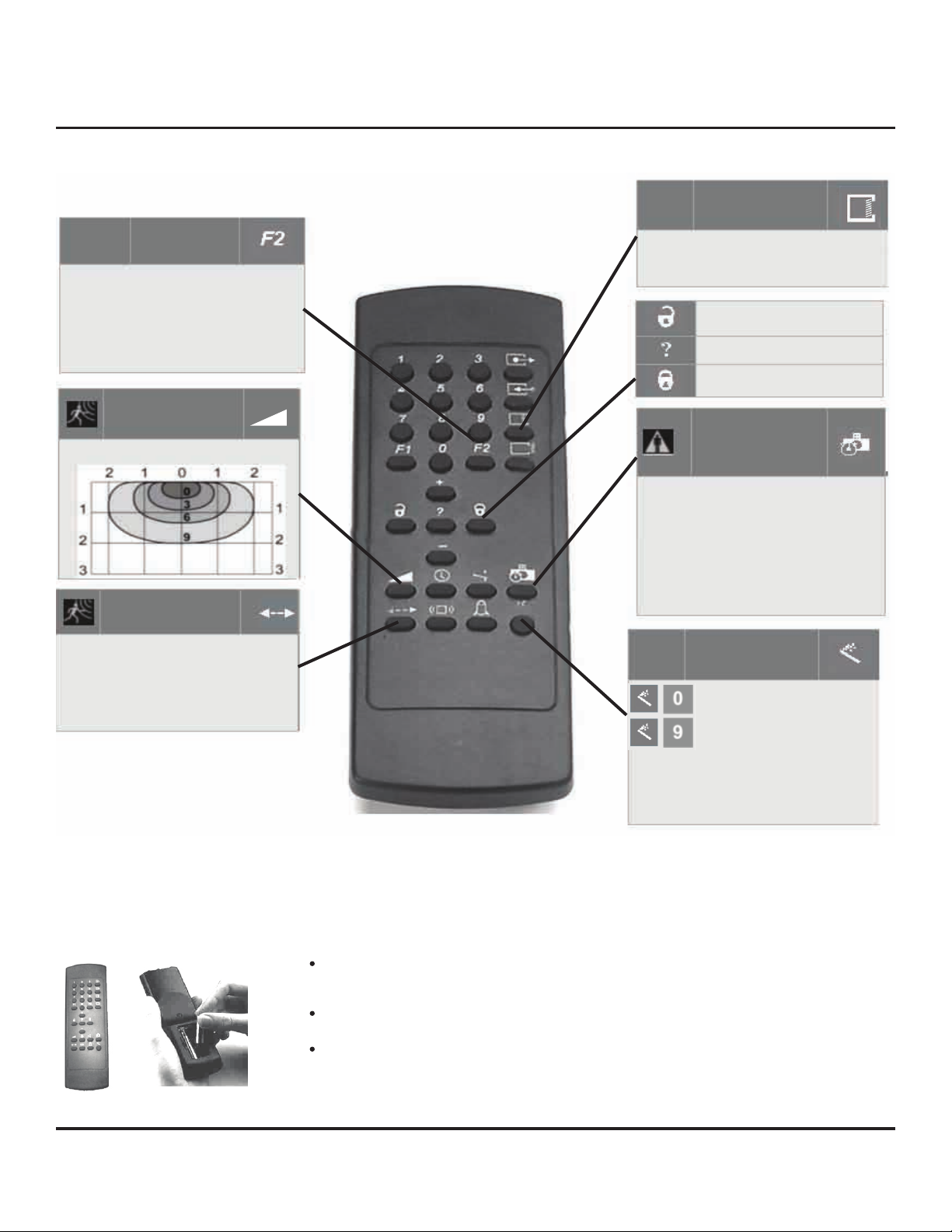
2.The Ultraview sensors are factory set in “Neutral” mode. To set up the system,
the sensors will need to be designated as P1 or P2, and then the sensors will need to
be configured for the particular installation. The system will not properly function until the
sensors are designated.
3.On the sensor to be designated as P1, confirm that it is connected to P1 at the interface
board then press the left push button for 3 seconds and release.The LED will flash green once
(meaning set to P1), and then steady red. The sensor will establish communication with the
other sensor and the LED on both sensors will flash slowly green (1 Hz) for 2 minutes
duration, and the other sensor will automatically be designated P2.
4.If the sensor is designated incorrectly, press and hold the left push button of the P1
sensor for 5 seconds and the sensor will return to neutral mode. The LED will flash green
three times when the push button is released. Then repeat step 2.
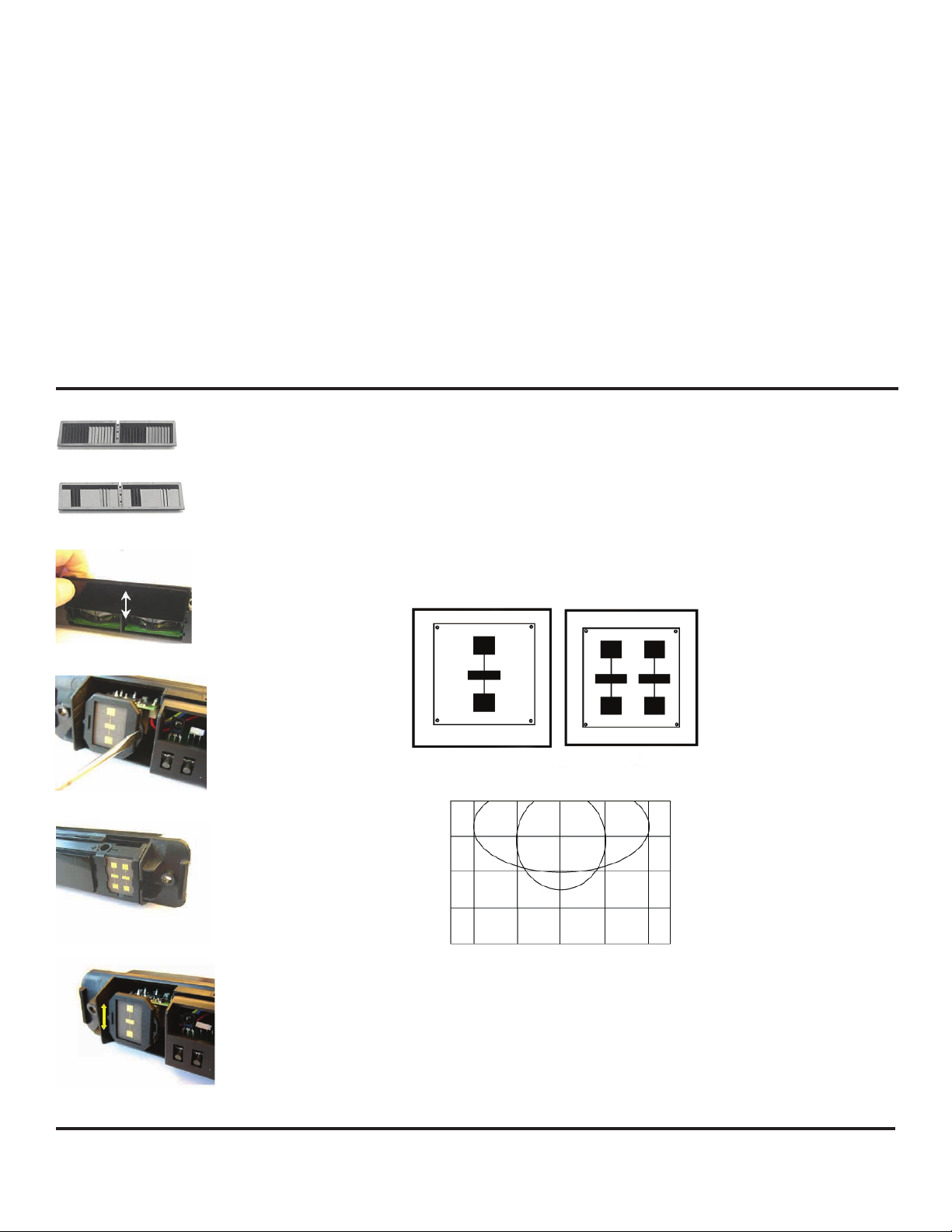
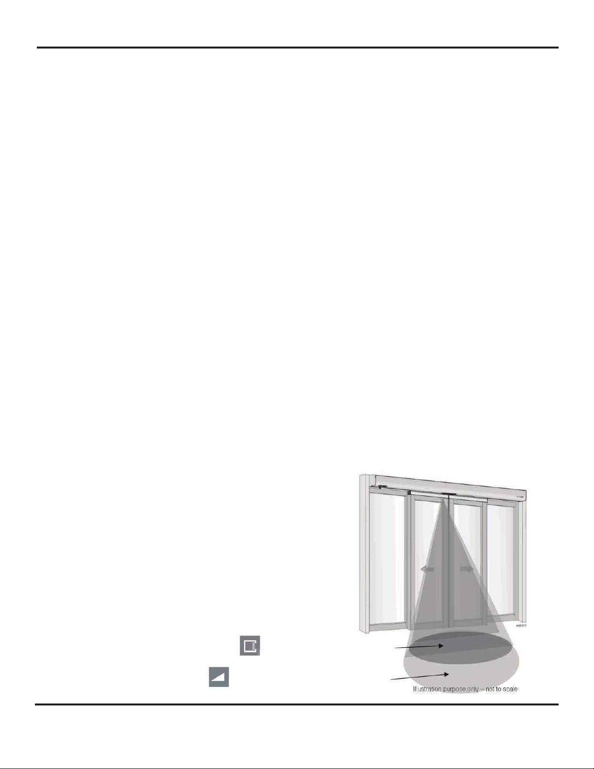
5.Mechanically adjust the presence field of each sensor for the installation.
a.Launch a setup of the system by momentarily pressing and releasing the right
push-button (on either sensor), and then step away from the pattern. This will
launch a setup for both sensors at the same time. Adjust one sensor at a time
thereafter. Keep traffic away from the sensor’s pattern.
If the right push-button is pressed for 3 seconds, the sensor will be in a
manual set-up mode. The sensor will flash red, then green a number of
times. To return to the standard mode press the right push button again for
3 seconds until the LED light stops flashing and then release.
b.The sensor will automatically go through a set-up and the LED will flash red/green
a number of times. The door will open, then close while the LED is flashing (the
sensors are learning the influence of the door) - this will take approximately
16 seconds
c.The LED will display one of four conditions:
d.If needed, turn the adjustment screw with a small screwdriver ½ revolution, then
repeat step 5a.
e.Repeat steps ‘a’ through ‘d’ for the other side of the door.
f.If any operator adjustments are made a new setup must be launched.
6.Connect the break-out switch connector (see picture Step 1) and secure the header cover.
7.(Once the Unislide and Ultraview covers are installed and secured in place). Launch a final
set-up via the remote control (magic wand 0)
Ultraview US23-0640-09 07-30-09 V4
© Copyright 2009 Besam US Inc. May not be reprinted without ermission 5
LED STATUS MEANING ACTION
(after pushing right pushbutton)
Rapid flashing RED
Rapid flashing Green
None
ORANGE
Presence pattern is too close to door
Presence pattern is too far from door
Presence pattern is properly positioned
ERROR
Adjust screw counterclockwise(+)
Adjust screw clockwise(-)
None
See Troubleshooting Guide on pg. 11
BREAKOUT
SWITCH
TIME
DELAY
DIP
SWITCH#7
LEARN
BUTTON
1.)PRESS LEFT
BUTTON
2.)OBSERVE LED
Note: Before connecting and tuning the sensors, complete all operator adjustments and verify
proper operation of the door system for compliance with applicable ANSI standards
STEP 1

1.Presence Field - To adjust the presence pattern width, install the desired
lens for the infrared curtain (presence), as shown below. Simply replace the lens by
sliding the new lens into the slot on the shroud. Narrow Lens is suitable for smaller door
openings or high-mounting applications. Most applications will warrant the use of the wide
pattern IR lens. The narrow lens should only be used for the narrowest door openings at
interior locations.
2.Motion Sensing Field - To adjust the microwave sensor’s pattern width (motion
detection), select the proper antenna to comply with applicable standards. Walk test the
area to confirm that there is appropriate level of activation. Refer to the diagram below for
approximation of field size for each pattern.
3.The position of the sensing field - is determined by the vertical angle of the planar
antenna. The angle is adjusted in 3 increments by gently rotating the antenna
forward or backward.The factory-set mounting angle is 30º . A 15º angle will result in
the pattern being drawn back towards the door, whereas the 45º will place the
pattern farther away. Be certain to walk-test detection field and insure compliance
with current applicable ANSI standards.
Ultraview US23-0640-09 07-30-09 V4
© Copyright 2009 Besam US Inc. May not be reprinted without permission 6
Mechanical Adjustments (Presence and Motion Sensing Fields)
NARROW-FIELD LENS
[3’3”(W)X13.75” (D)]
WIDE-FIELD LENS (FACTORY DEFAULT)
[6’6’(W)X13.75(D)]
CHANGE PRESENCE
LENS IF NEEDED
REMOVE BEZEL
OPTIONAL NARROW
ANGLE ANTENNA
ADJUST ANGLE BY
TILTING MICROWAVE CELL
7’-0” height= [13’(W) X 6’ 6” (D)] [6’ 6” (W) X 8’2” (D)]
Wide
Narrow
WIDE NARROW
Patterns shown in diagram
are those at 30° angle
6.4’ 3.2’ 0 3.2’ 6.4’
0
3.2’
6.4’
9.6’
8.When the Ultraview system acknowledges an internal fault, the sensor will make 3 additional
tests to confirm the fault. Overall, this takes approximately 45 seconds, after which, if the fault
is still present, the system will shut down in a safe state. It will then be necessary to power off,
then back on. If the fault is still present, the process will repeat itself. If the fault is cleared by
the power cycle, the system will return to normal operation. During fault acknowledgement, the
door will stay open following the first activation after the fault.
HELPFUL TROUBLESHOOTING HINT:
All door adjustments and door glass must be in place before final IR cutain set-up
Upon powering the Ultraview system, if sensors are properly programmed with
relation to P1 and P2, the sensors will display a momentary green LED that flashes once every
1 seconds (1Hz). This will continue for 2 minutes. If there is no momentary green flashing upon
powering, the sensor may be improperly programmed. When this occurs, the door, once open,
will remain open until the problem is resolved.
3.Upon a faulty setup, the affected sensor will be flashing a green or red LED. The flashing LED
will last for approximately 5 minutes, after which it will expire. It is absolutely necessary to
then launch another setup following the IR angle adjustment.

Ultraview US23-0640-09 07-30-09 V4
© Copyright 2009 Besam US Inc. May not be reprinted without permission 7
Adjusting Settings with Remote Control
Every programming session must begin by unlocking the sensor. Thereafter, a program
setting may be altered by pressing the desired function key, followed by the desired value
for that function. When all programming is complete, press the lock key twice to retain
settings. Use the following as a guide:
Setting up the Sensor with the Remote Control
The sensors can be programmed with the aid of the remote control.
To do so, perform the following:
1.With the P1 and P2 harnesses connected, apply main power to the Unislide control.
2.Unlock P1 with the remote control (be certain only P1 is unlocked):
a.Press the Unlock button (the LED will flash red quickly)
b.Press 0 (as a function key)
c.Press 1 (the LED will flash red slowly indicating communication)
d.Press lock twice (this will program the chosen sensor to a ‘P1’ designation)
3.Unlock P2 with the remote control:
a.Press the Unlock Button (the LED will flash red quickly)
b.Press 0
c.Press 2 (this will program the chosen sensor to a P2 designation)
d.Press lock twice
4.To check the sensor’s designation, unlock the sensor, and then press the number 1 or 2.
The LED will flash red slowly when the correct number is entered. After complete,
press lock twice.
5.Shut off main power to the Unislide - wait 5 seconds.
6.Re-apply power.
7.Unlock P1 (press unlock then 1).
8.Press magic wand on the remote control.
9.Press 0 - this will launch a set-up. Keep traffic away from the sensor’s pattern.
a.Sensor will flash red and green alternately
b.Both sensors will automatically go through a set-up
c.The door will open, then close while the LED is flashing (the sensors are
learning the influence of the door) - this will take approximately 16 seconds
d.To adjust properly, follow the instructions on page 5, section 5c
Unlock the sensor to enter into adjustment session
(if no access code has been entered). If a lock code is
present: the “1” for P1 or “2”, for P2 must be entered,
followed by the lock code.
To change the value of a parameter
(ex. Automatic learn time)
… to change any other parameters
(ex. Sensitivity)
To check the value of a parameter (ex. Automatic Learn
Time)
Lock the adjustment session and go back to normal
function
* the lock code may be one, two, three or four digits
long. If the lock code is less then 4 numbers, then the
code must be followed by the lock button to lock the sen-
sor.
Press Unlock
key
RED LED
flashes
1=P1
or
2=P2
RED LED
flashes
Select
parameter to
change
RED LED
flashes quickly
Enter new
value
RED LED
flashes slowly
Select
parameter to
change
RED LED
flashes quickly
Enter new
value
RED LED
flashes slowly
Select
parameter to
check
RED LED
flashes quickly
Press
Question
Mark
The number of
green flashes
indicate the
value of this
parameter
RED LED
flashes slowly
...
Press lock key twice
or + lock code*

Ultraview US23-0640-09 07-30-09 V4
© Copyright 2009 Besam US Inc. May not be reprinted without permission 8
Remote Control
The remote control provides ease of programming for the Ultraview. Make sure
the batteries in the remote control are charged - replace as necessary.
Open the battery compartment at the back of the remote control.
Insert 2 AAA batteries.
1:normal
(LED in normal mode)
2:door permanently open
(red LED ON)
3:door permanently closed
(red LED OFF)
Door Control
0(min)->9(max) default=7
Sensitivity
Microwave
Detection Mode
1:bidirectional mode
2:unidirectional mode
3:unidirectional mode with MTF
Setup
launch an assisted setup
restore factory settings
When restoring factory defaults(Magic
Wand+9), the sensor will self-launch a
setup, but will not change the designation
of P1 and P2
Automatic
Learn Time
0: 30 seconds
1: 1 minute
2: 2 minutes
3: 5 minutes
4: 10 minutes
5: 20 minutes
6: 60 minutes
9:Infinity - no learn
Re-entry Zone
1(min sensitivity)->9(max sensitivity)
Default=3
0 = off
Unlock
Check values
Lock
SPECIAL NOTE: In the event you believe the frequency needs changed
for your application please contact the Besam factory.

Ultraview US23-0640-09 07-30-09 V4
© Copyright 2009 Besam US Inc. May not be reprinted without permission 9
1-Way Traffic: Setting Up The Re-Entry Zone
The Ultraview sensor has a Re-Entry Zone function (see remote functions on Page 8) that
allows the User to define a secondary sensitivity level for the purpose of re-entry that is
independent of the normal microwave sensitivity. When using this function, the 0 value is off,
while the values of 1 through 9 are the sensitivity levels - 9 being maximum sensitiv-
ity. When at a value of 1 through 9, the secondary activation pattern is defined, and the output
from this zone is linked to the presence output from the sensor. Additionally, to aid
in the setup, the sensor’s LED will show red when the Re-Entry Zone is in detec-
tion.
By default, the Re-Entry Zone sensitivity is set to 3. This will need to be fine-tuned
per each application. To test the zone, perform the following:
1.Place the rotary switch on the header to a 1-way traffic mode.
2.Activate the door normally and proceed to the side not intended for use. Move to
about 5’ away from the door.
3.As soon as the door starts to close, walk slowly towards the Ultraview sensor.
4.As you walk towards the sensor, the LED will turn green to indicate motion
detection. However,the door will not re-cycle open at this time (it will continue to
close), because the motion output is going to the Outer Impulse at the control box,
which has been ignored due to the 1-way traffic selection.
5.Continue walking toward the door. As soon as the LED turns red, the door should
re-cycle open.The re-activation must occur at 24” or greater from the face of the sliding door.
6.If activation is at less than 24”, increase the Re-Entry Zone sensitivity and test
again. Be sure to test the zone from all approach angles to insure the following:
Detection pattern must extend out from the face of the door to 24” or greater, as
measured from the center of the clear door opening.
Detection pattern must extend for the full width of the clear door opening
Detection pattern must be within 5” of the face of the sliding door as measured at
the center of the opening.
7.Remember, when the rotary switch is in the 1-way traffic mode, activation from the
sensor at “the side not intended for use” will re-activate the door only if a detection is
realized by the Re-Entry Zone, or by the infrared presence zone.
8.Don’t forget to adjust normal microwave sensitivity for when the rotary switch is in
a 2-way traffic mode. When the switch is placed back to the 2-way traffic mode,
sensor indications will remain the same, however, activation from the normal
microwave detection
pattern will allow door
activation.
(1 through 9 value ) Re-Entry Zone
(0 through 9 value ) Normal microwave zone

Ultraview US23-0640-09 07-30-09 V4
© Copyright 2009 Besam US Inc. May not be reprinted without permission 10
Manual Set-up (without Remote)
In addition to the remote control, set-up of the parameters of the Ultraview may be done by
using the two sensor-mounted push buttons. The procedures below indicate how to program
using these buttons.
TO RESET THE UNIT TO FACTORY DEFAULTS including the access code
Press and hold both buttons simultaneously until both red and green
LED lights flash alternately.
TO ENTER INTO MANUAL SET-UP MODE
Press the right button for 3 seconds and release.
The LED will flash red, then green a number of times.
To return to standard mode:
Press the right button again for 3 seconds
until the LED light stops flashing and then release.
TO CHANGE PARAMETERS
The red LED light indicates the number for the parameter being altered
( 1 flash = parameter #1).
The green LED light indicates the value for the parameter being altered
( 1 flash means value = 1).
The right button enables selection of the parameter number being altered
( +1 for each press).
The left button enables alteration of the value
( +1 for each press).
EXAMPLE:Change radar sensitivity from 7 to 9 :
1.Press the right button for 3 seconds to enter the customizing mode
The green LED flashes once (parameter 1)
The red LED flashes 7 times (sensitivity = 7)
Press the left button twice to move from sensitivity = 7 to sensitivity = 9
Press the right button for 3 seconds to leave the customizing mode
NOTE:
1.When the highest value for the parameter has been reached, the
value will “roll over” to its lowest value
(e.g. for detection mode: 1, 2, 3, then 1, 2, …).
2.The sensor automatically returns to standard mode if neither button
has been pressed for one minute.
Manual Set-up (without Remote)
1 Radar Sensitivity 0-9 7
4 Automatic Learn Time 0-9 0
5 Detection Mode 1-3 3
11 Re-entry Zone 0-9 3
14 Door control function 1-3 1
Parameter Number
(altered by the right button
and confirmed by RED LED)
Parameter Values
(altered by the left button and
confirmed by GREEN LED)
Default Value
MANUAL
PUSH-BUTTONS

Troubleshooting
Red LED on at Ultraview. 1.Ultraview in detection.
1.Adjust infrared pattern away from the door
and launch a new set-up. Refer to page 3 for
infrared adjustments.
Door will not close
Red LED off at Ultraview.
1.On-Off switch at door control in
wrong position or is faulty.
2.Faulty door control.
3.Monitoring failed.
1.Ensure the On/Off switch for door is in the
ON or AUTOMATIC position. If switch is in cor-
rect position, check switch for proper operation.
2.Check door control.
3.Power off / on by pressing the reset
button next to the 5 position switch
Door will not open.
1.On-Off switch at door control in
wrong position or is faulty.
2.Ultraview not detecting traffic.
3.Faulty door control.
4.Door is broken out or there is a
faulty breakout switch
1.Ensure that On-Off switch for door is in ON
or AUTOMATIC position. If it is in correct
position, check switch for proper operation.
2.Walk in and out of Ultraview detection area,
if red LED does not illuminate check the power
supply for Ultraview: 12 to 24 VDC: -5%
to +10% (pins 1 and 2, wire color red and
black).
3.Remove all sensor inputs from the door
control. Jumper the common and activate
terminals of the door control. If door does not
open, fault lies within door control or motor.
Refer to manufacturer’s manual for further
troubleshooting. If door opens, fault lies with
sensors or related wiring.
4.Disconnect and test breakout switch
Door keeps recycling open
1.Ultraview is seeing door.
2.Ultraview is seeing movement
from unwanted objects.
3.Vibration is triggering the
Ultraview.
4.Door is binding on closing, thus
causing a reversing
1.Observe LED status on each Ultraview.
Green LED indicates motion detection, red
LED indicates presence. If LED’s are illuminat-
ing make sensor adjustments as necessary
to eliminate unwanted detection. Check angle
and sensitivity for presence and motion (see
pg6).
2.Check for moving objects in the path of
detection, such as posters, banners, etc.
3.Locate source of vibration and correct as
necessary.
4.Check for obstructions
Ultraview will not respond to
remote control.
1.Batteries in remote are dead or
are installed improperly.
1.Check to insure that the batteries are
installed correctly - observe polarity.
2.Replace batteries - AAA 1.5 volt.
Ultraview will not unlock when
access code is entered. 1.Improper code being entered.
1.Reset code to the default value of 0000 by
performing the following:
a.Cut and restore power supply. No code is
required to unlock during the first minute after
powering. Reset code prior to locking.
Solid orange LED
1.Sensor is in an automatic self
adaptation mode and cannot find
a new detection threshold, the IR
signal is saturated
DO NOT POWER OFF/ON
1.Remove objects too close to the door
(Installation Ladder)
2.Replace the narrow front lens by the wide
one
3.Change the IR curtain tilt angle slightly
4.Reduce floor reflectivity
Orange LED flashing
2 x per second
1.Sensor configuration corrupt
2.Internal system tests failed
1. Power Off /On by pressing the reset
button next to the 5 position switch
2. If problem reoccurs ->Replace Unit
Triple orange flash
every 1 minute
1. Sensor P1 or P2 is set to Neutral
and the other sensor is set to P1
or P2
1.Check electrical installation (pg4)
2.Check Sensor set-up (pg5)
Rapid flashing orange LED 1. System not properly set-up -
Time out
1.Power Off / On by pressing the reset
button next to the 5 position switch
2.Check Sensor set-up (pg5)
3.Check electrical installation (pg4)
Problem Probable Cause Corrective Action
Ultraview US23-0640-09 07-30-09 V4
© Copyright 2009 Besam US Inc. May not be reprinted without permission 11

Troubleshooting-continued (P1 and P2 related errors)
Green flashing LED (1Hz) on one sensor
only and the other sensor without LED
indication.Sensor will change to rapid
orange flash after a few minutes.
Both sensors indicate solid red LED
3 x orange flash then solid red on one
sensor, normal LED
indication on the other sensor, and door
stays open.
Fast flashing orange LED for a few min-
utes then solid red on one sensor, the
other sensor no LED indication
Wrong set-up of P1,programmed
sensor P1 does not match wire
connection P1 on the interface.
Both sensors programmed to P1 or
P2.
One sensor set to P2 and the other
to neutral.
One sensor set to P1 and the other
to neutral.
1)Reset system to neutral
2)Power Off / On by pressing the reset
button next to the 5 position switch
3)Select correct sensor with P1
1)Reset system to neutral
2)Power Off / On by pressing the reset
button next to the 5 position switch
3)Select correct Sensor with P1
1)Reset system to neutral
2)Power Off / On by pressing the reset
button next to the 5 position switch
3)Select correct Sensor with P1
1)Reset system to neutral
2)Power Off / On by pressing the reset
button next to the 5 position switch
3)Select correct Sensor with -P1
Problem Probable Cause Corrective Action
Mechanical Installation (for Retrofit Installations)
1. Separate the cover from the unit by prying apart the attachment clips.
2.Remove the shroud from the sensor by squeezing with
both hands on the shroud
Ultraview US23-0640-09 07-30-09 V4
© Copyright 2009 Besam US Inc. May not be reprinted without permission 12
PRY APART CLIPS
QUICK-DISCONNECT HARNESS
US02-0640-05
SQUEEZE SHROUD
TO REMOVE

3. Route the two connectors of the harness through the hole in the side of
the sensor and connect to the two headers on the circuit board.
4. Attach the sensor to the header using the two Phillips head screws being
careful that the sensor wires do not obstruct the mounting of the sensor base.
Then, replace the shroud on the sensor.
5. Repeat the installation procedure to the other side of the header.
6. Attach the cover to the sensor only after all mechanical adjustments are made.
Electrical Installation
The Ultraview Interface Board located at the front of the Unislide control has an option to
allow the input of a ‘Knowing Act’ device, such as push plates. The input device must have a
dry contact switch connected to this point. A small switch next to the input allows the User
to toggle between STD and AUX. The STD position is the default position. The AUX position
is selected for applications that require initial activation by the Knowing Act device only. Thus
when the switch is set to AUX, the initial activation must be provided by the push plate
(or otherwise), then once the door is at a position other than fully closed, the Ultraview
sensors will function with respect to the IR curtains, as well as according to the microwave
Standard Input vs. Auxiliary Input
1. Insert the Ultraview Interface Board into the Unislide Door Control and tighten all
of the screw terminals so that the Interface is securely fastened to the Control.
2. Insert the connectors from the sensor harnesses to the board as labeled (see page 4).
3. Set dip switch to position A. Position B is not active and will be used in future product
development.
Ultraview US23-0640-09 07-30-09 V4
© Copyright 2009 Besam US Inc. May not be reprinted without permission 13

Ultraview US23-0640-09 07-30-09 V4
© Copyright 2009 Besam US Inc. May not be reprinted without permission 14
patterns as defined by the Re-Entry Zone, as programmed by the remote control (see page
10 for the correct key). When using the AUX position, each Ultraview sensor must have the
microwave Re-Entry Zone configured to meet the requirements of a secondary activation
sensor.
The AUX input (when toggled to the AUX position) will be recognized by the control at any
Unislide On-Off switch position other than the OFF position.
For applications requiring a standard 1-way traffic mode, simply leave the Ultraview switch
in the STD position, and then place the Unislide On/Off switch (on the Unislide header access
cover) position to the 1-way traffic mode. The AUX input will not be acknowledged when
placed in the STD position.
KNOWING ACT:
TO PUSH PLATES
(DRY CONTACT ONLY)
DIP SWITCH
P1 P2 TO BREAKOUT
SWITCHES
1) Wire push plate to AUX input
2) Dip switch to AUX position
3) 5 position key switch to one-way
4) Set re-entry key on both sensors (24”)
1) Wire push plate to AUX input
2) Dip switch to AUX position
3) 5 position key switch to two-way
4) Set re-entry key on P1
Note: if key switch is set to one-way,
set re-entry key on P2 also.
(night mode)
1) Wire push plate to AUX input
2) Plate side sensor needs to be plugged
into P1 connector on interface
3) Dip switch to AUX position
4) Set sensor to neutral
5) Designate P1 sensor
6) Set 5 position switch to two-way
7) Set re-entry key on P1
2 push plate application 1 plate (cover side) 1 plate (plank side)
Example applications
Troubleshooting-continued (P1 and P2 related errors)
JUMPER

1.There are three different configurations available with the Ultraview System:
a.Full Time 1-Way Security:
Set STD-AUX switch to AUX position - this disables the P1 sensor during the door closed position.
Set rotary switch to 2-way traffic position
Connect the normally open and common dry contacts of the secure access device
(keyswitch, card reader, prox reader, etc.) to the AUX connector of the Ultraview interface.
Performance:
1.P1 will be disabled when the door is fully closed, but will be capable to provide detection for all
other door positions.
2.P2 will always be capable to create door activation, regardless of door position.
3.Setting the rotary switch to the OFF position will disable all inputs once the door is fully closed.
b.Full Time 2-Way Security:
Set STD-AUX switch to AUX position - this disables the P1 sensor during the door closed position.
Set rotary switch to 1-way traffic position - this will disable the P2 sensor during the door closed
position. Connect the normally open and common dry contacts of the secure access device
(keyswitch, card reader, prox reader, etc.) to the AUX connector of the Ultraview interface.
Performance:
1.P1 and P2 will be disabled when the door is fully closed, but will be capable to provide detection
for all other door positions.
2.A momentary contact closure at the AUX input will always be capable to create door activation,
regardless of door position.
3.Setting the rotary switch to the OFF position will disable all inputs once the door is fully closed.
c.Part Time 1-Way Security (Day-Night Mode):
Set STD-AUX switch to STD position.
Set rotary switch to 2-way traffic position.
Connect the normally open and common dry contacts of the secure access device
(keyswitch, card reader, prox reader, etc.) as follows:
1.Connect the Normally Open contact to the AUX terminal closest to the outer edge of the interface.
2.Connect the Common contact to the #2 (Inner Impulse) terminal of the interface.
Unplug the interface from the control
Loosen terminal screw #2 (Inner Impulse)
At the backside of the interface, insert a short wire (approx.6”)
Retighten terminal screw #2
Re-insert the interface into the Unislide control
Connect a second short wire to the outermost AUX terminal position as shown.
Performance:
1.P1 and P2 will operate normally while the rotary switch is in the 2-way traffic position.
There will be no secure access from either side.
Set rotary switch to 1-way traffic position -
2.The P2 sensor will be disabled during the door closed position.
3.P1 will continue to operate normally. P2 will become the secure side. Activation at the P2 side
must be initiated by a momentary closure of the secure access device.
4.Setting the rotary switch to the OFF position will disable all inputs once the door is fully closed.
Ultraview Security Applications
To secure access
drive
Ultraview US23-0640-09 07-30-09 V4
© Copyright 2009 Besam US Inc. May not be reprinted without permission 15

Ultraview US23-0640-09 07-30-09 V4
© Copyright 2009 Besam US Inc. May not be reprinted without permission 16
Planned Maintenance Checklist
To perform a proper Planned Maintenance inspection, you must follow the checklist below. Please
use your service tickets to note that this was done and record any
problems discovered and the action(s) taken.
1.Visually inspect door operation.
2.Check activation and threshold detection devices.
3.Check for tripping hazards.
4.Check door function switch.
5.Check for proper operation of lock assembly.
6.Check for required signage.
7.Check for loose glass stops or damaged glass.
8.Check all panels for damage and missing or damaged weather stripping.
9.Check panic latches for proper release force.
10.Check panic circuit operation for operator cut off or spring return.
11.Clean and inspect bottom guide tracks.
12.Check bottom guide assembly for proper adjustment and excessive wear.
13.Check door closing speed and closing force.
14.Check closing latch location.
15.Check that door hold open time is 1.5 seconds or longer.
16.Remove access cover and check motor and gearbox for leakage and noise.
17.Inspect drive pulleys and belt for proper alignment.
18.Inspect drive belt for proper tension and excessive wear.
19.Clean hanger rollers and repair or replace if damaged. Adjust roller height if necessary.
20.Clean roller track and remove any debris. (Do not lubricate track).
21.Inspect anti-riser block or rollers for damage and/or binding.
22.Insure that all wiring in the header is properly routed and protected from any
moving components.
23.Re-install and secure access cover and re-check the complete door operation.
24.Clean door, glass and header thoroughly.
25.Note on the Planned Maintenance review any recommendations to improve
door performance and reliability, and review with customer.
Besam US Inc.
1900 Airport Road
Monroe, NC 28110
Tel: (704) 290-5551, Fax: (704) 290-5555
Table of contents
Other Besam Door Opening System manuals