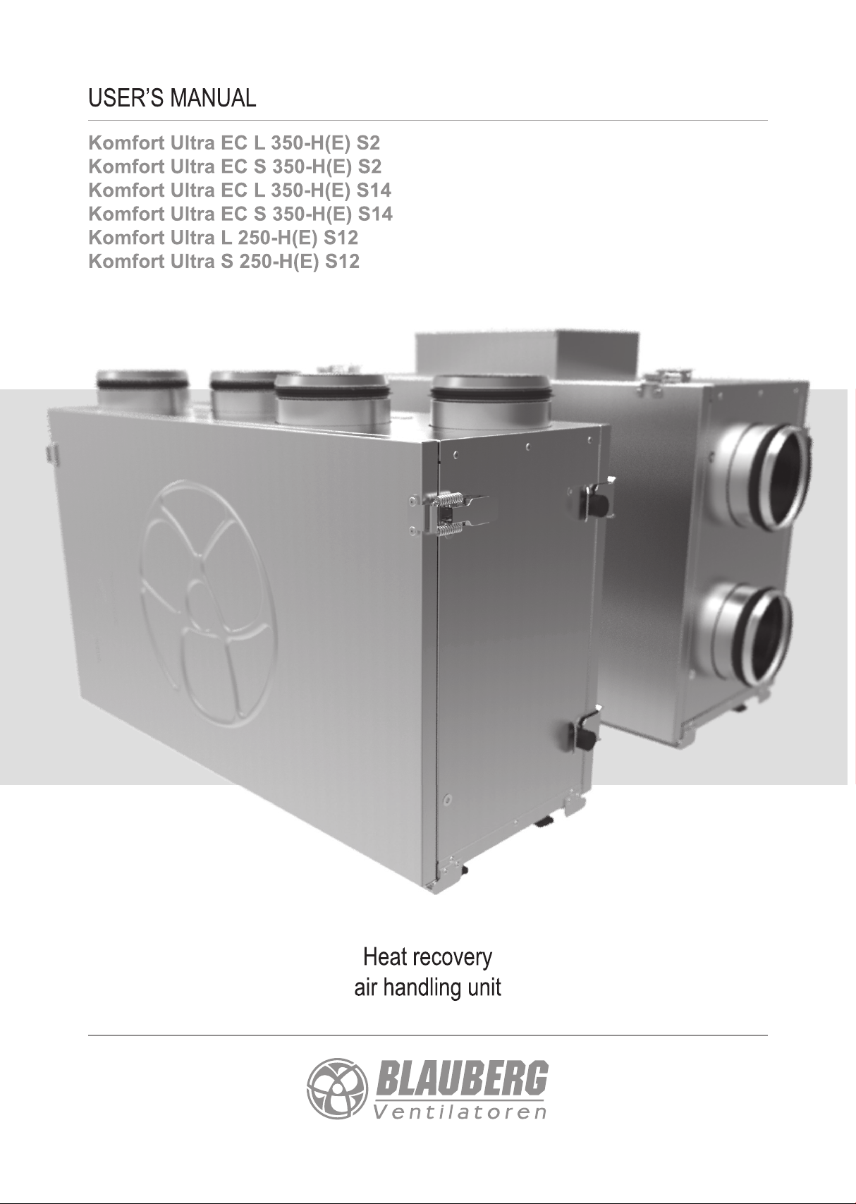
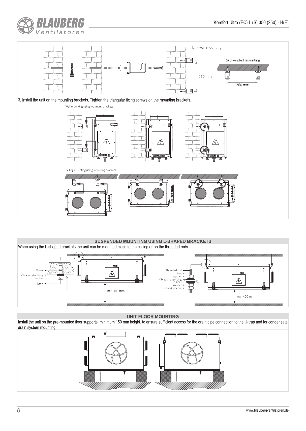
BLAUBERG Komfort Ultra Series User manual
Other BLAUBERG Air Handler manuals

BLAUBERG
BLAUBERG KOMFORT EC DB 160 User manual

BLAUBERG
BLAUBERG KOMFORT EC S S11 Series User manual

BLAUBERG
BLAUBERG Micra 100 WI-FI User manual

BLAUBERG
BLAUBERG Freshbox 200 ERV WiFi User manual

BLAUBERG
BLAUBERG KOMFORT ERV EC DB100 S14 User manual

BLAUBERG
BLAUBERG KOMFORT EC D5B 180 User manual

BLAUBERG
BLAUBERG Freshbox 100 User manual

BLAUBERG
BLAUBERG KOMFORT EC Series User manual

BLAUBERG
BLAUBERG KOMFORT EC S160 User manual

BLAUBERG
BLAUBERG Freshbox 100 WiFi User manual

BLAUBERG
BLAUBERG VENTO Expert A50-1 W User manual

BLAUBERG
BLAUBERG VUT 270 V5B EC User manual

BLAUBERG
BLAUBERG Komfort EC D5B180 S14 User manual

BLAUBERG
BLAUBERG CIVIC EC DB 300 V.2 User manual

BLAUBERG
BLAUBERG KOMFORT EC LB User manual

BLAUBERG
BLAUBERG KOMFORT EC S5B 270 User manual

BLAUBERG
BLAUBERG Reneo-Fit D 100 S14 User manual

BLAUBERG
BLAUBERG KOMFORT Ultra D105-A User manual

BLAUBERG
BLAUBERG Freshbox 100 WiFi User manual

BLAUBERG
BLAUBERG FRESHBOX E120 User manual


Popular Air Handler manuals by other brands

Klimor
Klimor EVO-S Operation and maintenance manual

Salda
Salda SMARTY XP MOUNTING AND INSTALLATION INSTRUCTION

Trenton
Trenton TPLP Series installation instructions

Kemper
Kemper CleanAirTower operating manual

Daikin
Daikin DV PTC 14 Series installation instructions

Haier
Haier HB2400VA1M20 Installation & operation manual

Webasto
Webasto BlueCool A-Series operating instructions

RDZ
RDZ DA 701 Technical installation manual

Carrier
Carrier 39T Installation, Start-Up and Service Instructions

Armstrong Air
Armstrong Air BCE5V Series installation instructions

ActronAir
ActronAir CAY500T Installation and commissioning guide

Carrier
Carrier 40MBDAQ Service manual

Allied
Allied A93UH1E Service manual

Nortek
Nortek B6VMAI installation instructions

TemperZone
TemperZone Econex Pro OPA 1410RLTM4FPQD Installation & maintenance

RDZ
RDZ WHR 200 Technical installation manual

AAON
AAON H3 Series Installation operation & maintenance

Lennox
Lennox VEOA042N432U Installation & operation instructions