Blaze CBL523-PAS User manual

INSTALLATION MANUAL
CBL523-PAS Loudspeakers

1. Introducon and Overview
1.2 CBL523-PAS Pack Contents
Each CBL523-PAS package contains a single loudspeaker and its
document pack.
1.3 CBL523-PAS Mounng, coupling and ying
accessories
The accessories illustrated below are oponally available to
enable CBL523-PAS loudspeakers to be wall or ceiling mounted,
own, or coupled in pairs.
CBL523-PAS
loudspeaker CBL523-PAS
Mounng Bracket
CBL523-PAS
Flying and Coupling Accessories
1.1 Introducon
Thank you for purchasing the Blaze Audio CBL523-PAS loudspeaker. The CBL523-PAS is a compact constant
direcvity, full range loudspeaker designed for installaon in venues that require a versale, short throw, high quality
public address loudspeaker soluon. Mounted in landscape format, the CBL523-PAS provides 15° vercal and 160°
horizontal coverage with maximum connuous sound pressure level of 119dB at 1m.
The CBL523-PAS incorporates mulple aachment points that enable a variety of ceiling mount, wall mount and own
installaons. A ceiling or wall mount bracket, ying hardware, and coupler straps that enable two loudspeakers to be
fastened together in a yable array are oponally available.
The CBL523-PAS comprises a low frequency array of two high performance 5 inch drivers operang from 71Hz to 520Hz, combined
with a vercal line source wide band array of three 2 inch drivers operang from 520Hz to 18kHz. CBL523-PAS loudspeakers are
designed to be driven by Blaze PowerZone Connect power ampliers congured to provide appropriately ltered equalized outputs.
Document Pack

2. Applicaons and Deployment
• Read these instrucons.
• Keep these instrucons.
• Heed all warnings.
• Follow all instrucons.
• Before installing or suspending any CBL523-PAS loudspeaker,
inspect all hardware, the enclosure, and associated equipment
for damage. Missing, corroded, or deformed components, or
components without correct load rangs, could signicantly
reduce the strength of the installaon or placement and should
immediately be repaired or replaced.
• Always make sure that the structure the loudspeaker is to be
suspended from has been approved by the building or structural
engineer and will support the weight of all the components
of the speaker system including speakers, speaker cable, wire
rope, etc.
• Consult a licensed professional structural engineer regarding
physical equipment installaon.
• Do not suspend loudspeakers directly over people.
• Use only hardware that is rated for the load condions of
the installaon and that allows for a possible short-term,
unexpected overload. Never exceed the rang of the hardware
or equipment.
• Blaze Audio strongly recommends that the system be inspected
at least once a year and logged. If any sign of weakness
or damage is detected, remedial acon should be taken
immediately.
• All installaon crew members must be trained for loudspeaker
rigging and mounng.
• Make sure that all relevant health and safety regulaons
are known, are followed by the installaon crew, and follow
applicable local laws. Local government oces can help with
this informaon.
• Suspended installaons must be completed or supervised by a
cered rigger.
• The system should be designed so that it is a stac suspension.
There should be no dynamic or shock loading.
• Personal protecve equipment (hard hats, steel-toed footwear,
safety glasses, etc.) should be always worn by the installaon
crew.
• If called for in the design, make sure all installaon personnel
are trained to work at height and have cercaons for scissor
lis, theatrical hoists, etc.
• Make sure all liing equipment (slings, span-sets, deck chain,
scaolding, etc.) is in good working order. Thoroughly inspect all
components prior to use.
• Inspect all the components associated with the project
for damage before assembly. Any parts with damage or
suspected damage should not be used. Contact the component
manufacturer for replacement parts if necessary.
• Keep a dy workplace. Do not leave tools, rigging items, etc., on
top of loudspeakers during installaon. Loose items can fall and
cause injury.
• Never leave the system unaended during the installaon
process. Make sure that the workspace is isolated from
public access. No one should be allowed to pass beneath the
loudspeakers during installaon.
• Do not suspend any other components or loudspeakers other
than the supported conguraons described in this manual.
• If secondary steel safees are required, they should be installed
once the enre system is at operang height and before public
access is allowed.
2.1 Important Safety Instrucons
WARNING: Failure to observe the following safety precauons may result in severe injury or death.
Installaons such as described in this guide should only be aempted by a trained professional.

2. Applicaons and Deployment
2.2 Installaon Opons
CBL523-PAS loudspeakers can be wall or ceiling mounted, or own in either singles or pairs. These installaon opons
are illustrated and described in the following secons.
2.2.1 Wall Mount Installaon
CBL523-PAS loudspeakers can be wall mounted using the
Blaze CBL523 Mounng Bracket. To use the bracket proceed
as illustrated and described in the following paragraphs and
diagrams.
Note: It is important to ensure that any structure to which a
CBL523 loudspeaker is mounted is able to support its weight with
an appropriate factor of safety. The ngs and screws used must
also be appropriate for the type of building construcon. If there is
any doubt in either respect, a specialist structural engineer must be
consulted.
Step 1. Select the required wall mount locaon and secure the
Mounng Bracket using three appropriate screws and
wall xings. Use at or pan head screws with a minimum
shank diameter of 8mm (5/16 inch) and a minimum head
diameter of 12mm (1/2 inch).
2. Remove the side panel
aachment screws.
3. Adhere a rubber washer to
each side of the loudspeaker.
4. Use the accessory
kit screws to secure
the loudspeaker to the
Mounng Bracket.
Rubber washer.
One each side
Step 2. Remove the aachment point screws located in the
loudspeaker side panels.
Step 3. Idenfy the rubber washers in the Mounng Bracket
accessory pack. The washers are self adhesive on one side
and should be adhered to the sides of the loudspeaker at
the screw posions. One washer is required for each side
of the loudspeaker.
Step 4. Aach the loudspeaker to the Mounng Bracket using
the M6x35 screws included in the Mounng Bracket
accessory pack inserted through the slot holes in the
bracket. Adjust the mounng locaon in the slot length
and the mounng angle as required then ghten the
screws so that the rubber washers are compressed to
secure the loudspeaker.
1. Use three screws to
secure the Mounng
Bracket at the required
locaon.

2.2.2 Ceiling Mount Installaon
CBL523-PAS loudspeakers can be ceiling mounted using the
Blaze CBL523 Mounng Bracket. To use the bracket proceed
as illustrated and described in the following paragraphs and
diagrams.
Note: It is important to ensure that any structure to which a
CBL523 loudspeaker is mounted is able to support its weight with
an appropriate factor of safety. The ngs and screws used must
also be appropriate for the type of building construcon. If there is
any doubt in either respect, a specialist structural engineer must be
consulted.
Step 1. Select the required ceiling mount locaon and secure the
Mounng Bracket using three appropriate screws and
xings. Use at or pan head screws with a minimum shank
diameter of 8mm (5/16 inch) and a minimum head diameter
of 12mm (1/2 inch).
2. Applicaons and Deployment
3. Adhere a rubber washer to
each side of the loudspeaker.
Rubber washer.
One each side
1. Use three screws to secure the
Mounng Bracket at the required
locaon.
2. Remove the side panel
aachment screws.
Step 2. Remove the aachment point screws located in the
loudspeaker side panels.
Step 3. Idenfy the rubber washers in the Mounng Bracket
accessory pack. The washers are self adhesive on one side
and should be adhered to the sides of the loudspeaker at
the screw posions. One washer is required for each side
of the loudspeaker.
Step 4. Aach the loudspeaker to the Mounng Bracket using
the M6x35 screws included in the Mounng Bracket
accessory pack inserted through the holes in the bracket.
Adjust the mounng angle as required then ghten the
screws so that the rubber washers are compressed to
secure the loudspeaker.
Note: The Mounng Bracket slot holes are not intended for ceiling
mount applicaons.
4. Use the accessory kit screws
to secure the loudspeaker to
the Mounng Bracket.

2. Applicaons and Deployment
WARNING: Consult a professional mechanical or structural engineer, licensed in the jurisdicon of the
sound system installaon, to review, verify, and approve all aachments to the building or structure.
Employ the services of a cered, professional rigger for hoisng, posioning and rigging the equipment
to the supporng structure. Improper suspension can lead to serious damage, injury, or death.
NEVER SUSPEND LOUDSPEAKERS DIRECTLY ABOVE THE AUDIENCE
2.2.3 Flown Installaon
CBL523-PAS loudspeakers can be own using the Flying Beam
component from the CBL523-PAS Flying and Coupling accessory
kit. To aach and use the Flying Beam proceed as illustrated and
described in the following paragraphs and diagrams.
Step 1. Invert the loudspeaker and remove the four Flying Beam
aachment screws. Retain the screws.
Step 2. Place the Flying Beam in posion on the loudspeaker and
1. Invert the loudspeaker
and remove the four
Flying Beam aachment
screws.
2. Place the Flying Beam
on the loudspeaker
secure it with the screws
removed in Step 1.
secure it with the screws removed in Step 1. Use all four screws.
With the Flying Beam secured, the loudspeaker can be aached
to ying hardware. Use at least two aachment holes in the
Flying Beam

2. Applicaons and Deployment
2.2.4 Loudspeaker Arrays
Two CBL523-PAS loudspeakers can be coupled together to
create a yable array that oers 30° vercal coverage. To couple
two loudspeakers, use the Flying and Coupling accessories and
proceed as illustrated and described in the following paragraphs
and diagrams.
Note: It is not possible to use the wall or ceiling Mounng Bracket
with a coupled loudspeaker array.
Step 1. Aach a Flying Beam, as described in Secon 2.2.3, to
the (inverted) loudspeaker that is to be the upper element in the
array.
Step 2. Place the upper loudspeaker with the Flying Beam ed
on top of a second non-inverted loudspeaker and remove the
aachment point screws located in the loudspeaker side panels.
Retain the screws.
Step 3. Use the screws removed in Step 2 to secure a Coupling
2. Remove the
loudspeaker side panel
aachment screws.
3. Secure a Coupling
Strap to each side of the
loudspeaker.
Strap to each side of loudspeaker array. With the loudspeaker
array constructed it an be aached to ying hardware. Use at
least two aachment holes in the Flying Beam
WARNING: Consult a professional mechanical or structural engineer, licensed in the jurisdicon of the
sound system installaon, to review, verify, and approve all aachments to the building or structure.
Employ the services of a cered, professional rigger for hoisng, posioning and rigging the equipment
to the supporng structure. Improper suspension can lead to serious damage, injury, or death.
NEVER SUSPEND LOUDSPEAKERS DIRECTLY ABOVE THE AUDIENCE

3. Connecon and Amplicaon
3.1 CBL523-PAS Connecons
The CBL523-PAS is ed with a two Neutrik NL4 Speakon sockets on its rear panel for connecon to an appropriate
Blaze PowerZone Connect Amplier and oponal parallel output connecon to a second CBL523-PAS loudspeaker.
Input and output connecons are described and illustrated below.
CBL523-PAS Socket Connecons
Signal Roung Connecon Pin
System (-) 1 (-)
System (+) 1 (+)
3.1.1 CBL523-PAS Connecons
The CBL523-PAS connecon sockets are congured as indicated
in the following table and diagrams. The two sockets are wired
in parallel to enable the connecon of a second CBL523-PAS
loudspeaker when, for example, two are coupled in an array as
described in Secon 2.2.4.
Connect to Blaze
PowerZone Connect
amplier output
Oponally connect to
second CBL523-PAS
1-
2+
1+
2-
Neutrik Speakon NL4 Pins
System
posive (+)
System
negave (-)
UnusedUnused

1-
2+
1+
2-
1-
2+
1+
2-
1-
2+
1+
2-
1-
2+
1+
2-
3. Connecon and Amplicaon
3.1.2 CBL523-PAS Amplier Connecons
CBL523-PAS loudspeakers are intended to be paired with
Blaze PowerZone Connect 252 or 504 power ampliers. These
amplier models incorporate the DSP equalisaon facilies
required to opmise the CBL523-PAS acousc performance,
while also providing appropriate output power capabilies. The
PowerZone Connect 252 and 504 ampliers are two and four
output units respecvely.
Note: It is possible for each PowerZone Connect amplier output to
drive two CBL523-PAS loudspeakers, however this conguraon is
not recommend for anything beyond medium duty applicaons at
modest sound pressure levels.
CBL523-PAS loudspeaker and PowerZone amplier connecons
are illustrated in the diagram alongside.
Note: No more than two CBL523-PAS loudspeakers must be
connected to each amplier channel.
Note: The Blaze PowerZone Connect Installaon Manual, available
for download from the Blaze website (blaze-audio.com), contains
comprehensive amplier installaon and operaonal informaon.
1-
2+
1+
2-
1-
2+
1+
2-
1-
2+
1+
2-
1-
2+
1+
2-
Oponally connect
further CBL523-PAS
Oponally connect
second CBL523-PAS
3. Connecon and Amplicaon
3.2 PowerZone Connect Amplier Equalizaon Proles
The Blaze PowerZone Connect amplier incorporates DSP based loudspeaker equalizaon, accessed via a web page
interface, that enables precongured lter and equalizaon presets to be applied to speaker outputs. A preset for
CBL523-PAS loudspeakers is available for download from the Blaze website and must be used for correct loudspeaker
performance. The procedure for downloading and applying loudspeaker presets is described in the following
paragraphs.
3.2.1 PowerZone Control Network Connecon
In order to install the CBL523-PAS speaker preset les, the
PowerZone Connect amplier requires either a wired or wireless
connecon via a TCP/IP network, or to connect via its own
wireless access point, to a computer or mobile device from which
speaker preset les can be uploaded. Internet access for speaker
preset le download is also required.
Note: The PowerZone Connect amplier Quick Start Guide and
Installaon Manual documents cover network connecon and can
be downloaded from the Blaze website: hps://blaze-audio.com/
support/#Manuals
3.2.2 Speaker Preset Download and Applicaon
Follow the steps below to download and apply the CBL523-PAS
speaker preset to required amplier output or outputs.
Step 1. Using a computer or mobile device, visit the Blaze website
(blaze-audio.com/products/speakers/cca10/) and select
the speaker preset les for download.
NOTE: The speaker preset
les will download in a
compressed .zip archive
format. Expand the .zip
archive and store the les in
an appropriate locaon on
the download device.
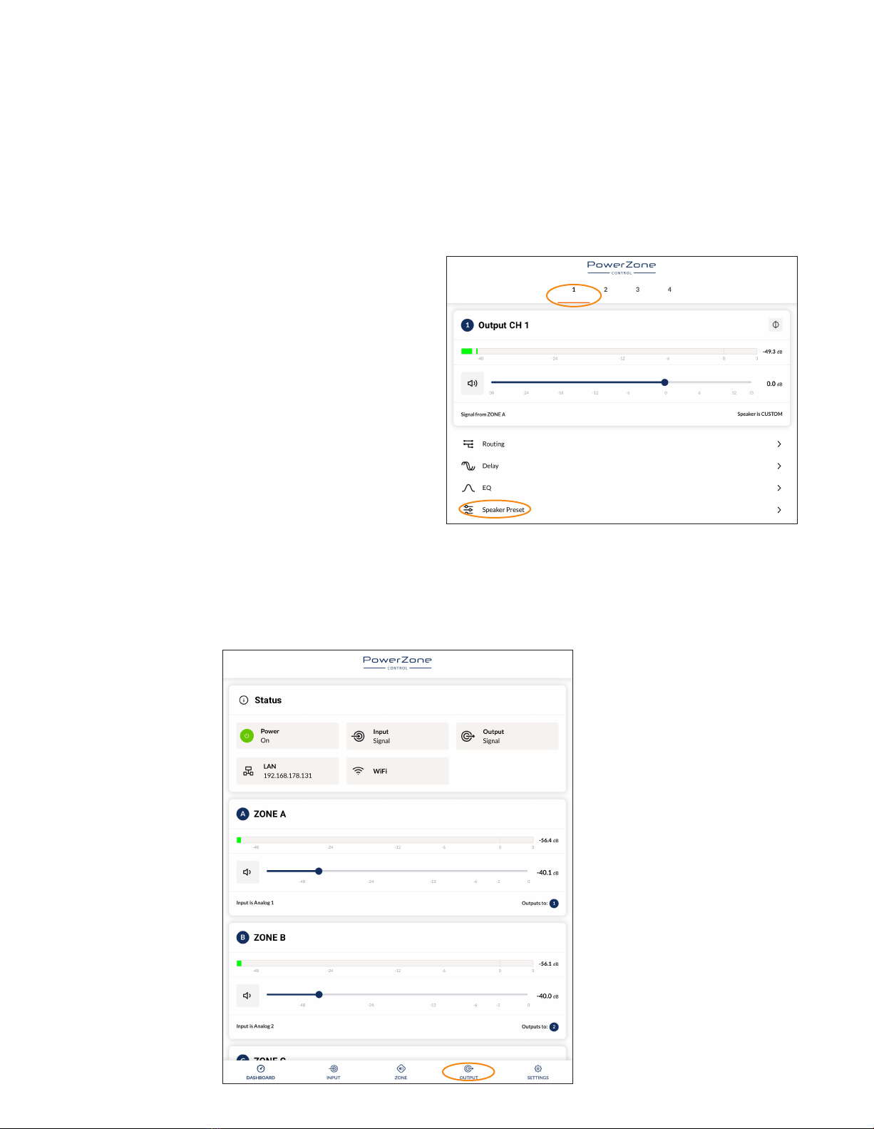
Step 2. On the computer
or mobile device,
navigate to the
PowerZone
Connect 3004
amplier web
interface and select
the Output tab.
Step 3. From the Output page select the required Output tab at
the top of the display and then select the Speaker Preset
menu opon.
NOTE: The exact appearance and layout
of the amplier web interface may vary
slightly depending on the device and
browser in use.

3. Connecon and Amplicaon
Step 4. Selecng IMPORT PRESET FROM FILE will open the
Speaker Preset Import pop-up box that provides the
opon to choose a preset le.
Step 5. Browse the download device for the les downloaded in
Step 1 and select the le named:
CBL523-PAS_PreSet_Locked_V1.2.zcp
Select IMPORT.
Step 6. The speaker preset le will now be applied to amplier
Output 1.
Step 7. With the appropriate speaker preset le (CBL523-PAS_
PreSet_Locked_V1.2.zcp) applied to amplier Output 1,
repeat Step 2 to Step 6 for any other amplier outputs
with CBL523-PAS speakers connected.
NOTE: Amplier outputs are selected from the numbered tabs at the
top of the amplier interface Output page.
IMPORTANT: It is vital for the
correct operaon of the CBL523-PAS
loudspeaker that the correct speaker
preset le is applied to the amplier
output.

4. Technical Informaon
4.1 CBL523-PAS Specicaons
4.1.1 System Performance
Frequency Response (-3dB) 71Hz - 18kHz
Frequency Response (-10dB) 55Hz - 18kHz
Recommended High-Pass Filter 48Hz
Horizontal Nominal Dispersion (-6dB) 160°
Vercal Nominal Dispersion (-6dB) 15°
Crossover Frequency 520Hz
Long Term Power Handling (Full Range) 160W
Impedance 4 Ω
Pressure Sensivity @ 1W/1m (2.83v) 91dB
Max SPL @ 1m 119dB
4.1.2 Physical Characteriscs
Enclosure Material 12mm birch plywood, engineered plascs.
Finish Two-part spray catalyzed Polyurea coang on
plywood.
Grille Material 16-gauge (1.6mm) perforated steel, powder-
coated nish, black.
Environmental Indoor use only.
Connectors/Bi-Amp Two (2) parallel-wired NL4 Neutrik® Speakon®
connectors.
Suspension/Mounng Wall/Ceiling Mount and Suspension Opons.
Hardware sold separately.
Dimensions (HxWxD) 8.08” x 13.78” x 8.9” (205.3 x 350 x 226.2 mm)
Net Weight 15lbs / 6.8kg
Shipping Weight 18lbs / 8.16kg

Rev D 22/08/2023
Designed in USA/Denmark - Made in USA.
Blaze, 1904 Fairfax Road, Suite B, Greensboro, NC 27407, US. [email protected]. www.blaze-audio.com
4.2 CBL523-PAS Mechanical Drawings
4. Technical Informaon
4.2.1 CBL523-PAS Loudspeaker Dimensions
8.08”
205.3 mm
8.9”
226.2 mm
13.78”
350 mm
Table of contents
Other Blaze Speakers manuals


Popular Speakers manuals by other brands


UNI electronic
UNI electronic UCA 8240 user manual

d & b audiotechnik
d & b audiotechnik Ci45 manual

d & b audiotechnik
d & b audiotechnik XSL8 manual

Cambridge Sound Works
Cambridge Sound Works OontZ XL user manual

Silvercrest
Silvercrest HG00286A Operation and safety notes

MB QUART
MB QUART NK1-116B Quick start installation guide


