Blickman LSQ 600 series Owner's manual
Blickman Supply Company
280 Midland Avenue M-1 Saddle Brook NJ 07663
INSTALLATION
SETTING UP THE URN —Place the urn carefully in position on urn stand or counter. Faucets should be located over a drip trough or similar
receptacle. Then connect water supply, electric, gas or steam in accordance with the following suggestions:
WARNING: GAS URN —Do not install gas urn near a combustible wall or counter top without proper insulation.
WATER CONNECTIONS —Connect urn water inlet connection with matching size water supply pipe. Valve inlet is 1/2" i.p.s. pipe. Somewhere in
the water supply line before the urn, there should be a union and shut-off valve for easy connection or later change. If local plumbing code requires
a check valve and vacuum breaker before urn inlet, be sure plumber has this part installed. A reducing valve should be provided if water pressure
is over 45 P.S.I.
ELECTRIC CONNECTIONS —Be sure that your current characteristics (voltage, etc.) agree with data specified on metal plate attached to urn.
An experienced electrician should make the installation and he should check that the proper size power cable leads to your urn and that the
circuit is fused adequately. (Do notsupply power to a dry urn.)
GAS CONNECTIONS —Connect 1/2" gas supply. Burner is rated at22,000 BTU on twin LSQ urn and 15,000 BTU on single LSQ urn. (Do not
apply heat to a dry urn).
STEAM CONNECTIONS —On steam heated urns, it is also recommended that a valve be placed in the steam line before the steam line is
connected to the urn. Steam pressure at urn location (not at your steam boiler) should match the pressure for which the urn was built, as indicated
on tag attached to the urn. Excessive pressure can be reduced by installing a reducing valve. Too low a pressure may result in insufficient heating
and improper functioning of the thermostat. Steam lines must be blown out before installation to eliminate any accumulation of chips, dirt or white
lead that may clog system.
ADJUSTMENT OF THERMOSTATS —Normally the thermostats should not have to be adjusted after installation. However, if any adjustment is
required, see pages 5-7.
Rev. 1 (Id) 2/79 1LSQ
"600
SERIES"
COFFEE URN
INSTALLATION,
OPERATION,
MAINTENANCE
MANUAL
FOREWORD CONTENTS
INSTALLATION. ................................................................1
OPERATION..................................................................3-4
CLEANING........................................................................4
ADJUSTINGTHERMOSTATS .......................................5-7
Your Blickman LSQ"600" Series is one of the finest coffee
urns available in the world today. It has been thoroughly tested
and inspected at the factory under actual operating conditions
and was in perfect condition when shipped from the factory.
However, even the best of equipment will not function correctly
unless it is operated and maintained with proper care. FILTERSYSTEMS............................................................8
TROUBLESHOOTING. ...............................................9-14
The purpose of this manual is to help you keep your urn in
perfect operating condition. It should be studied carefully at
time of installation and kept for future reference. Proper care in
operation and maintenance will protect your investment and
assure a uniformly delicious brew. (Additional copies of this
book are available at
$1.00
each.)
If any problems arise which are not covered in this manual,
contact y
our Blickman dealer or service agency at once. In any
correspondence with the factory, always include the urn serial
number. It is stamped into the upper right-hand section of the
urn body and is also found on the electrical data plate on the
control box.
WARRANTY
2LSQ

OPERATING INSTRUCTIONS
for COMBINETTE and TWIN NON-PRESSURE URNS
DO NOT TURN ON ANY HEATING UNIT UNTIL WATER IS PUT INTO
URN IN ACCORDANCE WITH THESE INSTRUCTIONS
OPERATION OF HEATING UNITS
3LSQ
WARNING
STEAM
Units healed by steam have a steam inlet a
nd outlet. Always leave outlet valve open. A
trap is recommended. Control heal by opening or closing inlet valve according to the amount of heat
required
GAS Burner height must be set so that the burner flame just reaches bottom of coffee urn. The
flame should not spread. Flame along bottom of the urn should not be wavy, otherwise the burner
will operate inefficiently.
ELECTRIC . . . Electrically heated units normally furnished with thermostat pre-set at Factory —
No. 10 position is 210 and decreases according to position you leave thermostat set at.
CAUTIONS
a. If steam is used for heating, pressure
should be approximately 20-25 Ibs. Do
not use a different pressure unless your
urn was ordered for it
b. Never allow water level in boiler gauge
to go lower than 3inches from bottom
of gauge
c Be sure that water is fully boiling
before brewing coffee
d. To protect coffee flavor, wash out urn
with hot water after every batch is
made and clean liner, gauges and
faucets often
e. If hard water condition exists, place
recommended type of water conditioner
in cold water inlet line leading to urn
f. Do not install gas heated coffee urn on
wood counter —— must be metal.

1.
Startdailywithawellcleanedcoffeeurn.
BETWEEN BREWS -Aquickrinsebetweenbrewsisdesirable.
2.Keepwaterinjacketataheightof2"fromthetopofthewater
gaugeglass.Fillbyopeningwaterinletvalve.IMPORTANT:
Donotfillabovethismark. 1.Rinseliner.
3.TurnthermostattoNo.10position.(Ifyoururniselectrically
heated). 2.Drainthewateroff.Theurnisreadyforthenextbrew.
OPERATION
CLEANING
4.Whileurnisheatingtobrewingtemperature:
A.Rinselinerwithcleanwater.
DAILY-Daily cleaningafterthelast batch ofcoffee is used
shouldberegularroutine.
1.
Afterallbrewedcoffeehasbeendrawnfromtheurnpourover
twogallonsof fresh hot waterand thoroughly brush itout with
longhandledbrush.
B.Fillfilter*withproperamountoffreshcoffee.Beexact...
don'tguess.Thequantityofgroundcoffeedependsonthe
desiredstrength —from 2 to 3 gallonsperpound.
Increasedamountsarerequiredforicedcoffeeordemi-
tasse.
2.
Drainthewateroff
,againpourover
2
gallonsoffreshhot
water,brush it out anddrain again. Wipe downliner with
cleantowel.
5.Five minutes after brewingis completed, removefilter and
discardold coffee grounds.NOTE: Never leave coffee
groundsinthelinerafterthistime.
3.Ifurnisnotgoingtobeusedagainimmediately, put a gallon
orsooffreshwaterintheliner.Donotdrainthiswateroff
untiljustbeforemakingnextcoffeebrew.
6.Afterremovinggrounds,takeagallonmeasurerandpour
brewedcoffeeovertoblendthecoffee. TWICE A WEEK -Coffeeurns must havea special scouring
twiceaweek.Toscourtheurnthoroughly:
1.Besurewaterjacketis3/4 fullofwaterandturnonheat.7.Allow10
minutesfor freshcoffeetoripen.Coffeeis nowready
toserve.
2.
Filllinerwithseveralgallonsofwaterandaddatleast1
-
1
/2
ozs.of coffee urn cleaningcompound. Allow thissolution to
remaininthelinerapproximately30 minutes, during which
timeheatshouldbeonfull.
3.
Scrubinsid
eof liner and insideof cover withlong handled
brush.
NOTE: Never serve coffeethat has been held over 1-1/2 hours.
Don'tmakefresh coffee on topof old. Always washout urn
beforeeachoperation.Don'tleavecoffeeinurnsovernight.
Washoutthoroughlybeforeclosing.Leaveagallonorsoof
freshwaterinliner. 4.Uselong thin brushtoclean coffee gauge glass.Use same
brushtocleanfittingatbottomoflinerandpipeconnectingto
coffeefaucet.
*Forcompletedetailsonuseandcareof
the BlickmanFilteringSystems,seepage8. 5.Drainurncleaningsolutionoffandrinse3 or 4
timeswithfresh
hotwater,repeatingsteps3 and 4again.Drainrinsewater.
6.Occasionallytakefaucetvalvesapartandcleanthoroughly.
7.Leaveagallonorsooffreshwater in urn until just before
brewingnextbatchofcoffee.
4LSQ
HOW TO ADJUST THERMOSTAT
(For electrically heated urns)
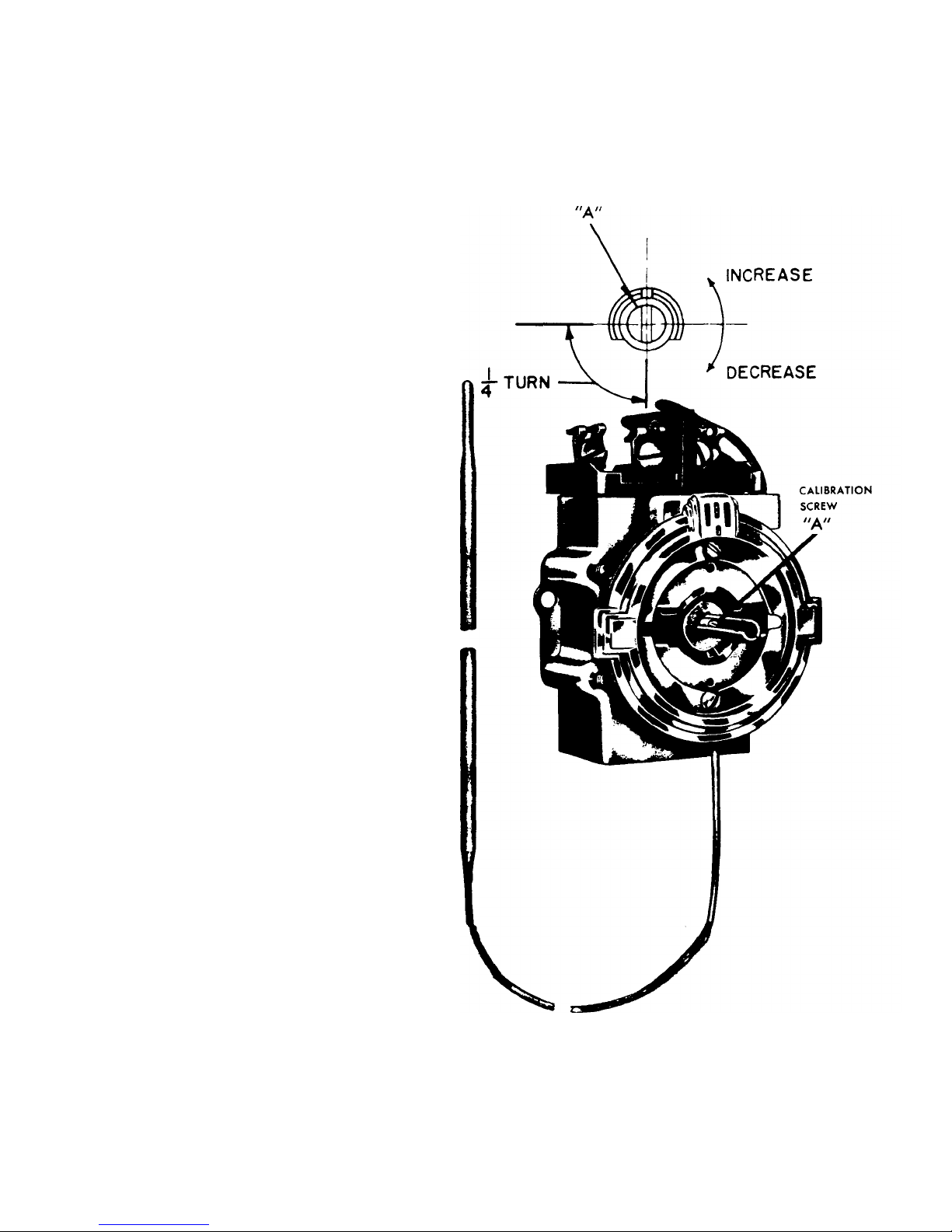
THERMOSTAT CALIBRATION
Your thermostat should be calibrated if it cycles off
before the urn reaches the brewing range on the dial
thermometer (200° -205°F) or if the urn reaches a
boiling point.
To Calibrate Thermostat:
1. Turn control to off position and remove black knob.
2. With a small screwdriver, turn screw "A" clockwise
to decrease and counter-clockwise to increase the
temperature.
3. Adjusting the calibration screw 1/4 turn will increase
or decrease the temperature approximately 10°F.
4. Replace knob and turn thermostat back to the No.
10 position and check to see if it is calibrated
properly. When the thermostat is in the No. 10
position —dial thermometer should stay in the
brewing range.
5LSQ
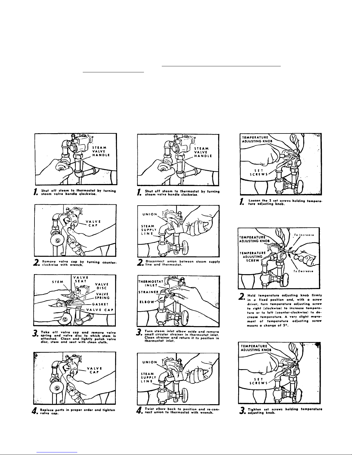
Instructionsfor Maintenance and Adjustment of Steam Thermostat
Steam thermostats are designed for use with steam pressure specified on
order for each urn. If cleaned regularly, the thermostat will operate properly
and give
many years of reliable service. Cleaning is important to satisfactory
operation. Therefore, follow these instructions carefully.
IMPORTANT: Before installation, blow out pipe lines and check strainer on inlet side of
thermostat lo make sure it is clean. Clean valve disc a lew days after initial installation (see
instructions in first column). Also, clean valve disc promptly whenever thermostatic action
appears defective.
CLEAN VALVE DISC AND SEAT
EVERY 60 DAYS
After several hours use on a new installation
and every 60 days thereafter, Valve disc,
gland pin and seat should be cleaned to insure
proper operation. Proceedas follows:
TO CHECK & CLEAN
STRAINER
If there is a noticeable increase in time
required to heat urn, this may be due to
clogging of the strainer on the inlet side of-
the thermostat by scale and other foreign
matter. The strainer should be cleaned to
restore normal flow of steam as follows:
(Note: Not all thermostats have strainer.)
TO ADJUST THERMOSTAT
Temperature adjustment of this thermostathas
been carefully checked at the factory and will
rarely require re-setting and adjustment.
Adjustment may be made if necessary as
follows:
6LSQ

THERMO-MAGNETIC AUTOMATIC PILOT
A tubular thermocouple of a small rod welded within a tube of heat resistant metal (A) bathed by the pilot flame generates an electric current.
Carried through heavy tubular copper conductor (B), the current energizes a heavy electro-magnet (2) capable of holding the valve mechanism
(5) in the operating position as long as the pilot flame remains lighted. Within a minute after pilot flame failure (perhaps caused by a draft,
clogging or "no gas") the electro-magnet releases with a positive snap action shutting off the main burner and pilot gas supply. THERMOSTAT
WITH AUTO SAFETY PILOT IS AN OPTIONAL FEATURE
PROCEDURE FOR LIGHTING OR RELIGHTING:
1. Turn GAS COCK HANDLE to "off" position and DIAL ASSEMBLY to lowest temperature position.
2. Wait sufficient length of time to allow gas which may have accumulated in burner compartment to escape.
3. Turn GAS COCK HANDLE to "Pilot" position.
4. Fully depress SET BUTTON, and light pilot burner. (Adjust, if necessary, as noted under "Pilot Burner Adjustment".)
5. Allow pilot to burn approximately 1/2 minute before releasing SET BUTTON. If pilot does not remain ignited, repeat operation allowing longer
period before releasing SET BUTTON.
6. Turn GAS COCK HANDLE to "on" position and turn DIAL ASSEMBLY to desired position. The main burner will then ignite.
PILOT BURNER ADJUSTMENT:
1. Remove pilot adjustment cap. Adjust pilot key, allowing flame to completely envelop the end 3/8" of the Thermocouple.
2. Adjust pilot burner air shutter (ifprovided) to obtain a soft blue flame.
MAIN BURNER ADJUSTMENT (Gas Input):
1. To adjust main burner flame, turn screw under GAS COCK HANDLE in either direction to regulate flow of gas to main burner.
To Recalibrate Thermostat:
a. Allow heater to set without the burner on for at least30 minutes to allow the water temperature within the tank to reach its equilibrium point.
b. Turn the DIAL ASSEMBLY until the main burner ignites.
c. Slowly turn the DIAL ASSEMBLY until the main burner is extinguished.
d. Place a Thermometer in the hot water flowing from the nearest faucet
e. If the DIAL ASSEMBLY setting is within 10° of the water temperature, recalibration is not necessary.
f. If the temperature variation is greater than 10°, recalibration may be effected by adherence to the following steps;
g. Remove DIAL ASSEMBLY GAS COCK HANDLE and ORNAMENTAL COVER, (to remove Ornamental Cover, unsnap at base, lift out and up),
and loosen (do not remove) screw. Hold STOP while screw is loosened, taking care not to move TEMPERATURE ADJUSTING SCREW.
h. Hold TEMPERATURE ADJUSTING SCREW and turn STOP until water temperature setting coordinates with that of the thermometer. i. Hold
TEMPERATURE ADJUSTING SCREW and STOP and tighten screw. j. Replace ORNAMENTAL COVER, GAS COCK HANDLE,DIAL
ASSEMBLY.
Thermocouple Connection
Poor contact between the Thermocouple Lead and the Magnet Assembly may cause the Valve to be inoperative even when the pilot is in proper
adjustment and position; if so, the contact points should be cleaned and tightened. This is accomplished by removing the Thermocouple and care
fully cleaning the parts that make contact with the Magnet Assembly.
CAUTION: When reassembling and tightening the Thermocouple Nut, only a small (3 or 4inch) wrench is necessary. Run nut down as far as
possible with the fingers. Set lock washer by making an additional 1/4 to 1/2 turn with wrench. 7LSQ
GENERAL -Making coffee with any of the Blickman filter systems is as simple as it is quick. First, carefully follow the
operating instructions on pg. 3-4, then pick up the specific directions below which apply to your filter.
TRI-SAVER SYSTEM
LOADING FILTER -Be sure your filter is thoroughly clean before using. Spread the coffee grounds evenly
in the bottom of the filter. (No filter paper is required.) Lock spreader plate in place on filter.
CARE OF FILTER -The Tri-Saver filter is durably constructed and will give you long, uninterrupted
service with reasonable care. Avoid striking or hitting your Tri-Saver against the receptacle that is used for
emptying the grounds. Flush out the old coffee grounds with hot water.
CLEANING FILTER -Clean your Tri-Saver thoroughly with hot water after each brewing operation. At the
end of the day, or at frequent intervals, fill a sink half full of hot water containing approximately one
teaspoonful of any good free-rinsing detergent per gallon and submerge the filter. Push the filter in an
upward and downward motion, so that the water will flow through the filter plates, cleaning them
thoroughly. Daily care will keep your filter clean and will assure perfect coffee flavor.
IF, FOR ANY REASON, YOUR TRI-SAVER FILTER DOES NOT GIVE YOU VERY
SATISFACTORY RESULTS, COMMUNICATE WITH US OR YOUR DEALER
PROMPTLY. YOU WILL RECEIVE PROMPT SERVICE AND FURTHER
INSTRUCTIONS SHOULD ANY BE REQUIRED.
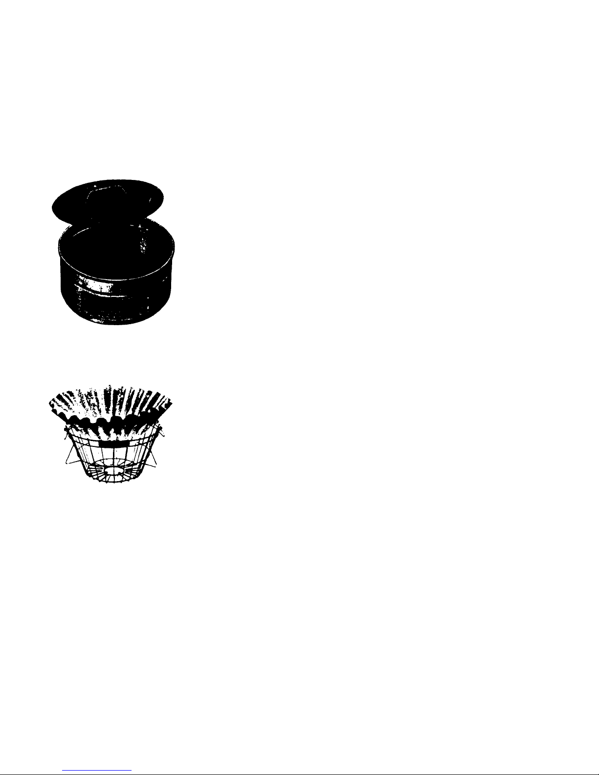
BREW 'N TOSS FILTER PAPER
FILTER PAPER -Be certain you have the correctsize paper for your Brew 'n Toss paper holder.
LOADING FILTER -Swing three wire handles up and out of the wire basket. Set a single sheet of filter paper into
basket and swing back the three handles to hold the paper firmly in place. Spread coffee evenly over bottom of filter
paper and set filter in top of urn.
CLEANING FILTER -Remove basket, dump filter paper and grounds into waste receptacle and rinse wire basket.
NOTE: Cloth bag may also be used in brew 'n toss basket. Urn
furnished standard with bale-type ring with cloth bag.
8LSQ
FILTER
SYSTEMS

TROUBLE CAUSE REMEDY
A LEAKS
NOTEREGARDINGLEAKS:Leakmaynotbeatlocation
wheredripfirstappearsasdripmaybeduetocondensation.
Wipeleakdry,thenuseurnandobservewhetherleak
reappearsanditsexactlocation.
A-1Leakaroundstemof
waterinletvalve. A-1Packingaroundvalvestemnot
tightornolongerservice-able. A-1Tightenpackingnut.Ifleakstilloccurs,removepacking
nutandreplacepacking.
TROUBLE SHOOTING
A-2
Leak around gauge glass. A-2
Gauge glass packing not tight or no longer
serviceable. A-2
Tighten upper & lower gauge glass packing nut depending on where leak
occurs. If leak continues, replace gauge glass washers.
Unscrew upper fittings.
Remove old washers and slip new ones in at each end. Replace glass
and tighten nuts.
A-3
Faucet Drips. A-3
Tomlinson inserts are worn and must be
replaced. A-3
Disassemble faucet and replace insert.
A-4
Fittings leak at body of urn. A-4. 1
Jam nut is loose. A-4. 1
Tighten jam nut. If this does not stop leak, proceed as outlined in the next
step A-4. 2
A-4. 2
Threads not adequately sealed. A-4. 2
Remove fitting. Clean threads in urn and on fitting. Apply fresh sealer and
reassemble fitting to urn making sure jam nut is firmly tight.
A-5
Leak at point where electric
heating element plug screws
into body. A-5
Threads not adequately sealed. A-5
See remedy A-4. 2above.
9LSQ

TROUBLE SHOOTING (Cont'd.)
TROUBLE CAUSE REMEDY
A-6
Leaks in urn body other than
at fittings. A-6
Pin holes or cracking of metal
due to insulation action of lime
or other abuse of urn.
A-6
Body leaks are best repaired at the factory. If soldering is attempted
in the field, metal must be thoroughly cleaned. Use only a flux made
specially for stainless steel and then neutralize completely. DO NOT
WELD OR BRAZE! ! !
A-7
Water leaks or sprays out
through top of urn. A-7.1
Water compartment overfilled through
oversight or because of leaky water
inlet valve.
A-7.1
Draw off excess water from water compartmentby openinghot
water faucet. Never fill to a level higher than uppermost mark on
water gauge glass. Water expands with heat and can cause an
overfilled condition. To check whether overflowing is due to leaking
water inlet valve, proceed as follows: Shut off heating unit to urn.
(Check cannot be made accurately if water is boiling.) Close water
inlet valve firmly and note accurately water level in gaugeglass. If
water level rises after a period of time, a leaky water inlet valve is
indicated. Remove valve bonnet, unscrew stem and install new
valve disc.
A-7.2
Excessive heat is applied to urn. This
is a rare cause, and is usually due to
excessive steampressure insteam
heated urns, or an improperly
adjusted electric thermostat in
electrically heated urns.
A-7.2
If steam pressure is considerably in excess of that for
which urn was ordered, install reducing valve to cut
pressure down to that recommended for urn. Or, control
heat, input by fuel control valve. On electric urns, adjust
thermostat as shown on page 5.
B FILTERING AND BREWING
B-1
Filtering through Tri-Saver
is slow. B-1. 1
Too fine grind prevents normal filtration. B-1. 1
Have coffee supplier match sample grind packed with Tri-Saver
filter. If sample is lost, write factory for another.
B-1. 2
Filter clogged because not cleaned
regularly and according to instructions.
Extenders in coffee may also cause
clogging.
B-1. 2
Follow instructions on plate attached to Tri-Saver filter, or see page
8. Clogged filter can be cleaned by soaking overnight or several
nights in water with a good detergent. Avoid using coffees with
extenders as it may not be possible to dean these out.
10 LSQ
B-1. 3
Soft water used. B-1. 3
Water may be "conditioned" but not softened. Slows up leeching
and destroys coffee taste.

TROUBLE SHOOTING (Cont'd.)
TROUBLE CAUSE REMEDY
B-2
Coffee too strong. B-2
Insufficient amount of water used to
brew batch or too much coffee used. B-2
Use proper proportion of water to coffee. If Tri-Saver filters are used, you
generally find it practical to use more water than with other methods to
obtain a given strength. Experiment will show best proportion of water to
coffee to suit your patrons' tastes.
B-3
Coffee muddy, fines in brew. B-3
Too many fines in coffee grounds. Also
water may not be hot enough. Or re-
pouring through coffee grounds.
B-3
Have supplier furnish coffee with as little fines as possible as these are,
difficult to filter out. Always use water at proper temperature when
brewing. Avoid repouring through coffee grounds. Follow operating
instructions.
B-4
Coffee too weak. B-4. 1
Grind too coarse, all flavoring matter not
extracted. B-4. 1
Use the correct grind for your method of filtering. For Tri-Saver filters,
have your supplier match grind sample furnished with urn.
B-4. 2
Tri-Saver filter is damaged, permitting
water to pass through through too quickly
for full flavor extraction.
B-4. 2
Examine filter for dents or damage due to abuse. If damaged, return to
factory for repair.
B-4. 3
Incorrect proportion of water to coffee. B-4. 3
See B-2 above.
B-4. 4
Water not at proper temperature. B-4. 4
Do not brew coffee unless water is at proper brewing temperature.
C HEATING SYSTEM, STEAM URNS
C-1
Urn does not heat up, or
heats very slowly. C-1. 1
Steam not reaching urn because inlet or
outlet valve is shut. C-1. 1
Be sure both steam inlet and outlet valves are open.
C-1. 1a
Check 115 Volt Electric Power
C-1. 2
Strainers and/or Steam trap in steam line
may be clogged. C-1. 2
Check and clean strainersand/or trap in steam line.
C-1. 3 Steam pressure at urn is too low. C-1. 3
First, check pressure at urn location to be sure it corresponds to
that for which urn was ordered. If pressure is low, increase boiler
pressure so that urn will receive sufficient heat for proper
operation. If this cannot be done. urn may have to be returned to
factory to have larger steam coils installed.
11
LSQ

TROUBLE SHOOTING (Cont'd.)
TROUBLE CAUSE REMEDY
C-1. 4
Lime deposits on interior insulate heating
coils and prevent heat from being
transferred to water.
C-1. 4
Clean out urn. Hard lime deposits may require factory cleaning. Install
water conditioner to prevent lime deposits.
C-1. 5
Thermostats may be cutting off steam
supply before boiling point is reached. C-1. 5
Adjust thermostats as per instructions on page 6.
C-1. 6
Solenoid on steam line not
opening. C-1. 6
Check and see if solenoid coil is energized. If coil is energized, pin
inside solenoid is stuck in closed position. Disassemble solenoid and
clean pin and seat. (A rebuilding kit containing a new pin diaphragm is
available from the factory or authorized service company.)
D HEATING SYSTEM, ELECTRIC URNS NOTE: Before making any adjustments to thermostat, shut off power.
After adjustments have been made. turn on power.
D-1
Urn does not heat up or heats
very slowly. D-1. 1
Power may be off. D-11
Make sure power switch &thermostat is turned on. If this does not
work, check to make sure that power line to urn has not been turned
off at some other point in the building or that fuse in line is not blown.
D-1. 2
Thermostat may be out of adjustment. D-1. 2
To check this and adjust thermostat, see instructions on page 5.
D-1. 3
Lime deposits insulate heating elements
preventing heat from being transferred to
water.
D-1. 3
Clean out urn. Hard lime deposits may require factory cleaning. Install
water conditioner to prevent lime deposit.
12LSQ
D-1. 4
Heating elements are burned out
because urn has been operated without
water or with insufficient water. Elements
may be burned out also because of
heavy lime deposits, or becauseof
natural service life limitations.
D-1. 4
Electrician can check with instruments to determine whether elements
are burned out. If the/are, shut off power to urn. Drain water from
jacket. Remove coffee liner nearest control box to provide access to
inner tank and heating elements. Disconnect cables attached to
heating elements. Caution: Thermostat, capillary tube and bulb
clamped must be undamped by pulling them off. Do not cut capillary
tube. Allow capillary tube and bulb to remain within urn. Unscrew
plugs on which heating elements are mounted and replace with new
heating element assembly ordered from factory. To prevent heating
element burn outs, never operate urn without water. Do not permit
water to boil out.

TROUBLE SHOOTING (Cont'd.)
TROUBLE CAUSE REMEDY
D-1. 5
Thermostat may be defective if it can not
be adjusted as suggested under D-1. 2
above.
D-1. 5
Shut off power, remove thermostat and replace.
E MISCELLANEOUS
E-1
Loud rumbling noises when
water is boiling. E-1
Lime scale due to hard water or foreign
matter in water supply is agitated by
boiling resulting in continual impact
against urn walls.
E-1
Shut off heat. Drain water from urn and clean out interior of urn by
removing liner. If trouble is due to lime, install water conditioner. If
due to considerable amount of foreign particles in water supply,
check "Y" strainer in supply line.
E-2
Water compartment overfills,
or water level rises when not
desired.
E-2.1
Water inlet valve left open. E-2.1
Be sure water inlet valve is closed when not refilling.
E-2.2
Water inlet valve does not shut off flow of
water completely because of faulty
washer.
E-2.2
Shut off main water valve in line immediately before urn. Remove
valve bonnet, unscrew valve stem and replace valve disc.
E-3
Water in urn jacket gauge is
discolored with coffee. E-3.1
Urn liner has been overfilled allowing
some coffee to seep into urn jacket. E-3.1
Drain jacket water and replace with fresh water. Avoid overfilling liner.
E-3.2
Leak at urn liner fitting allows coffee to
seep into water jacket. E-3.2
To check whether leak exists at urn liner fitting, drain off all liquid from
liner through coffee faucet. Dry liner thoroughly. Fill urn jacket with
water and allow to stand for about an hour. If there is a leak between
the liner and the jacket at liner fitting, water will appear in the liner. To
correct, install new liner.
E-4
Gauge does not register. E-4
Air is trapped in gauge tube because of
clogged vent at top of gauge. Liquid
cannot enter tube to proper indicating
level.
E-4
For all coffee gauges and water gauges, make sure vent hole
at top of gauge is not clogged.
13
LSQ

TROUBLE SHOOTING (Cont'd.)
TROUBLE CAUSE REMEDY
F HEATING SYSTEM, GAS URNS
F-1
Gasdoesnotcomeon. F-1.1
Openburnergascocks. F-1.1
Gascockstoburnersclosed.
F-1.2
Safetypilotout. F-1.2
Relightsafetypilot.
F-1.3
Thermostatmaybeoutofadjustment.
F-1.3
Tocheckthisandadjustthermostat,seeinstructionsonpage7.
F-2
Gasdoesnotshutoff. F-2.1
Manualby-passgascockisopen. F-2.1
Closethisgascock. Thisgascockshouldonlybe openedinthe
eventofapowerfailure.You may then usethis to feedgas to
theburnersmanuallyuntilpowerisrestored.
F-2.2
Thermostatissettoohigh. F.2.2
Tocheckthisandadjustthermostat,seeinstructionsonpage7.
F-3
Gasflamefloating. F-3.1
Gasorificeandairmixerplate
improperlyadjusted. F-3.1
Adjustorificeand airmixerplateorcontactlocal gascompany
toadjust.

PARTS
HOW TO ORDER
When ordering replacement parts for your equipment,
it is important that you give your dealer or us the
SERIAL NUMBER of your urn and, if possible, the
date of purchase. Also give catalog number and size
of urn. The serial number will be found stamped in the
upper part of the urn body at the right side as you face
the urn or on data plate of electric urns.
A minimum charge of $15.00 will be made on all
orders for spare parts when placed through factory.
Blickman
Equipment Corporation
2017 KERRIGAN AVENUE. UNION CITY, N.J.07087 (201) 867-8100
15LSQ

JANUARY,
1998
LSQ PART#
ID.# DESCRIPTION
LSQ-101 61900 THERMOSTAT. D-18
LSQ-104 60420 CONTACTOR.50 AMP/240V
LSQ-107 HEATER, 2500W-230V,
LSQ-107A 60725 HEATER,2500W-230V, SPECIAL BEND
LSQ-108 60770 HEATER, 3000W-230V
LSQ-108A 60771 HEATER,3000W-230V, SPECIAL BEND
LSQ-109 60760 HEATER, 3750W-230V
LSQ-109A 60761 HEATER,3750W-230V. SPECIAL BEND
LSQ-110 20330 BASKET, BREW N TOSS, 3 GAL, AT/CR
LSQ-111 20340 BASKET. BREW N TOSS, 6 GALLON
LSQ-112 20320 BASKET, BREW N TOSS, 10 GALLON
LSQ-113 22320 FILTER PAPER,3 GAL,#303,AT/CR, 500/CSE
LSQ-114 22330 FILTER PAPER.6 GAL.#604,AT/CR/MB, 500/CS
LSQ-115 22340 FILTER PAPER. 10GAL,#705,AT/CR/MB, 500/CS
LSQ-116 25520 URN BAGS, 3 GALLON (DZ)
LSQ-120 22660 GAUGE SHEILD CAP, LARGE HOLE, THREADED
LSQ-121 22845 GAUGE SHIELD LOWER FERRULE
LSQ-122 22770 GAUGE SHIELD ASSM.10-W/CAP & FER
LSQ-123 22810 GAUGE SHIELD ASSM, 16"W/CAP & FER
LSQ-124 22830 GAUGE SHIELD ASSM, 19"W/CAP & FER.
LSQ-125
GAUGE GLASS, 3 GAL,9-15/16"
LSQ-126
GAUGE GLASS. 6 GAL.15-15/16"
LSQ-127
GAUGE GLASS, 10 GAL.18-15/16", MINI-BREW
LSQ-128L 22910 GAUGE GLASS WASHERS, LOWER (DZ)
LSQ-128U 22900 GAUGE GLASS WASHERS. UPPER (DZ)
LSQ-129 22170 FAUCET.TYPE ES, TOMLINSON, (BLACK)
LSQ-131 22180 FAUCET. SEAT CUPS
LSQ-131A 22050 FAUCET. HANDLE. #13SLBE-1. BLACK
LSQ-131C 21995 FAUCET. BONNET, BLK PLASTIC
LSQ-131D 22075 FAUCET. SPRING
LSQ-131E 22140 FAUCET. STEM, NEW STYLE
LSQ-131G 22122 FAUCET, REPAIR KIT, BLACK. (ES)
LSQ-132 25160 DIAL THERMOMETER (BREW ZONE)
LSQ-136 23090 KNOB, COVER
LSQ-148 22840 GAUGE SHIELD HOLDER, BLACK PLASTIC
20430 20430 BRUSH.LINER
20440 20440 BRUSH. GAUGE GLASS
22575 22575 LEG INSERT, ADJUSTABLE. CHROME PLATED
61278 SOLENOID REPAIR KIT. REFILL, ASCO
PRICES ARE SUBJECT TO CHANGE WITHOUT NOTICE!
LSQ
SERIES
Table of contents


