Kees van der Westen Mirage Slim Jim User manual

[Typ hier] [Typ hier] [Typ hier]
Installation manual Slim Jim
espresso machines
(Original instructions)
Document ID: Sup-Tim-Eng Date of issue: December 20, 2018 Revision date: June 24, 2020

CONTENTS
Slim Jim Installation manual page 1
Designation............................................................................................................................................ 2
Safe operation........................................................................................................................................ 2
Installation manual................................................................................................................................ 3
Parts identification ............................................................................................................................... 3
Installation summary............................................................................................................................ 4
Check location................................................................................................................................. 4
Unpack............................................................................................................................................. 4
Install machine................................................................................................................................. 4
Transfer machine to owner/user...................................................................................................... 4
Water Quality....................................................................................................................................... 5
Water supply........................................................................................................................................ 6
Water treatment system ...................................................................................................................... 6
Waste/drain ......................................................................................................................................... 6
Machine location.................................................................................................................................. 6
Counter surface................................................................................................................................... 6
Pump location...................................................................................................................................... 6
Electric mains ...................................................................................................................................... 7
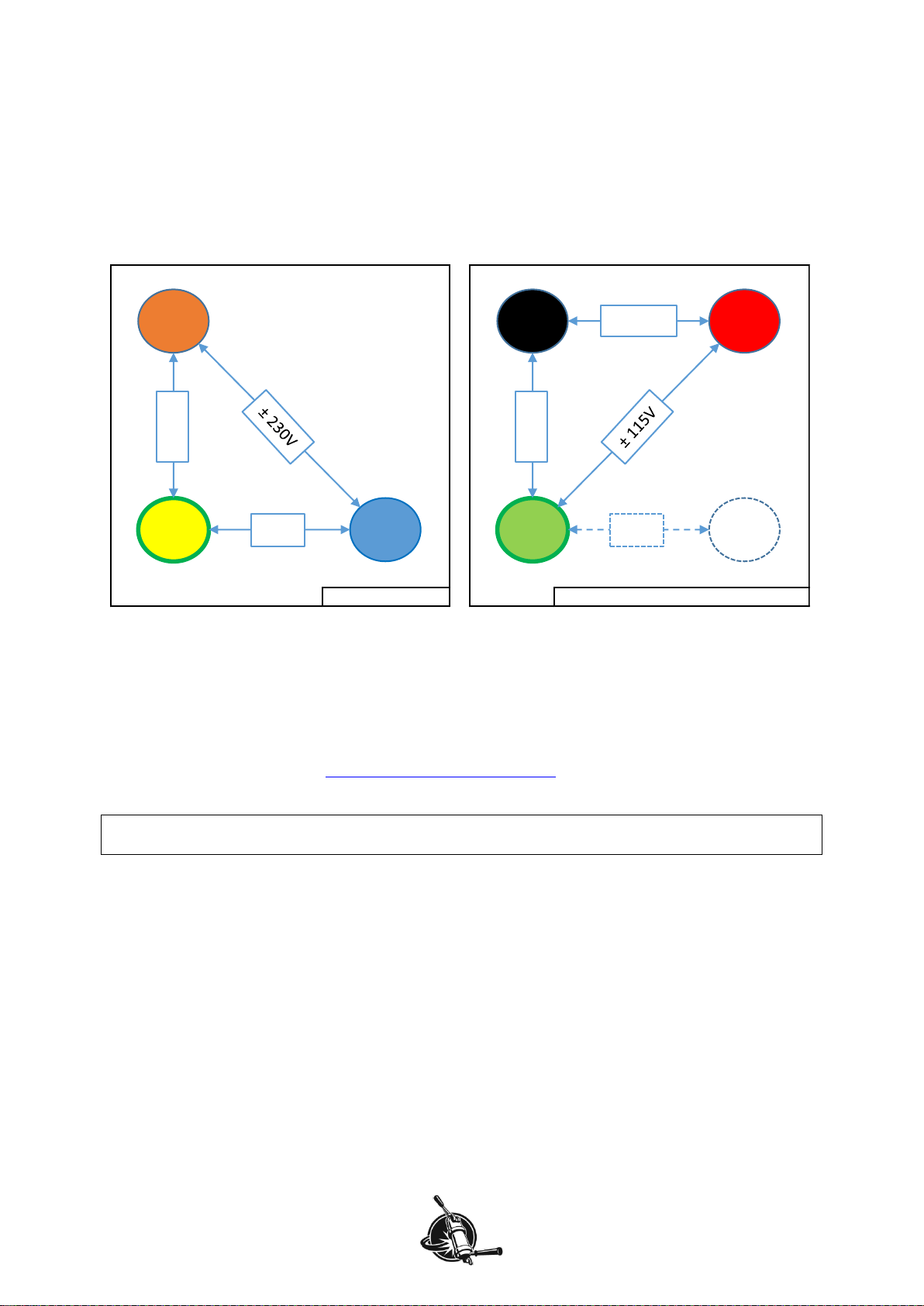
3-phase machine............................................................................................................................. 7
single-phase machine...................................................................................................................... 8
3-phase / single phase conversion.................................................................................................. 8
Unpack................................................................................................................................................. 9
Connect to water supply.................................................................................................................... 10
Connect to drain/waste...................................................................................................................... 11
Connect pump cable.......................................................................................................................... 11
Connect electric mains ...................................................................................................................... 12
First fill.................................................................................................................................................. 13
Heat up.................................................................................................................................................. 15
Adjust mix-water temperature............................................................................................................ 19
Hand over machine ............................................................................................................................. 21
Maintenance......................................................................................................................................... 23
Contact information ............................................................................................................................ 23

GENERAL
Slim Jim Installation manual page 2
Designation
This manual applies to the 2-group and 3-group Slim Jim Mirage espresso machines with touchpad or
Bastone operation manufactured by Kees van der Westen Espressonistic Works B.V. A separate
rotational pump with electric motor is part of the appliance.
Safe operation
•The espresso machine has to be placed in a horizontal position on a sturdy and flat surface.
•If the supply cord is damaged, it must be replaced by the manufacturer, its service agent or
similarly qualified persons in order to avoid a hazard.
•The new hose-sets supplied with the appliance are to be used. Old hose-sets should not be
reused.
•Intended use of the appliance is restricted to well-trained personnel only.
•The appliance must be installed in locations where it can be overseen by trained personnel.
•The appliance may not be left unattended when there is the possibility that children and/or
vulnerable people can reach the machine.
•This appliance can be used by children aged from 8 years and above and persons with reduced
physical, sensory or mental capabilities or lack of experience and knowledge if they have been
given supervision or instruction concerning use of the appliance in a safe way and understand the
hazards involved. Children shall not play with the appliance. Cleaning and user maintenance shall
not be made by children without supervision.
•The mains electricity the appliance is connected to must include a residual-current-circuit-breaker
of 30 mA.
•The appliance may not be cleaned with the aid of a water jet.
•The appliance is not suited for outdoor use.
•Ambient temperature for correct operation of the appliance is 10-30°C (50-86°F).
•If ambient temperature falls below 5°C (41°F), keep the machine at ECO or ON to prevent freezing
of water inside the machine.
Note that the external rotational pump should be kept above freezing point of water as well.
Whenever the machine and/or pump have suffered freezing conditions, ask a technician to start-
up the appliance again.
•It is advised to install a leak prevention system as the appliances is directly connected to the water
mains. An unattended leak can cause serious damage to the premises.

Slim Jim Installation manual page 3
Installation manual
Parts identification
Figure 1. Showing main operational parts of the Slim Jim Duette Bastone version with TECH legs. The
Slim Jim Triplette has three groups but its functions are identical to the Duette. On the Touchpad
version, the group brewing lever units are replaced with touchpads.
1. Right hand group 3-digit display (shot-timer and/or temperature)
2. Main switch (switches power to everything but the heating circuits)
3. Heat switches 1, 2 and 3 (switches power to steam boiler heating and group heating)
4. (Centre group 3-digit display; only on Triplette: shot-timer and/or temperature)
5. Capacitive interface and display of controller
6. Left hand group 3-digit display (shot-timer and/or temperature)
7. Volume toggle switch (left group)
8. Program & continuous button switch (left group)
9. Group indicator light (left group)
10. Group brewing lever (left group)
11. Group (left)
12. Two-stage pre-infusion cylinder
13. Hot water spout
14. Hot water toggle switch (hot water only)
15. Hot water button switch (mix water)
16. Coffee brew pressure gauge (right group)
17. Steam valve (right)
18. Steam wand (right)
A. Cup-rack (metal version, shown in crackle black)
B. Drip-tray
Not visible on this photo:
•Green indicator lights for heating spirals (one for each spiral; see page 15)
•Connection for external temperature probe (see page 15).
10
11
12
1
2
B
A
3
7
8
9
17
18
(4)
5
6
16
13
15
14

INSTALLATION MANUAL - summary
Slim Jim Installation manual page 4
Installation summary
Check location
1. Check water quality.
2. Check water supply.
3. Have an adequate water treatment system installed.
4. (Flush water treatment system.)
5. Check water waste/drain.
6. Check countertop.
7. Check cupboard for pump location.
8. Check electric mains.
Unpack
9. Lift top from crate.
10. Check accessories.
11. Check for transport damage.
12. Read installation manual.
13. Lift machine onto countertop.
Install machine
14. Connect machine to water supply and waste.
15. Open water tap.
16. Plug power cord onto pump motor.
17. 3P-N-E versus P-N-E electric mains.
18. Connect machine to electric mains.
19. Fill machine with water with heating circuits OFF.
20. Run cold machine, check for leaks.
21. Switch heating circuits ON.
22. (Install and adjust grinder).
23. Program service telephone number into controller.
24. Adjust TIME/DAY (and perhaps Celsius –Fahrenheit)
25. Check main functions of machine.
26. Brew first coffee, adjust pump-pressure.
27. Check/adjust hot water temperature.
28. Write machine number, installation date and other specifics in Service record.
Transfer machine to owner/user
29. Explain main features to new user(s) and manager.
30. Show User manual (on website).

INSTALLATION MANUAL –check location
Slim Jim Installation manual page 5
Water Quality
Have the local water tested and ask the water supply company if there can be seasonal changes in
water quality and when so, in what order these changes occur. Install a suitable treatment system that
at least includes a carbon block in order to not only traps drug-remnants, Chlorine and organic
compounds but also prevents rigid particles >30 μm to enter the pump.
Optimally, the water fed into the espresso machine would fall in the high end of the SCA “core zone”,
see Figure 2, and have a pH of 7.0-7.5 (at 25°C).
Figure 2. Alkalinity vs-Total Hardness graph showing the SCA “core zone” in green outline.
Besides the Alkalinity and Total Hardness requirements, the water should have the following
properties:
Parameter
Target
Acceptable range
unit
Total Hardness
72
50-175#
ppm
Total Alkalinity
40*#
40-75#
ppm
pH
7.0*
6.5-7.5*, 6.5-8.0#
--
Electrical conductivity
< 3 times Alkalinity
(in ppm) #
μS/cm1
Total Dissolved Solids
150*
75-250*
ppm1
Calcium Hardness
51-68*
17-85*
ppm
Sodium
10*
at or near 10*
ppm
Sulphate
30
0-50
ppm
Chloride
0
0-30
ppm
Silica
0
0-5
ppm
Odour and colour
clean*, fresh*, odour free*, clear*
Taste influencing organic compounds*#
not present
Chlorine#, Hypochlorite#, Chloramines#
Iron#, Lead#, Manganese
* SCAA Technical Standards Committee, 2009: water properties for optimum taste.
# Values from “The SCAE water Chart” (2015?).
Table 1. Showing parameter values for water meant to brew coffee with.
Water with properties that lie within the SCA “core zone” and correct pH combines technical aspects
enabling a safe operation and sensory aspects yielding a high-quality brew, provided the other
parameters are met as well. High brew-ratio’s, as for espresso, shift the optimum of total hardness and
alkalinity towards higher values within the core zone.
1
The conversion from electrical conductivity to TDS depends heavily on the water composition and temperature, yielding results
that can vary significantly. Additionally, even if the estimated TDS value is accurate, it does not contain any information about
what the TDS is actually made up of.
0
20
40
60
80
100
120
020 40 60 80 100 120
Total Hardness (ppm CaCO3)
Alkalinity (ppm CaCO3)
SCA
core
zone

INSTALLATION MANUAL –check location
Slim Jim Installation manual page 6
Water supply
Rated pressure: 0.1-0.5 MPa (1-5 bar)
Rated flow: minimum 4 litre/minute
The water supply should be able to deliver a minimum amount of 4 litres per minute in the range 0.1-
0.5 MPa (1-5 bar). The machine and accompanying rotary vane pump must be connected with the
supplied new set of high-pressure hoses (two hoses, each 1.5 meter long), old hose-sets should not
be re-used. The distance between water treatment system and pump and the distance between pump
and machine cannot be greater than 1.5 meter unless there is appropriate material available to
increase these distances.
Notes!
Not included in the shipment are supplies to make the connection between the water-tap and the
water treatment system.
National rules/regulations may apply when the appliance is connected to the water mains.
Water treatment system
The water treatment system should also be able to deliver a minimum amount of 4 litres per minute
and should at least have a carbon block that not only traps drug-remnants, Chlorine and organic
compounds but also prevents rigid particles >30 μm to enter the pump.
If the resulting water does not fall into the SCA “core-zone” (see Figure 2) have additional treatment
installed.
Notes!
Flush the water treatment system according to the manufacturers instruction before connecting it to
the pump-inlet.
Make sure that the functioning of the water treatment system will be checked on a regular basis.
Waste/drain
The appliance has two drain hoses: one for the drip tray and one for the machine itself. These semi-
flexible hoses have an external diameter of 20 mm (inner diameter: 16 mm). The hoses must slope
downwards all the way from machine to waste to prevent clogging. The waste at the location should
have a minimum inside diameter of 38 mm to accommodate for the two hoses and incorporate a
water-lock to prevent smelly odours.
Machine location
The machine is only to be installed in locations where it can be overseen by trained personnel.
Areas where a water-jet could be used are not suitable as location for the machine.
Counter surface
The countertop must be sturdy enough to easily support the machines’ weight (when filled: up to
100kg) plus extra equipment (one or two coffee-grinders, tableware, …). The surface should have a
height of 95-100 cm and be smooth, flat and horizontal.
It is advised to think about the location of holes in the countertop where the water and waste hoses
and electric cables should pass before the machine is installed.
Pump location
There should be nearby space for the electric motor with rotary vane pump. The pump-assembly
should not be able to touch the walls of the cabinet it is located in to prevent noise. Further noise
reduction can be achieved by placing the assembly on a 2-4cm thick rubber-foam sheet with
dimensions: 16x30cm (not supplied with machine). The pump will be electrically connected to the
espresso machine with an approximately 2 m long cable.
Areas where a water-jet could be used are not suitable as location for the pump-assembly.
Make sure there is air-flow possible near the motor to prevent overheating.

INSTALLATION MANUAL –check location
Slim Jim Installation manual page 7
Electric mains
Rated voltage: ~230V / 3N~400V, 50 / 60Hz
Rated power: max. 34.7 (230V) / 11.6 (400V) Amp per phase, see Table 2 for details.
Danger
If the supply cord or the pump connection cord is damaged it must be replaced by the manufacturer,
its service agent or similarly qualified persons in order to avoid a hazard.
The appliance is to be supplied through a residual current device (RCD) having a rated residual
operating current not exceeding 30mA.
Slim Jim
peak power
at 230 Vac
version
per
phase
Duette
Triplette
Duette
Triplette
4800W steam power
6000W steam power
kW
Amp
kW
Amp
kW
Amp
kW
Amp
3-phase
(3N~400V)
L1
2.1
8.9
2.1
8.9
2.5
10.7
2.5
10.7
L2
2.1
8.9
2.1
8.9
2.5
10.7
2.5
10.7
L3
2.2
9.7
2.3
11.6
2.6
11.4
3.1
13.4
(N)
2.2
9.7
2.3
11.6
2.6
11.4
3.1
13.4
single phase
(~230V)
L
L1
6.3
27.5
6.8
29.5
7.5
32.7
8.0
34.7
(N)
L2
6.3
27.5
6.8
29.5
7.5
32.7
8.0
34.7
Table 2. Showing peak power in the different phases for different machine versions.
The machines’ internal electrics consists of 3 heating circuits and an operation circuit. Each circuit is
meant to function on 230Vac. The range in which it can function safely is 208-240Vac. Electric mains
can be connected in two ways to the machine. Check if the electric mains of the location matches the
configuration of the machine.
3-phase machine
What we call a three-phase machine must be connected to 3P-N-E power (3 Phases + Neutral +
Earth, see Figure 3) with 120 degrees phase shift between phases. Such power is characterised by:
220-240Vac tension between each phase and neutral (or Earth) and 380-400Vac tension between the
phases. For peak power, see Table 2.
Figure 3. 3P-N-E electric mains. Peak current of the Slim Jim is 9.7 –13.4A per phase.
3N~400V; 3P-N-E
N
L2
L1
L3E
±400V
±0V

INSTALLATION MANUAL –check location
Slim Jim Installation manual page 8
single-phase machine
What we call a single-phase machine must be connected to P-N-E (single Phase + Neutral + Earth) or
2P-E (split Phase + Earth) power mains, see Figure 4. Note that the 2P-E configuration does NOT
make use of the neutral wire of the electric mains. For peak power, see Table 2. The tension between
the phase and neutral (P-N-E power) or the tension between the two phases (2P-E power) should be
220-240Vac.
Note that with single-phase peak current in the mains cable and the locations’ wiring is a lot higher
than with 3-phase power.
Figure 4. At left P-N-E, at right 2P-N-E. The machine can make use of L1 and L2 plus E (without N) of
the right electric mains configuration. Peak current is 27.5-34.7A.
3-phase / single phase conversion
The machine will be prepared in the factory for connection to either 3P-N-E or P-N-E/2P-E power and
will show respectively 3N~400V or ~230V on the identification tag.
Conversion is possible but requires replacement parts. Replacement parts and instruction for the
conversion can be obtained at: support@keesvanderwesten.com.
Note!
National rules/regulations may apply when the appliance is connected to the electric mains.
~230V; P-N-E
N
L
E
±230V
±0V
2N~230V; 2P-N-E, split-phase
N
L2L1
E
±115V
±0V
±230V

INSTALLATION MANUAL –unpack
Slim Jim Installation manual page 9
Unpack
1. Straighten the tabs that fixate the lid to the wooden crate, then remove the lid.
2. Unpack only the loose materials inside the crate.
3. remove the shelf from the crate.
4. Straighten the tabs on the two diagonally ribs of the crate.
5. Undo the screws that hold the sides of the crate to the bottom.
6. Remove the sides of the crate from the bottom.
7. Check if all accessories are present.
8. Remove packing material from machine.
9. Check the machine for transport damage.
10. Get adequate help to lift the machine from the bottom of the crate onto the countertop.

INSTALLATION MANUAL –install
Slim Jim Installation manual page 10
Connect to water supply
Rated pressure: 0.1-0.5 MPa (1-5 bar)
Rated flow: minimum 4 litre/minute
The machine is equipped with a non-return valve that prevents water flowing back to the pump. The
pump itself does not have a non-return valve.
Note!
When installing a new machine, always use new water supply hoses.
Do not re-use the hoses from a replaced machine.
•Connect water tap to the inlet of the water treatment system with a suitable hose (not included).
•Make sure the water treatment system has been flushed according to the manufacturers
specifications.
•Close water mains.
•Use one of the supplied high-pressure hoses to connect the outlet of the water treatment system
to the inlet of the pump. The connection on the hose is a 3/8”BSPP swivel-nut.
Note!
National rules/regulations may apply when the appliance is connected to the water mains.
•Mount the high-pressure hose that is connected to the machine onto the outlet of the pump.
•Open water mains.
As there now is water mains pressure onto the machine, the coffee boilers will start to fill while
compressing the air inside the coffee system.
Figure 5. Showing the water connections on the pump. Water mains will be attached to water
treatment system (not shown in the photo) and from there via the pump onto the espresso machine.
Note that the water treatment system and supply hose are NOT included in the shipment.
espresso
machine
water
treatment
system
in
out

INSTALLATION MANUAL –install
Slim Jim Installation manual page 11
Connect to drain/waste
•Normally, the drain hose of the machine will already be mounted onto the machine. The drain
hose of the drip-tray is not yet mounted.
oSlide a hose clamp over the separate drain hose.
oPush the end of that drain hose onto the pipe of the drip-tray and tighten the hose clamp.
•Lead the two drain hoses to the waste of the location (with water lock!). To prevent clogging
and/or pinching, make sure the hoses slope down all the way between the machine and the waste
and make sure the hoses do not make a sharp bend or are led over a sharp angle.
•The drain runs off best when the end of the hose is above water-level in the water lock.
Figure 6. The drain hoses should not slope up (left) or make a sharp bend (centre).
Connect pump cable
Danger
If the pump connection cord is damaged it must be replaced by the manufacturer, its service agent or
similarly qualified persons in order to avoid a hazard.
•Connect the female plug on the pump-cable to the male plug at the pump.
•Tighten the plugs with the latching ring (turn clockwise).
Figure 7. Plug the pump-cable onto the pump-motor and secure latching ring.
machine machine machine
waste
waste
waste
espresso
machine
pump motor
latching
ring

INSTALLATION MANUAL –install
Slim Jim Installation manual page 12
Connect electric mains
Rated voltage: ~230V / 3N~400V, 50 / 60Hz
Rated power: max. 32.2 (230V) / 11.3 (400V) Amp per phase, see Table 2 for details.
The appliance is to be supplied through a residual current device (RCD) having a rated residual
operating current not exceeding 30mA.
Normally the mains cable will not have a plug attached to it. This is to allow for a smaller hole in the
countertop to feed the cable through.
The machine can be equipped with 3 different mains cables, see Figure 8.
3-phase
European:
5x 2.5mm2
3x 7.8-11.3A
1-phase
European:
3x 6.0mm2
25.2-32.2A
1-phase
USA:
3x 10AWG
25.2-32.2A
Figure 8. The 3 different main cables the machine can be equipped with. Note that in the “alternative”
USA connection phase1 is described with -115Vac meaning in “counterphase to phase2”.
Danger
If the supply cord is damaged it must be replaced by the manufacturer, its service agent or similarly
qualified persons in order to avoid a hazard.
•It is advised to check an existing wall socket before mounting a plug on the mains cable.
•Disconnect electric power in the fuse box of the building if the machine is hooked straight into a
wall box.
•Check if all switches on the machine are in the OFF position (toggle-lever pointing down).
•Mount the cable directly into the wall connection box or mount the correct plug on the mains cable
and plug into existing wall socket.
•Re-connect electric power in the fuse box.
If a 16A CEE 3P-N-E plug is already mounted on a new three-phase machine it will be connected as
in Figure 9.
looking from right into
the 16A CEE plug shown
on left
Figure 9. 16A CEE 3P-N-E plug mounted on mains cable.
earth
neutral 0Vac
phase1 230Vac
phase2 230Vac
phase3 230Vac
earth
neutral 0Vac
phase 230Vac
earth earth
neutral 0Vac or: phase1 -115Vac
phase 230Vac phase2 115Vac
E
N
P1
P2
P3
E
P2
P1
P3
N

INSTALLATION MANUAL –install
Slim Jim Installation manual page 13
First fill
1. (Verify that all 3 HEAT switches are in the OFF position: lever pointing down.)
With the water-mains open and electric mains connected, turn the main switch ON (right hand side
switch, toggle-lever up). The display will show a start-up window with software-version information
and then turn to stand-by (“NO HEAT”).
NO HEAT
window
stand-by mode:
the boilers will not
heat up
☼
touch “NO HEAT”
2. Touch the centre button to turn the machine ON, the display will change to:
operational window
(Triplette)
temperature too low
but no heating
command
On the Duette operational window, the GROUP 3 “button” is not present. All separator bars are grey
indicating that controller is not sending out any signal to heat.
3. At this point the pump will be activated and the steam boiler will start to fill. As the coffee system
up to now has been filled at water mains pressure, this will continue to fill due to the increased
water pressure. Listen if you can hear water flowing into the steam boiler. If you do not hear water
flowing, there may be a blockage in the fill-system that has to be resolved before continuing.
4. The controller has a safety shut-down when the fill valve is open for longer than 2 minutes. The
steam boiler will not be completely filled yet after 2 minutes and the controller will thus shut down
and the LED(s) on the Bastone units or touchpads will start flashing.
5. Switch the main switch OFF (toggle-lever down) and wait for the displays to go blank, then turn
the main switch ON again, wait for the NO HEAT window, then touch the “NO HEAT” button: filling
will continue after a few seconds.
6. During this second filling, safety-level in the steam boiler will be reached and the display will
change (grey separator bars turn orange) to show that a heating command is given by the
controller. Since the heat switches are still in the OFF position, the boilers will not heat up yet.
NO HEAT
window
stand-by mode:
the boilers will not
heat up
☼
touch “NO HEAT”
operational window
showing boiler
temperatures and
heating command
On the Duette operational window, the GROUP 3 “button” is not present. Safety-level in steam boiler
is reached. Orange separator bars indicate that the controller is sending out signals to heat to all
boilers. Heating up will start when the HEAT switches are in the ON position (see next section).
7. Activate all groups (push-button on Bastone or upper button of touchpad) until water runs from the
group, then de-activate the groups.
8. If the steam boiler is not yet filled after these 2 “runs”, the LED(s) will start flashing again; repeat
the turning OFF-ON procedure.
9. When the OFF-ON procedure has to be repeated more than 2 times, it is possible that the steam
boiler does not fill (quickly enough) due to blockage in the system or very low pump-pressure
setting. Check before continuing.
10. When the filling has stopped without the LED(s) flashing the steam boiler is filled up to operational
level.
11. Re-check if water is flowing from all individual groups upon activation of the groups.
SUNDAY 08 : 00
TECH. ASSISTANCE
KEES VAN DER WESTEN
SLIM JIM
NO HEAT
GROUP 1
18.6
GROUP 2
18.7
GROUP 3
18.5
STEAM
18.6
MENU
SUNDAY 08 : 00
TECH. ASSISTANCE
KEES VAN DER WESTEN
SLIM JIM
NO HEAT
GROUP 1
18.6
GROUP 2
18.7
GROUP 3
18.5
STEAM
18.6
MENU

INSTALLATION MANUAL –install
Slim Jim Installation manual page 14
12. Mount a portafilter with blind-filter in one of the groups and activate that group. After the pre-
infusion cylinder is filled the pressure should increase rapidly to about 9 bar on that groups’
pressure gauge, if not, adjust the pump-pressure (see Figure 10).
Note that lowering the pump-pressure will not have an effect on the pressure gauge as there is a
check-valve in the coffee system. De-activate the group, lower the pump-pressure and then re-
activate the group to check. Remove the blind filter after this initial adjustment.
13. Press the mix-water button to see if water is flowing from the spout (this will be at very low flowrate
as there is no steam pressure and thus no hot water yet).
14. Check the machine for leaks.
Figure 10. How to adjust the pump-pressure. Undo the locking nut, then twist set-screw to correct the
pressure. Tighten the locking nut when done. Re-check brew-pressure after tightening the locking nut.
decrease pressure
increase pressure
set screw
locking nut

INSTALLATION MANUAL –install
Slim Jim Installation manual page 15
Heat up
1. Switch all three heat switches ON (lever up). This allows power to be fed onto the SSR’s in the
machine.
2. Check if all the green indicator lights underneath the electrics box are lighting up (see Figure 11).
a. If a single indicator light does not light up, it is possible that the corresponding overheat
safety switch has cut-out during transport:
Turn the machine OFF (MAIN switch and all 3 HEAT switches), remove the appropriate
body panel and press the central button of the overheat safety switch inward to re-set (see
Technical manual).
b. If corresponding indicator lights of a heat circuit (e.g. both most left lights of each set) do
not light up it is possible that the corresponding auto-fuse has cut power to that circuit.
Open the electrics-box (see Technical manual) to check the circuit breakers.
Figure 11. Indicator lights (and external sensor jack) underneath the electrics box. In a Duette the
most right indicator (3) is not present. The above situation (all indicators are lit) indicates that all
heating elements receive power.
3. Check heating up: When all indicator lights are lit (see Figure 11), the boilers will be heating up
(unless the heating element is not functioning) and the temperature readings on the displays will
increase. The steam boiler temperature will initially only rise very slowly as the sensor is located
above the water level.
operational window
at start coffee
boilers heat up
faster
4. Heating up from 20°C to operational temperature will take about 15 minutes, during this heat-up:
Check expansion pressure: Make sure that all groups are filled with water (activate all groups and
check if water flows from each group immediately). Mount a blind filter in the left group and
activate that group using the “continuous button”. Pressure will rise to pump pressure rather
quickly and then slowly rise to a maximum pressure: the expansion pressure. The cold water
heating up is expanding which leads to increasing pressure until the expansion valve starts to spill
drops of water into the drain. The expansion pressure should be in the range 11-13 bar (contrary
to other machines we made the expansion pressure cannot be adjusted on this machine).
5. This would be a good moment to set/adjust a few parameters in the “technician level” of the
controller:
On the touchpad: touch the “MENU” button, then the “SETTINGS” button, then the “TECHNIC
LEVEL” button. In the next window construct the technician password using the arrows (the
number 66666), then touch “ENTER”. In the next windows a service telephone number can be
stored, the level-probe sensitivity can be adjusted (low-medium-high, depending on water
conditions), the choice made between filling possible during brew or not, and the flow-meter type
adjusted (after changing flow-meters).
operational window
touch
MENU
☼
GROUP 1
45.7
GROUP 2
46.2
GROUP 3
45.9
STEAM
26.4
MENU
GROUP 1
60.3
GROUP 2
59.8
GROUP 3
60.1
STEAM
55.4
MENU
steam boiler
lower middle upper
coffee boilers
1(left) 2 (3)
(stereo) jack for
external NTC

INSTALLATION MANUAL –install
Slim Jim Installation manual page 16
menu window
touch
SETTINGS
☼
settings window
touch
TECHNIC
LEVEL
☼
enter technic level
window
the digit to change
is underlined
the password is:
66666
use ˄˅ to change
values
use ˂˃ to go to
previous or next
digit
☼
☼
☼
☼
☼
construct telephone
number
☼
☼
☼
☼
☼
adjust level probe
sensitivity
use ˄˅ to change
values
use ˂˃ to go to
previous or next
window
use EXIT to return
to operational
window
☼
☼
☼
make fill during
brew (im)possible
☼
☼
☼
adjust controller to
(new) flow meters*
☼
☼
☼
☼
*0.7mm flow meters give 3300 pulse/litre
1.15mm flow meters give 2000 pulse/litre
6. Adjust present time and weekday in the “BARISTA LEVEL” (enter with password 33333), sub-
menu “TIME DATE”.
settings window
touch
BARISTA
LEVEL
☼
enter barista level
window
the password is:
33333
☼
☼
☼
STAND
BY
EXTERNAL
SENSOR
CLEAN
PROGRAM
SETTINGS
08 : 15
FACTORY
LEVEL
TECHNIC.
LEVEL
BARISTA
LEVEL
MANAGER
LEVEL
EXIT
TECHNICIAN PASSWORD: 00000
ENTER
SERVICE PHONE NR: 123456789 +-0
NEXT
PROBE SENSITIVITY: MEDIUM
EXIT
FILL DURING BREW: NO
EXIT
FLOW METERS: 3300 (pulse/litre)
EXIT
FACTORY
LEVEL
TECHNIC.
LEVEL
BARISTA
LEVEL
MANAGER
LEVEL
EXIT
BARISTA PASSWORD:
00000
ENTER

INSTALLATION MANUAL –install
Slim Jim Installation manual page 17
barista sub-menu
window
touch
TIME
DATE
☼
adjust duration of
shot time display
after brew
use ˄˅ or hh mm to
change values
use ˂˃ to go to
previous or next
window
use BACK to return
to barista sub-menu
window
☼
☼
☼
adjust present time
☼
☼
☼
adjust present
weekday
☼
☼
☼
7. If not set correct at the factory: adjust the temperature display from °C to °F or vice versa in the
sub-menu “TEMP. SETTING”.
8. Check if the machine has warmed up to operational temperature on the “operational window” of
the controller (the orange separators in the boiler buttons have turned grey at some time).
operational window
set temperatures
are reached, only
group 1 is heating
(shortly)
9. Check the operational features of the machine:
a. Open the steam taps for 30 seconds to release the remaining air above the water level.
b. Operate the mix water dispensing button switch.
c. Operate the hot water dispensing toggle switch.
d. Activate each individual group.
e. Use a measuring cup (or scales) to check the “free flow rate” of each individual group
i. with 0.6mm jets it should be 100 - 120 ml in 15 seconds
ii. with 0.8mm jets it should be 200 - 240 ml in 15 seconds
iii. with 1.0mm jets it should be 300 - 360 ml in 15 seconds
f. Brew a first coffee on each group to test functioning of pre-infusion cylinders. This first
coffee will probably not be very tasty as the grinder may need adjustment.
g. With correct grinder-setting and coffee-bed preparation check the pump-pressure again,
adjust when necessary (see Figure 10).
h. Measure the mix-water temperature (first make sure steam boiler is at operational
temperature). Adjust temperature on inlet manifold when necessary (see page 19).
10. Check the machine for leaks.
11. Fill out he machine number and installation date on a service record and keep this with the
machine.
TIP
Print the service record pages from the User manual (see Figure 12).
TEMP.
SETTING
VOLUME
SETTING
TIME
DATE
TIMED
ON/OFF
EXIT
SHOW SHOT TIME:
(seconds)
20
BACK
PRESENT TIME: 08 : 30
BACK
hh+ mm+
PRESENT WEEKDAY: MONDAY
BACK
GROUP 1
92.8
GROUP 2
93.1
GROUP 3
93.0
STEAM
125.4
MENU

INSTALLATION MANUAL –install
Slim Jim Installation manual page 18
Figure 12. Print service record and fill out installation data. Keep this with the machine.

INSTALLATION MANUAL –install
Slim Jim Installation manual page 19
Adjust mix-water temperature
The temperature of the mix-water depends on:
1. the steam boiler temperature,
2. the temperature of the cold water,
3. the amount of mixed-in cold water, which depends on:
a. pump-pressure,
b. cold-water orifice.
4. the temperature of the inlet-manifold.
Before adjusting the mix-water temperature make sure that the machine is (otherwise) fully operational
and adjusted:
1. steam boiler at operational temperature,
2. pump-pressure adjusted to correct brew pressure.
The temperature of the manifold changes during use of the machine and this variation cannot be
compensated for. For that reason we suggest to measure the mix-water temperature of a second
dispense (appr. 100 ml) very shortly after a first dispense (100 ml) of mix-water.
The cold-water orifice can be adjusted on the inlet manifold inside the machine. The left side-panel of
the machine has to be removed to access the inlet manifold.
Figure 13. Undo the nuts and remove the left-hand side panel (when glass side panels are mounted
you have to remove the underlying support nuts as well to be able to remove the inner panel).
manifold
Other manuals for Mirage Slim Jim
1
Table of contents
Other Kees van der Westen Coffee Maker manuals

Kees van der Westen
Kees van der Westen Spirit DUETTE User manual

Kees van der Westen
Kees van der Westen Mirage User manual

Kees van der Westen
Kees van der Westen Speedster 2020 User manual

Kees van der Westen
Kees van der Westen Mirage Slim Jim User manual

Kees van der Westen
Kees van der Westen Speedster 110-120VAC User manual

Kees van der Westen
Kees van der Westen spirit User manual

Kees van der Westen
Kees van der Westen Speedster User manual

Kees van der Westen
Kees van der Westen Speedster Operating instructions

Kees van der Westen
Kees van der Westen Slim Jim mirage User manual

Kees van der Westen
Kees van der Westen Slim Mirage User manual