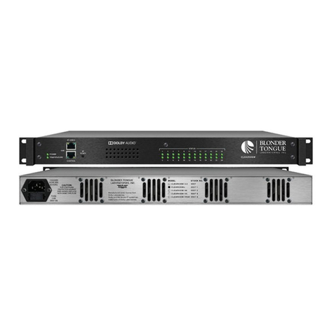
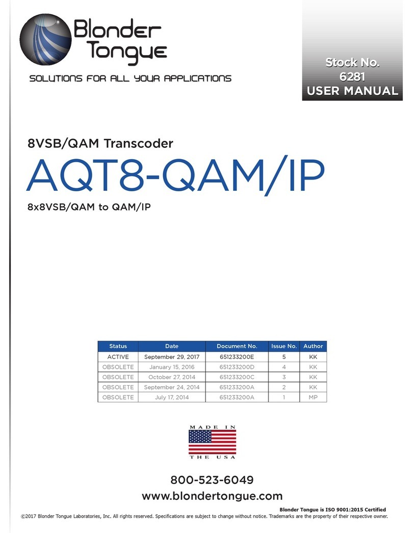
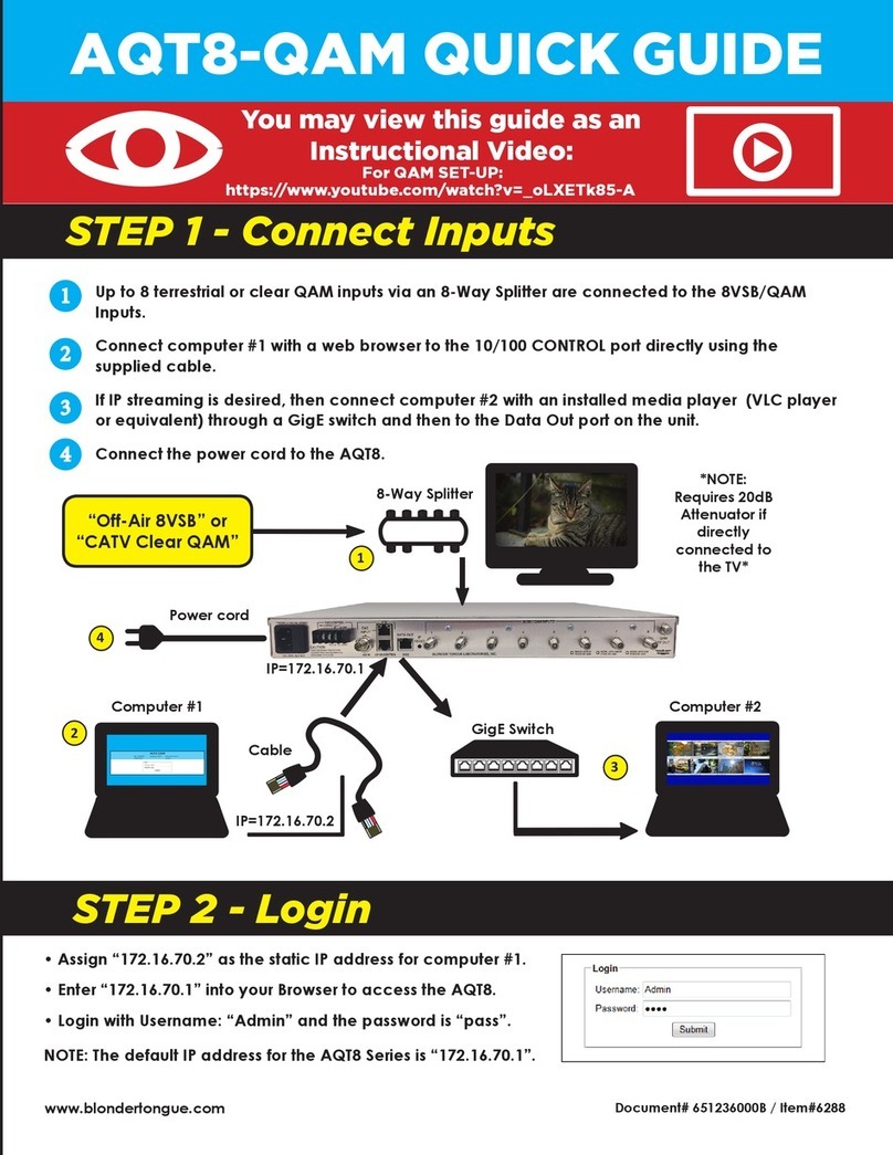
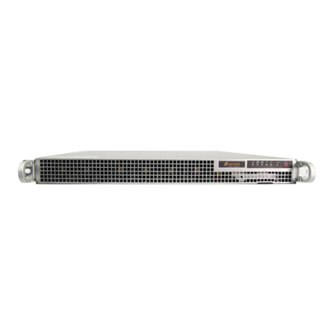
Blonder tongue AQT8 Series User manual

Stock # Model Name Description
6280B AQT8-IP 8x8VSB/QAM Input and IP Outputs
6281B AQT8-QAM/IP 8x8VSB/QAM Input and QAM/IP Outputs
All Rights Reserved. Specifications subject to change without notice. All trademarks are property of their respective owners.
AQT8 SeriesAQT8 Series
© Blonder Tongue Labs, Inc. ISO 9001:2015 Certified P/N: 651247000A | Rev: 110819

2AQT8 Series
User Manual
Returning Product for Repair (or Credit)
Before returning product, please contact the Blonder Tongue Service
Department at 1-800-523-6049, Ext. 4256 or visit our website:
located beneath the product image.
Blonder Tongue Laboratories, Inc.
One Jake Brown Road
Printed in the United States of America.
be the proprietary property of the registered owners.
intellectual property rights. Reverse engineering or disassembly is prohibited.

3AQT8 Series
User Manual
5
6
.............................................................................................................................. 6
................................................................................................................... 6
.................................................................................................................................... 9
............................................................................................................................................................ 10
........................................................................................................................... 10
........................................................................................................................... 10
............................................................................. 11
...................................................................................................................................................... 12
4.2 DETECTED ISSUES .................................................................................................................................................. 13
................................................................................................................................................... 13
4.4 IP OUTPUT STATUS ................................................................................................................................................ 13
4.5 RF OUTPUT STATUS ............................................................................................................................................... 14
......................................................................................................................................... 14
........................................................................... 16
....................................... 18
.................................................. 18
....................................................................... 19
.................................................................................................................. 19
........................................................................................................ 20
.................................................................................................................... 21
...................................................................................... 22
23
................................................................................................................................................................ 23
............................................................................................................................................................... 24
25
.......................................................................................................... 25
...................................................................................................................................... 25
8.3 AVAILABLE OUTPUT RESOURCES ......................................................................................................................... 26
................................................................................................................................... 26
........................................................................................................ 26

AQT8 Series
User Manual
(continued)
........................................................................................................................................................... 29
............................................................................................................................................................. 30
.................................................................................................................................................... 31
...................................................................................................................................................... 32
................................................................................................................................................. 34

5AQT8 Series
User Manual
åElevated Operating Ambient - If installed in a closed or multi-unit rack assembly,
the operating ambient temperature of the rack environment may be greater
than room ambient. Therefore, consideration should be given to installing
the equipment in an environment compatible with the maximum ambient
temperature per Section 2.3.
åReduced Air Flow - Installation of the equipment in a rack should be such that
the amount of air flow required for safe operation of the equipment is not
compromised.
åMechanical Loading - Mounting of the equipment in the rack should be such
that a hazardous condition is not achieved due to uneven mechanical loading.
åCircuit Overloading - Consideration should be given to the connection of
the equipment to the supply circuit and the effect that overloading of the
circuits might have on overcurrent protection and supply wiring. Appropriate
consideration of equipment nameplate ratings should be used when addressing
this concern.
åReliable Earthing - Reliable earthing of rack-mounted equipment should be
maintained. Particular attention should be given to supply connections other
than direct connections to the branch circuit (e.g. use of power strips).
åRead all safety and operating instructions before you operate the unit.
åRetain all safety and operating instructions for future reference.
å
åFollow all installation, operating, and use instructions.
åUnplug the unit from the AC power outlet before cleaning. Use only a damp
cloth for cleaning the exterior of the unit.
åDo not use accessories or attachments not recommended by Blonder Tongue,
as they may cause hazards, and will void the warranty.
åDo not operate the unit in high-humidity areas, or expose it to water or
moisture.
åDo not place the unit on an unstable cart, stand, tripod, bracket, or table. The
åDo not block or cover slots and openings in the unit. These are provided for
a radiator or heat register. Do not place the unit in an enclosure such as a cabinet
without proper ventilation. Do not mount equipment in the rack space directly
above or below the unit.
åOperate the unit using only the type of power source indicated on the marking
label. Unplug the unit power cord by gripping the plug, not the cord.
åThe unit is equipped with a three-wire ground-type plug. This plug will fit only
into a ground-type power outlet. If you are unable to insert the plug into the
outlet, contact an electrician to replace the outlet. Do not defeat the safety
purpose of the ground-type plug.
åRoute power supply cords so that they are not likely to be walked on or pinched
by items placed upon or against them. Pay particular attention to cords at plugs,
convenience receptacles, and the point where they exit from the unit.
The STOP sign symbol is intended to alert you to the
presence of REQUIRED operating and maintenance
(servicing) instructions that if not followed, may result in
product failure or destruction.
(servicing) instructions.
within the product's enclosure that may be of sufficient
magnitude to constitute a risk of electrical shock.
åBe sure that the outdoor components of the antenna system are grounded in
the following diagram:
åWe strongly recommend using an outlet that contains surge suppression or
ground fault protection. For added protection during a lightning storm, or when
the unit is left unattended and unused for long periods of time, unplug it from
the wall outlet and disconnect the lines between the unit and the antenna. This
will prevent damage caused by lightning or power line surges.
åDo not locate the antenna near overhead power lines or other electric light
or power circuits, or where it can fall into such power lines or circuits. When
installing the antenna, take extreme care to avoid touching such power lines or
circuits, as contact with them can be fatal.
åDo not overload wall outlets or extension cords, as this can result in a risk of fire
or electrical shock.
å
may touch dangerous voltage points or short out parts. This could cause fire or
electrical shock.
åDo not attempt to service the unit yourself, as opening or removing covers may
expose you to dangerous voltage and will void the warranty. Refer all servicing
to authorized service personnel.
åUnplug the unit from the wall outlet and refer servicing to authorized service
personnel whenever the following occurs:
oThe power supply cord or plug is damaged;
o
oThe unit has been exposed to rain or water;
oThe unit has been dropped or the chassis has been damaged;
oThe unit exhibits a distinct change in performance.
åWhen replacement parts are required, ensure that the service technician uses
replacement parts specified by Blonder Tongue. Unauthorized substitutions
may damage the unit or cause electrical shock or fire, and will void the warranty.
åUpon completion of any service or repair to the unit, ask the service technician
to perform safety checks to ensure that the unit is in proper operating condition.
6AQT8 Series
User Manual
•
• Accepts up to eight RF inputs in 8VSB/QAM format
•
•
• Accepts EAS input in ASI or IP formats
• Supports EAS switching-based on contact closure trigger, or +5 to +12 VDC input
• Comprehensive GUI-based remote monitoring and control via any standard Web browser
• )
*Model Dependent
The
maps the demodulated RF port content in MPTS format to IP output.
The AQT8 Series can accept encrypted QAM sources, and output the encrypted IP transport streams programs in MPTS or
SPTS formats, while preserving the MPEG tables (PAT, PMT, PSIP, VCT, and MGT) from the source. The unit allows the user to
EAS input, and terminal block contacts for triggering EAS messages.

AQT8 Series
User Manual
with Slo-Blo, 3.0A, 250 V Fuse.
1 2 3
"F" female connector for QAM RF output signal, 20dB lower than the actual
QAM RF output. Used for test purposes, without taking the unit out of service.
1
2
3
4
5
7
6
8 954
6 7
11
10
12
The current EAS behavior is an all or nothing program
program content replaced with the EAS program content.
RJ45 connector, 1000Base-T (GigE) interface for SPTS EAS IP input.
8

AQT8 Series
User Manual
RJ45 for 1000Base-T Ethernet (GigE) interface for IP DATA outputs.
to Factory Default values as follows:
center.
"F" female connector for QAM RF output.
10
11
12
9

AQT8 Series
User Manual
Input
Connectors
8VSB/QAM: 8x “F” Female
1x Common “F” Female
with Internal Active Splitter
8VSB Mode
Standard:
Tuning Range:
Data Rate:
Bandwidth:
Power Level:
Impedance:
ATSC Digital Television A/53E
UHF (Ch. 14-83), VHF (Ch. 2-13)
19.392 Mbps
6 MHz
-20 to +20 dBmV
75 Ω
QAM Mode
Standard:
Tuning Range:
Data Rate:
Bandwidth:
Power Level:
Impedance:
ITU-T J.83 - Annex B (64 and 256 QAM)
CATV Ch. 2-158 (STD, HRC, IRC)
38.8 Mbps (QAM 256); 26.97 Mbps (QAM
64) – Auto Detect
6 MHz
-15 to 20 dBmV (@ QAM 256)
-20 to 20 dBmV (@ QAM 64)
75 Ω
Emergency Alert System
ASI
Connector:
Standard:
IP
Connector:
Standard:
UDP/RTP:
Video Bit Rate:
Trigger Connectors:
Trigger Mechanism:
1x BNC Female
DVB-ASI; EN 50083-9 (SPTS)
1x RJ45
1000Base-T (GigE)
Supported (user-selectable)
The EAS program bit rate must not exceed
the lowest program video bit rate it will
replace. Example: EAS at 2.5 Mbps will
not work for a program at 2.0 Mbps.
Terminal Block
5-12 VDC & Dry Contact Closure
Output
IP
Connectors:
Standard:
UDP:
Address Assignment:
1x RJ45 (rear-panel)
1000Base-T Ethernet (GigE)
Supported
64x IPv4 SPTS address & port numbers
8x IPv4 MPTS address & port numbers
QAM (6281B Only)
Output Modules:
Connectors:
Modulation:
Standards:
DVB Symbol Rate:
Frequency Range:
Tuning:
No. of Programs:
RF Level:
RF Level Range:
Frequency Tolerance:
Frequency Stability:
Amplitude Flatness:
Phase Noise:
Spurious:
Broadband Noise:
Impedance:
QAM Spectrum:
Carrier Suppression:
Return Loss:
Signal-to-Noise Ratio (SNR):
MER:
I/Q Phase Error:
I/Q Amplitude Imbalance:
8x Fully Agile QAM
1x “F” Female
(rear-panel; for combined output)
QAM 64 and 256
ITU-T J.83; Annex B
5.360537 Msym/s (QAM 256)
5.056941 Msym/s (QAM 64)
54 to 1002 MHz
CATV Channel Selectable (CH. 2 to 158)
Variable (≤ 38.8 Mbps input source Pass-thru)
+40 dBmV, ± 1 dB
+30 to +45 dBmV, 1 dB increment
± 0.5 kHz @ 77 °F (25 °C)
± 5 kHz over 32 to 122 °F (0 to 50 °C)
± 0.25 dB (over 6 MHz channel)
-98 dBc (@ 10 kHz)
-60 dBc
-70 dBc (@ +40 dBmV output level, 5.5 MHz BW)
75 Ω
Inverted
45 dB
14 dB typical
42 dB typical
42 dB typical
Less than 1 degree
Less than 1%
Alarms/Monitoring/Control
Local Monitoring:
Local Control:
8x Channel LEDs
1x Power LED
1x IP Reset Button
Remote Monitoring/
Control:
GUI-based menu via standard Web browser
(1xRJ45 on rear panel; 1000Base-T; GigE)
General
Dimensions:
(W x D x H)
19.0” x 16.0” x 1.75”
(483 mm x 363 mm x 44 mm)
Power Supply:
Power Consumption:
110/230 VAC, 0.7/0.35A, 60/50 Hz
48 W (6281B - QAM/IP)
27 W (6280B - IP Only)
Weight: 7.4 lbs (3.35 kg)
Operating Temperature:
Storage Temperature:
32 to 122 ˚F (0 to 50 ˚C)
-13 to 158 ˚F (-25 to 70 ˚C)
Operating/Storage Humidity:
0 to 95% RH @ 35 ˚C max, non-
condensing

AQT8 Series
User Manual
•
•
•
To power the unit up, connect the IEC line cord to the receptacle on the rear panel. Then connect the other end to a
120 VAC power outlet. The input power receptacle is equipped with a fuse-holder and fuse (SLO-BLO, 3.0 Amp, 250V).
(Chrome or Firefox
is recommended)
same subnet as the unit's default IP address. To do so, follow these steps:
Plug one end of the Ethernet cable to the
the Ethernet cable to your computer.
The following steps explain how to do this for a computer with , or
(Note: It can be found using the search box in the Start Menu or for Windows 8.x, the Start Screen)
1
2
1
2

AQT8 Series
User Manual
Open a web browser on your computer (Chrome or Firefox is recommended)
and enter the following URL address
(Figure 4.2a) will appear.
click on the [
When logged in as Admin, the user has read and write permission. Only
(case-sensitive)
(case-sensitive)
1
2
before proceeding as follows:
As shown in Figure 4.2b
• RF
•
•
alongside the [
displays the unit’s serial number.
{
6
7

AQT8 Series
User Manual
Indicates the temperature of the
unit. (Figure 4.1b)
Indicates the model name of the unit
is indicated here as either AQT8-QAM/IP or AQT8-IP.
1
2
3
4
Indicates the current status of the unit. Status Levels and colors shown below:
Error
red in this state)
1
2
3
4
165.0 °F
73.9 °C
ErrorWarning
Normal Temperature
175.0 °F
79.4 °C

AQT8 Series
User Manual
The following 2 parameters are displayed as follows:
- Displays the link speed that is plugged in.
- Displays the amount of data used on that link.
Indicates the port on the unit for the Transport Stream source.
Indicates the IP and port assigned to Transport Stream 1.
M Indicates the IP and port assigned to MTS.
1
2
3
4
5
If any issues arise, the problem will be shown here and the color will correlate to the urgency of the issue. When there are
red and indicate what is causing the error.
28
Error Warning Normal Range
31
17
Error Warning Normal Range
19
1
2
3
The Source
The RF Channel column displays which RF channel the input is
locked to.
The
1 2 3
1
2
3
4
5

AQT8 Series
User Manual
QAM RF channel and frequency.
Indicates the serial number of the unit.
Secon 11.3
Indicates the modulator version for the unit.
1
2
3
4
1
2
3
4

AQT8 Series
User Manual
Indicates the physical port of the 8 RF inputs.
The input is connected to one of 8 dedicated RF ports located
on the rear panel of the unit. Each of these ports are labeled from 1 to 8.
down menu, select the desired channel/frequency (center) for each input.
and 4.3c on page 13.
1
2
3
4
5
6
8VSB
QAM256B
QAM64B
1
2
3
4
5
6

AQT8 Series
User Manual
Displays the Video encoding and bandwidth (Mb/S).
Displays programs sourced from all RF inputs
within the unit.
Displays the program number and may display
its source. An empty checkbox ( ) can be checked ( )
to select one or more programs to be added to the Output
Transports column. If there is no checkbox, the program
has already been selected and can be seen in the right
While the line is expanded, the following data for each
program is shown:
1
2
1
2
3
(Transport Stream) Select
be output both QAM and/or IP depending on the model.
Clicking the small arrow ( collapsed; expanded) beside each program will show or hide further choices or read-
only data.

AQT8 Series
User Manual
3
When one or more programs are selected from the
has been mapped to that TS #.
ALL available, or unused, programs as SPTS.
When one or more programs or program elements
the TSO #.
complete the process of removing all programs.
and programs and/or program elements
Displays the available number of programs that may be added to the
selected TSO. As each program is added, the number decreases accordingly.
output that they want to add one or more programs or program elements to.
4
5
6
8
7
9
4
7
5
8
6
9
Only programs which are being encoded will show up
in this column.
Displays the Program
channel. An empty checkbox ( ) can be checked
( ) to select one or more program or program elements
to be removed from the Cherry Picked Transports column.
When the line is expanded, the following data for each program
is shown:
Displays the RF source that the program is being
sourced from as well as the source stream name.
10
11
Example: O1, O2, etc.

AQT8 Series
User Manual
Each program can be located manually by clicking the arrows within either column in order to
the .
To add, locate the desired program or program data and check the empty box next to it.
From the pull-down menu, select which TS the chosen programs will be added to. Click and
An empty check box will always appear next to available programs. This check box will not appear
1
2
3
Each program can be manually located by clicking open the programs in order to view more in-
if the user knows which program(s) they intend to remove, and the
To remove, locate the desired program and check the box next to the program or program data
to select.
1
2
3
1
2
3
1
2

AQT8 Series
User Manual
setup of the programs. (See Figure 6.4)
The
The and
bold
italic red-colored
performed.
.
In (Figure 6.5), the following parameters can be set:
The user can use the drop down list to set the bitrate or choose custom bitrate and input the desired bitrate.
When the Transport Stream has been assigned to a QAM Output, the TS is QAM Locked.
Click
All
1
4
2
5 7
3
6 8
(Transport Stream)
3
1
2
be unique. Duplicates are not allowed.

AQT8 Series
User Manual
CVCT: Cable Virtual Channel Table
TVCT: Terrestrial Virtual Channel Table
OFF
Displays the RF Input that the channel is being sourced from as well as the source stream name.
The user must enter a unique output program number for each program.
and 1 to 999 for Cable.
The user may enter a minor channel number for the output program. The range is 1 to 99 Terrestrial and
0 to 999 for Cable.
this value higher than the previous program's output PID number.
5
2
4
3
1
6
7
8
1 2 3
5 64
following parameters will then be shown:
Other manuals for AQT8 Series
1
This manual suits for next models
2
Table of contents
Other Blonder tongue Transcoder manuals

Blonder tongue
Blonder tongue Clearview+ User manual

Blonder tongue
Blonder tongue AQT8-IP User manual

Blonder tongue
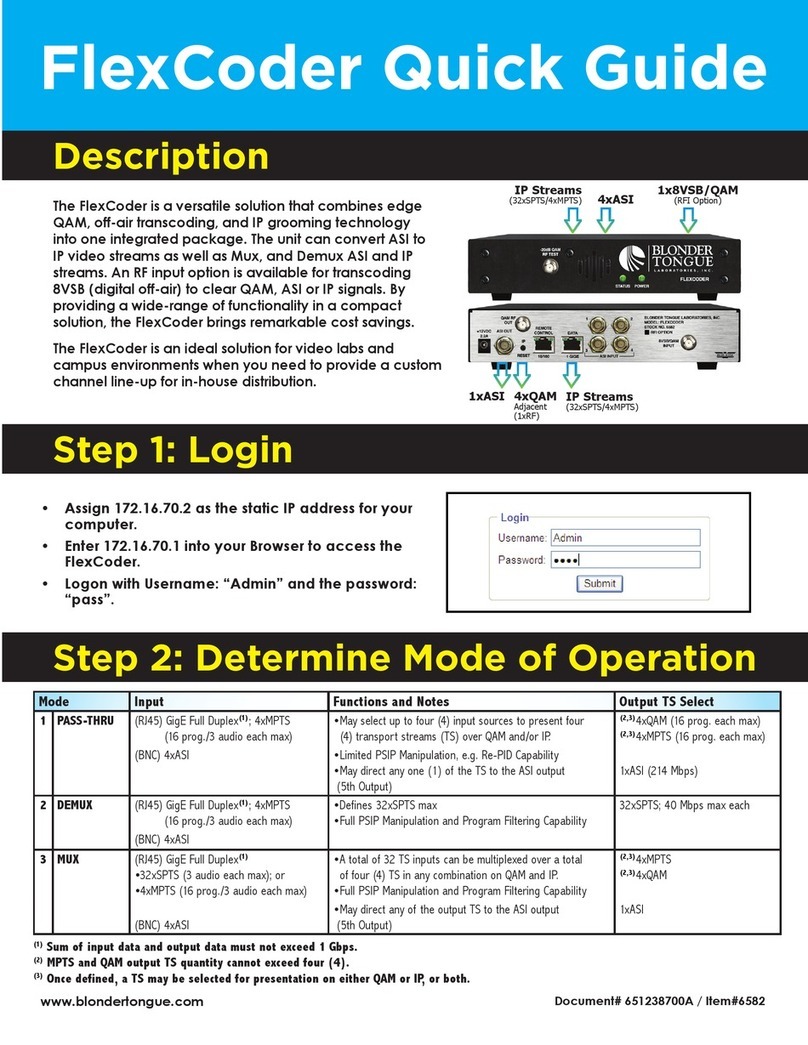
Blonder tongue FlexCoder User manual

Blonder tongue
Blonder tongue Clearview 4:2 User manual

Blonder tongue
Blonder tongue NXG-CV8 User manual

Blonder tongue
Blonder tongue Clearview 4:2 12 User manual

Blonder tongue
Blonder tongue Clearview 4:2 User manual

Blonder tongue
Blonder tongue Clearview 4:2 SD User manual

Blonder tongue
Blonder tongue AQT8-QAM User manual