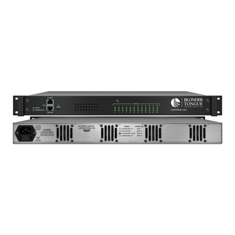
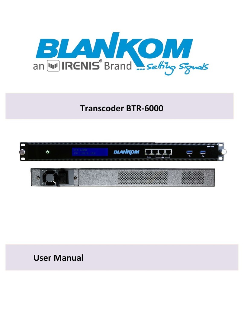
Blonder tongue FlexCoder User manual

FlexCoder Quick Guide
Description
Step 1: Login
Step 2: Determine Mode of Operation
Document# 651238700A / Item#6582
www.blondertongue.com
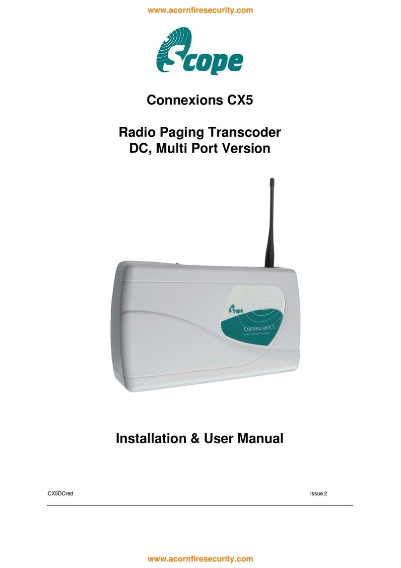
The FlexCoder is a versatile solution that combines edge
QAM, off-air transcoding, and IP grooming technology
into one integrated package. The unit can convert ASI to
IP video streams as well as Mux, and Demux ASI and IP
streams. An RF input option is available for transcoding
8VSB (digital off-air) to clear QAM, ASI or IP signals. By
providing a wide-range of functionality in a compact
solution, the FlexCoder brings remarkable cost savings.
The FlexCoder is an ideal solution for video labs and
campus environments when you need to provide a custom
channel line-up for in-house distribution.
• Assign 172.16.70.2 as the static IP address for your
computer.
• Enter 172.16.70.1 into your Browser to access the
FlexCoder.
• Logon with Username: “Admin” and the password:
“pass”.
1xASI
IP Streams
(32xSPTS/4xMPTS)
4xQAM
Adjacent
(1xRF)
4xASI
IP Streams
(32xSPTS/4xMPTS)
1x8VSB/QAM
(RFI Option)
Mode Input Functions and Notes Output TS Select
1PASS-THRU (RJ45) GigE Full Duplex(1); 4xMPTS
(16 prog./3 audio each max)
•May select up to four (4) input sources to present four
(4) transport streams (TS) over QAM and/or IP.
(2,3)4xQAM (16 prog. each max)
(2,3)4xMPTS (16 prog. each max)
(BNC) 4xASI •Limited PSIP Manipulation, e.g. Re-PID Capability
•May direct any one (1) of the TS to the ASI output
(5th Output)
1xASI (214 Mbps)
2DEMUX (RJ45) GigE Full Duplex(1); 4xMPTS
(16 prog./3 audio each max)
•Defines 32xSPTS max
•Full PSIP Manipulation and Program Filtering Capability
32xSPTS; 40 Mbps max each
(BNC) 4xASI
3MUX (RJ45) GigE Full Duplex(1)
•32xSPTS (3 audio each max); or
•4xMPTS (16 prog./3 audio each max)
•A total of 32 TS inputs can be multiplexed over a total
of four (4) TS in any combination on QAM and IP.
•Full PSIP Manipulation and Program Filtering Capability
(2,3)4xMPTS
(2,3)4xQAM
(BNC) 4xASI
•May direct any of the output TS to the ASI output
(5th Output)
1xASI
(1) Sum of input data and output data must not exceed 1 Gbps.
(2) MPTS and QAM output TS quantity cannot exceed four (4).
(3) Once defined, a TS may be selected for presentation on either QAM or IP, or both.
Under the “System Mode Select” drop down menu highlight the desired mode.
Click the “Reboot Unit” button.
After the unit has rebooted, log back into the unit again as in STEP 1.
STEP 3 - Changing Operation Mode
The DEMUX Mode is the default mode as shipped from the factory. If this is your desired mode then
proceed to STEP 4. To change to a different mode do the following:
From the Status page - Click on the Admin tab
1
2
3
2
3
1
CAUTION: Switching modes results in all IP settings to revert back to the factory defaults. This action should
never be performed while accessing the unit remotely, as communication to the FlexCoder will be lost. The
property will require a service call to congure the new mode settings and the IP addresses of the FlexCoder
should this occur.
NOTE: Do not press “SAVE” when changing modes. The “Reboot Unit” Button will apply the new Mode Setting.

STEP 4 - Main > Input Configuration
For the Input Conguration screen, DEMUX and PASS-THRU Modes allow 4 congurable Transport
Streams. MUX Mode allows up to 32 congurable Transport Streams (TS). Source selections for each
TS are: IP(UDP), IP(RTP), RF(optional), ASI#1 to ASI#4 and Disabled.
IP selections require Address and Port entries
RF (RFI option) channel setting is set under the QAM Cong tab.
ASI #1 to #4 are the rear panel input connectors
Once all entries have been made click the “Save” button
1
2
3
1
2
3
The “RF Channel”
column will only
display when the
unit is installed
with RFI option.
When the unit is
not installed with
RFI option, the
“RF” source will
be greyed out.
The setting parameters are the same between DEMUX and MUX modes with the exception of the
number of Input and Output TS’. The DEMUX has (4) Input TS’ with up to (32) Output TS’ whereas the
MUX Mode is the complete opposite with (32) Input and (4) Output TS’s.
Select the desired programs from the Input TS’s under the green header (#1) for each output TS
(TS0#) using the “Selection Control” and click on the “Add =>” button.
To remove programs from the Output, click on the check box and then click the “<= Remove”
button.
DEMUX & MUX MODES ONLY
A
1
2
2
1
STEP 5 - Main > TS Map Settings
PASS-THRU MODE (Not Available, go to Step 6)
B

TS ID: user must enter the identication number for the output TS. The range is 1 to 65535. The TS
ID assigned must be unique.
Bit rate Select: User selects from the 4 proles set in the General TS Conguration section.
VCT: MPEG Virtual Channel Table selections are off, TVCT (terrestrial) and CVCT (cable)
Modulation Mode: user can select the modulation mode for the MPEG TS table. Options are:
Reserved, Analog, QAM64, QAM256, 8-VSB, and 16-VSB
Out of Band: an out-of-band (OOB) is a channel which is the combination of the forward and
reverse OOB channels. When a cable virtual channel is agged as being out-of-band, it is
carried on the out-of-band channel. Possible options are Enable, and Disable. When Enabled,
assigns the OOB bit in the TS packet and labels the TS as out-of-band.
STEP 6 - Main > TS Configuration
The setting parameters are basically the same between DEMUX and MUX modes with the exception
of the number of Output TS’ and the “Re-PID” option (Disable/Enabled) on DEMUX mode.
General TS Conguration
There are (4) User TS Bitrate preset proles. The available selections are 38.81, 19.39, 12.00, 8.00
Mbps or User Dened.
TS Output Conguration
If Re-PID’ing (only in DEMUX MODE) is desired, select “Enabled” on the corresponding TS0. Output
PID and Programs number can then be changed. The Default is “Disabled” with these elds grayed
out. On MUX Mode the PIDs can always be changed.
DEMUX & MUX MODES
A
1
2
3
4
5
1 2
6
3
7 8 9
4 5

Program Number: user must enter a unique output program number for each program. PMT
(Program Map Table) provides information on each program present in the transport stream
such as program number, and the list of the elementary streams (audio, video or data).
Short Name: user may enter the short name of the channel. Up to 7 alphanumeric characters
are allowed.
Major Channel Number: user may enter the major channel number for the output program. The
range is 1 to 99 for Terrestrial and 1 to 999 for Cable (CVCT).
Minor Channel Number: The minor channel number for the output program is 1 to 99 for Terrestrial
(TVCT) and 0 to 999 for Cable (CVCT).
NOTE: when zero (0) is entered as a minor channel, it sets the encoder to provide a one part virtual
channel number as entered in the major channel eld. For example, a major channel of “205” with a
minor channel of “0” will be displayed as “205” on a TV. A major channel of “205” with a minor channel
of “1” will be displayed on a TV as “205-1”.
Once all entries have been made click the “Save” button.
STEP 6 - Main > TS Configuration
6
7
8
9
The PASS-THRU mode is a read-only screen when the RePID Inputs is set to “Disabled”. All information
is based upon the input programs. When RePID is set to “Enabled”, the user is permitted to modify
the TS Output Conguration and Output Mapping elds. Refer to the eld descriptions under the
DEMUX/MUX section above.
PASS-THRU MODE
B

QAM Output Conguration
Select the channel for the 1st QAM. The next 3 will be automatically assigned. TS01 is mapped
to QAM 1, TS02 is mapped to QAM 2 and so on.
Ensure all outputs are on and CW mode is not enabled.
RF Input Option (Stk# 6582-RFI) Conguration
Input Channel: Drop down list of channel/frequency dependent upon MAP selection.
QAM Mode: Choices are 256B and 64B
QAM Map: Choices are: STD, HRC and IRC (QAM) and 8VSB for OTA.
STEP 7 - Main > QAM Configuration
ALL MODES
PASS-THRU & MUX MODE Only
A
B
1
4
2
5
3
Once all entries have been made click the “Save” button to apply changes.
1
2
3
4
A
B
5

IP Type: There are two available options (RTP & UDP). Select the one that matches the protocol
used by the receiving equipment.
IP Address and IP Port: The user must enter the IP Address and Port number.
ASI: One output TS (only) can be simultaneously provided as an ASI output by selecting Enabled.
STEP 8 - Main > Output
DEMUX MODE
A
1
2
3
1 3
2
Settings are the same as the DEMUX Mode with the addition of the QAM eld. Selection is either
“Disabled” or the RF channels selected under QAM Conguration in STEP 7. TS01 is QAM #1, TS02
is QAM #2, etc.
MUX & PASS-THRU MODES
B
1
1

STEP 9 - Main > Status
Once all the settings have been completed, use the STATUS screen to review.
CONTACT BT FOR MORE INFO | TECH SERVICES: 732-679-4000 x 4358
Table of contents
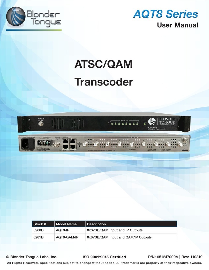
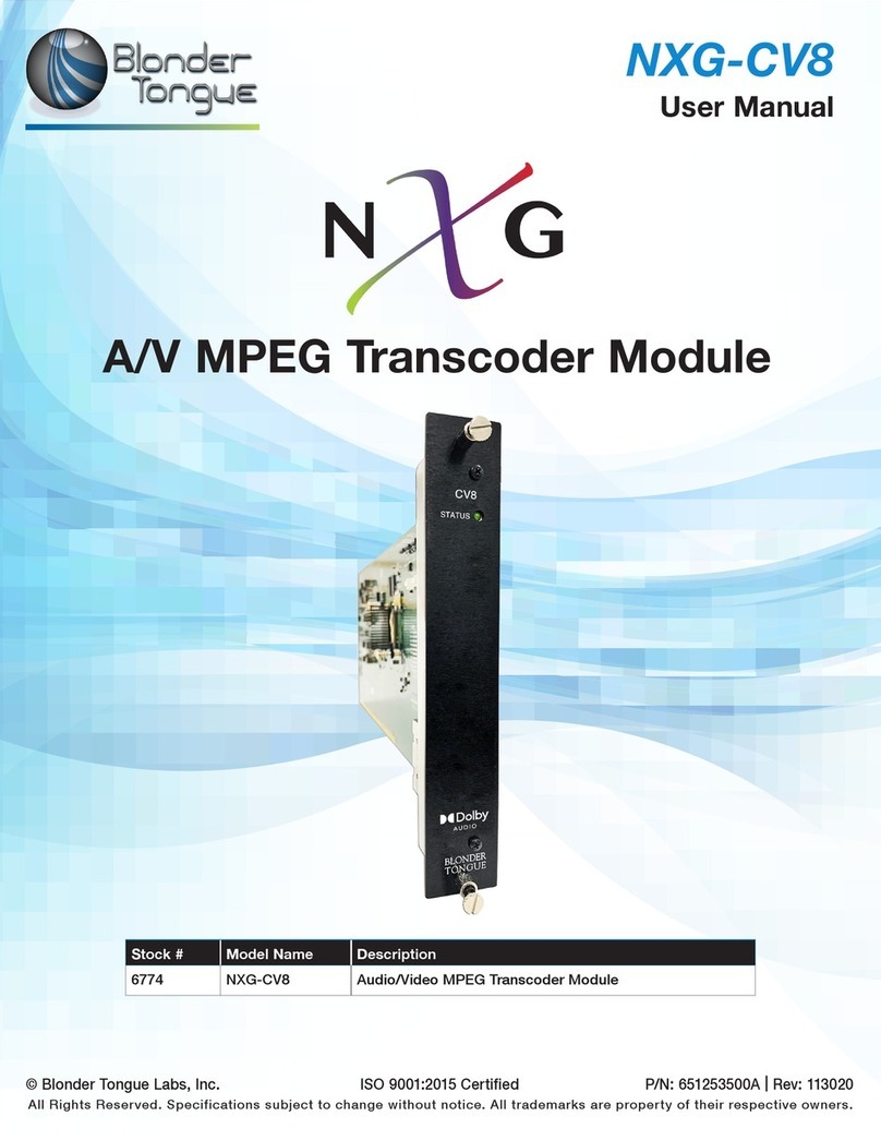
Other Blonder tongue Transcoder manuals

Blonder tongue
Blonder tongue Clearview 4:2 User manual

Blonder tongue
Blonder tongue AQT8-IP User manual

Blonder tongue
Blonder tongue Clearview 4:2 12 User manual

Blonder tongue
Blonder tongue AQT8 Series User manual

Blonder tongue
Blonder tongue Clearview 4:2 SD User manual

Blonder tongue
Blonder tongue Clearview 4:2 User manual

Blonder tongue
Blonder tongue AQT8-QAM User manual

Blonder tongue
Blonder tongue NXG-CV8 User manual

Blonder tongue
Blonder tongue Clearview+ User manual