Blue Bay SP3012B User manual

1

2
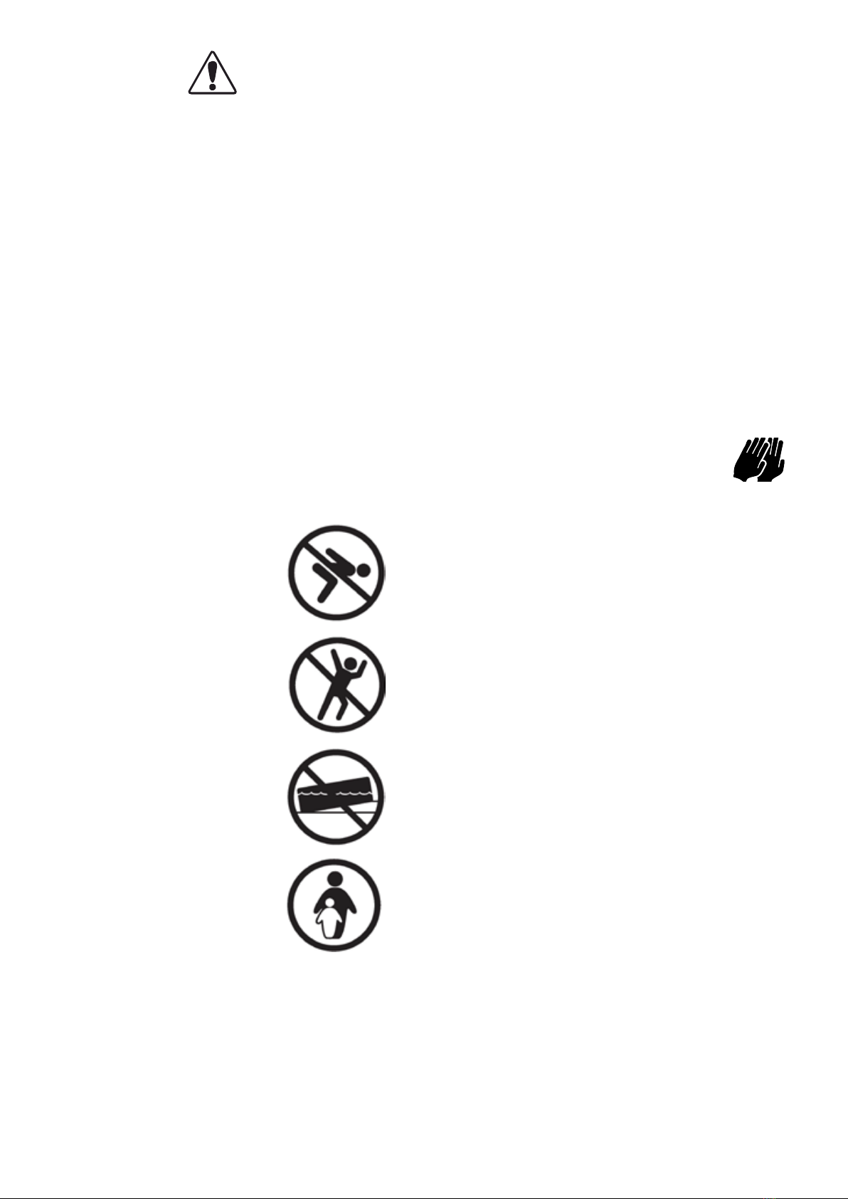
WARNING!
To lessen your risk of serious injury or death, follow these rules:
IMPORTANT SAFETY INSTRUCTIONS
The following instructions contain important safety information, we strongly encourage you to read these
important safety instructions and abide by them when using this pool. When installing and using this elec-
trical equipment, basic safety precautions should always be followed, This includes the following.
WARNING!
CHILDREN HAVE DROWNED IN
PORTABLE SWIMMING POOLS.
ENSUREACTIVEADULT SUPER-
VISION AT ALL TIMES. DO NOT
LEAVE CHILDREN UNSUPERVISED IN OR
AROUND THE POOL - KEEP THEM WITH-
IN ARMS REACH. POOL FENCING LAWS
APPLY TO THIS POOL. CONSULT YOUR
LOCAL GOVERNMENT AUTHORITY FOR
FENCING REQUIREMENTS
READ AND FOLLOW ALL INSTRUCTIONS
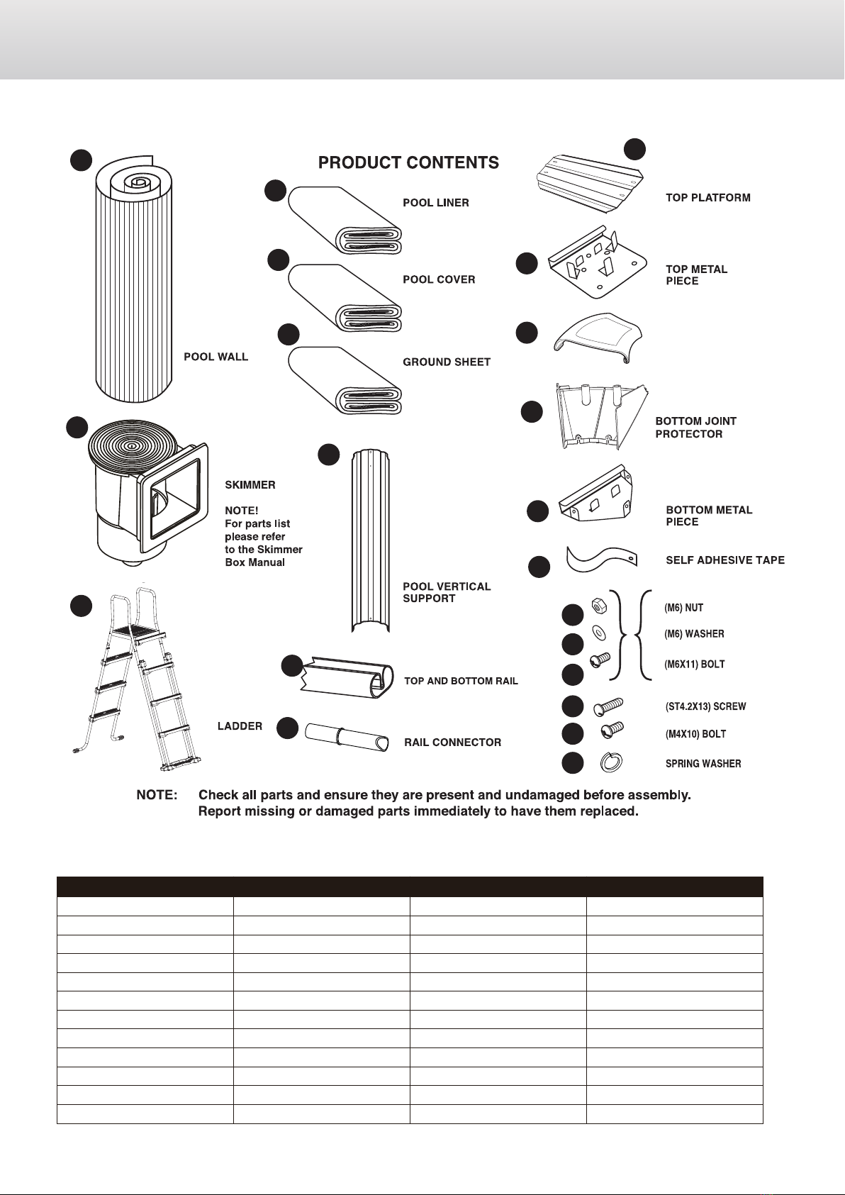
NOTE - Please examine equipment before use. If there are any damaged or missing parts
at the time of purchase, do not assemble or operate until parts are replaced.
WARNING - Consult your local council, state government or water authority in regards to the use
of water and/ or water restrictions relating to this product.
WARNING - Pool fencing laws aect this product, consult your local council and state government.
Abide by state and federal law requirements such as fencing, enclosures, childproof
gates, etc.
WARNING - Water attracts children; Always remove pool ladder when not in use. Store in a place
not accessible to children.
DANGER - Prevent the Risk of Accidental Drowning. Extreme caution must be exercised to pre
vent unauthorized access by children. To avoid accidents, ensure that children can not
use the Pool unless they are supervised by an adult at all times.
NEVER LEAVE CHILDREN UNATTENDED.
WARNING - RISK OF ELECTRIC SHOCK. Connect Filter Pump only to a grounding type recep
tacle protected by an RCD (Residual Current Device). Use a qualied electrician to
install the RCD, which has a maximum rate of 30mA.
WARNING - Know where the cut-o switch for your pump is at all times, so you can turn it o in
an emergency. It is necessary to have the RCD (Residual Current Device) Cut-O
Switch plug accessible after installation of the Pool.
WARNING - Never use an extension cord to connect the lter pump to a power source. Doing so could
cause damage to the lter pump system.
3
WARNING!
To lessen your risk of serious injury or death, follow these rules:
WARNING - To avoid electrocution, do not permit electric devices i.e. light, telephone, radio, televi
sion, hair dryer, etc within 2.5m(8ft) of this Pool.
WARNING - RISK OF ELECTRIC SHOCK. Never operate any electrical appliance when in the
Pool or when your body is wet.
WARNING - To reduce the risk of injury or hazard, have any damaged cord replaced immediately
by the manufacturer, its service agent, or similarly qualied persons.
WARNING - Do not bury electric cord. Avoid using lawn mowers, hedge trimmers and other
garden equipment near or around the Metal Wall Pool and electrical cord.
WARNING - NEVER swim or bathe in the Pool during rain or an electrical storm or if there is a
threat of lightning in the vicinity of the Pool.
WARNING - NEVER allow horseplay, diving or jumping into or around the Metal Wall Pool.
Never enter the Pool via any decks or other raised surfaces; the water level of the
Pool is shallow. Serious injury, paralysis or death could result.
CAUTION - It is advisable to wear protective gloves when assembling pool
NO DIVING
NO JUMPING
NO SLOPING GROUND
USE ONLY UNDER
COMPETENT SUPERVISION
SAVE THESE INSTRUCTIONS
4
SP3012B
SP3612B
SP4612B
SP5512B
SP6412B
SP7312B
SP3013B
SP3613B
SP4613B
SP5513B
SP6413B
SP7313B
Φ3000xH1200mm
Φ3600xH1200mm
Φ4600xH1200mm
Φ5500xH1200mm
Φ6400xH1200mm
Φ7300xH1200mm
Φ3000xH1300mm
Φ3600xH1300mm
Φ4600xH1300mm
Φ5500xH1300mm
Φ6400xH1300mm
Φ7300xH1300mm
1048
1248
1548
1848
2148
2448
1052
1252
1552
1852
2152
2452
Φ10'x48"
Φ12'x48"
Φ15'x48"
Φ18'x48"
Φ21'x48"
Φ24'x48"
Φ10'x52"
Φ12'x52"
Φ15'x52"
Φ18'x52"
Φ21'x52"
Φ24'x52"
Item No. Pool Dimension (metric) Item No. Pool Dimension (imperial)
Ladder, Pool Cover and Groud Sheet may not included in the pack age due to dierent
conguration, consult your local pool dealer for these parts.
Images and objects may dier .
1
2
4
3
6
14
11
5
8
9
12
10
16
17
21
18
15
20
19
22
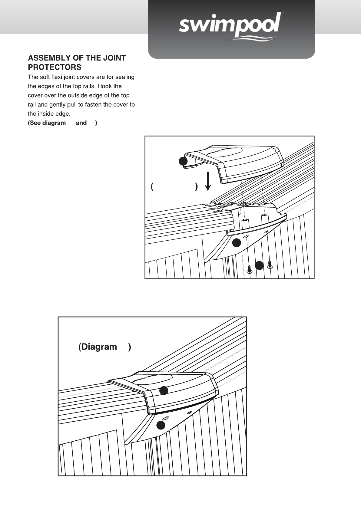
UPPER JOINT PROTECTOR
13
*
*
*
*
5
19
1
2
3
4
5
6
7
8
9
10
11
12
13
14
15
16
17
18
19
20
21
22
20001001
20001003
20001007
20001008
20001009
20001010
20001011
20001012
20001013
20001015
20001016
20001017
20001018
20001019
20001020
20001021
20001022
20001023
20001024
20001025
20001026
20001027
POOL WALL
POOL LINER
SKIMMER
POOL COVER
GROUND SHEET
LADDER
MAINTAINCE KIT
TOP METAL PIECE
UPPER JOINT PROTECTOR
BOTTOM METAL PIECE
TOP & BOTTOM RAIL
BOTTOM JOINT PROTECTOR
TOP PLATFORM
POOL VERTICAL SUPPORT
RAIL CONNECTOR
SELF-ADHESIVE TAPE
M6 NUT
M6X11 BOLT
M4X10 BOLT
ST4.2X13 SCREW
M6 WASHER
SPRING WASHER
1
1
1
1
1
1
1
8
8
8
16
8
8
8
32
1
58
58
48
32
58
32
1
1
1
1
1
1
1
8
8
8
16
8
8
8
32
1
58
58
48
32
58
32
1
1
1
1
1
1
1
10
10
10
20
10
10
10
40
1
66
66
60
40
66
40
1
1
1
1
1
1
1
12
12
12
24
12
12
12
48
1
74
74
72
48
74
48
1
1
1
1
1
1
1
14
14
14
28
14
14
14
56
1
82
82
84
56
82
56
1
1
1
1
1
1
1
16
16
16
32
16
16
16
64
1
90
90
96
64
90
64
PART NO. PARTS DESCRIPTION SP3012B
1048
SP3612B
1248
SP4612B
1548
SP5512B
1848
SP6412B
2148
SP7312B
2448
ENDEAVOUR ROUND POOL
#

6
19
13
12
19
1
2
3
4
5
6
7
8
9
10
11
12
13
14
15
16
17
18
19
20
21
22
20001001
20001003
20001007
20001008
20001009
20001010
20001011
20001012
20001013
20001015
20001016
20001017
20001018
20001019
20001020
20001021
20001022
20001023
20001024
20001025
20001026
20001027
PART NO. PARTS DESCRIPTION SP3013B
1052
SP3613B
1252
SP4613B
1552
SP5513B
1852
SP6413B
2152
SP7313B
2452
ENDEAVOUR ROUND POOL
#
POOL WALL
POOL LINER
SKIMMER
POOL COVER
GROUND SHEET
LADDER
MAINTAINCE KIT
TOP METAL PIECE
UPPER JOINT PROTECTOR
BOTTOM METAL PIECE
TOP & BOTTOM RAIL
BOTTOM JOINT PROTECTOR
TOP PLATFORM
POOL VERTICAL SUPPORT
RAIL CONNECTOR
SELF-ADHESIVE TAPE
M6 NUT
M6X11 BOLT
M4X10 BOLT
ST4.2X13 SCREW
M6 WASHER
SPRING WASHER
1
1
1
1
1
1
1
8
8
8
16
8
8
8
32
1
61
61
48
32
61
32
1
1
1
1
1
1
1
8
8
8
16
8
8
8
32
1
61
61
48
32
61
32
1
1
1
1
1
1
1
10
10
10
20
10
10
10
40
1
69
69
60
40
69
40
1
1
1
1
1
1
1
12
12
12
24
12
12
12
48
1
77
77
72
48
77
48
1
1
1
1
1
1
1
14
14
14
28
14
14
14
56
1
85
85
84
56
85
56
1
1
1
1
1
1
1
16
16
16
32
16
16
16
64
1
93
93
96
64
93
64
7
Selecting a Suitable Site
Carefully select the site for your new pool. This is the most important decision you will have
to make to ensure the safety and success of your pools construction. An incorrect site could
cause problems in the future that may cause injury, death or nancial loss. Read carefully the
check list set out below when selecting your site.
Acceptable:
Flat, level, rm and dry ground with easy ac-
cess to all sides of the pool exposed to direct
sunlight, preferably in the morning. Safe ac-
cess to electricity for running the lter pump
and other pool accessories. Access to mains
water source. Protection from wind.
Not acceptable:
Sloping ground.
Concrete, Asphalt, Sandy Gravel and Swampy
ground.
Close to wooden construction e.g.
Pergola’s and decking.
Next to deciduous or leafy trees.
Over-head wires and clothes line.
Drains, electric wires or gas pipelines
underneath the site.
Poor or little drainage or high ood risk loca-
tions.
High wind conditions.
Tools Required:
•Phillips head screw
driver
• Small Shifter
• Clothes Pegs
• Spirit Level
• Sharp Knife
• Site excavation tools
• Protective Gloves
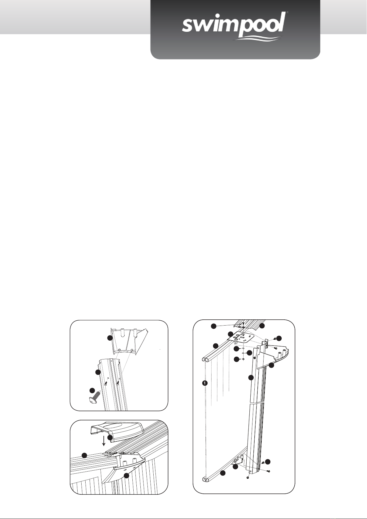
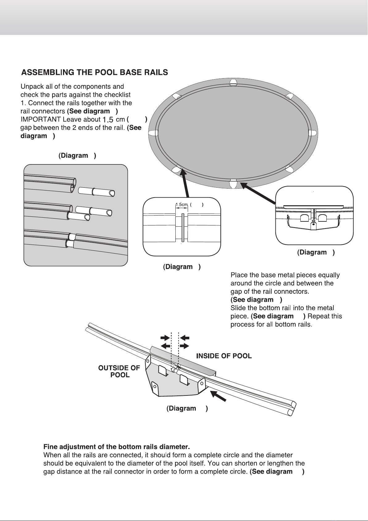
TOP PLATFORM, VERTICAL AND HORIZONTAL RAILS AND PROTECTOR ASSEMBLY
19
13
12
19
1
2
3
4
5
6
7
8
9
10
11
12
13
14
15
16
17
18
19
20
21
22
20001001
20001003
20001007
20001008
20001009
20001010
20001011
20001012
20001013
20001015
20001016
20001017
20001018
20001019
20001020
20001021
20001022
20001023
20001024
20001025
20001026
20001027
PART NO. PARTS DESCRIPTION SP3013B
1052
SP3613B
1252
SP4613B
1552
SP5513B
1852
SP6413B
2152
SP7313B
2452
ENDEAVOUR ROUND POOL
#
POOL WALL
POOL LINER
SKIMMER
POOL COVER
GROUND SHEET
LADDER
MAINTAINCE KIT
TOP METAL PIECE
UPPER JOINT PROTECTOR
BOTTOM METAL PIECE
TOP & BOTTOM RAIL
BOTTOM JOINT PROTECTOR
TOP PLATFORM
POOL VERTICAL SUPPORT
RAIL CONNECTOR
SELF-ADHESIVE TAPE
M6 NUT
M6X11 BOLT
M4X10 BOLT
ST4.2X13 SCREW
M6 WASHER
SPRING WASHER
1
1
1
1
1
1
1
8
8
8
16
8
8
8
32
1
61
61
48
32
61
32
1
1
1
1
1
1
1
8
8
8
16
8
8
8
32
1
61
61
48
32
61
32
1
1
1
1
1
1
1
10
10
10
20
10
10
10
40
1
69
69
60
40
69
40
1
1
1
1
1
1
1
12
12
12
24
12
12
12
48
1
77
77
72
48
77
48
1
1
1
1
1
1
1
14
14
14
28
14
14
14
56
1
85
85
84
56
85
56
1
1
1
1
1
1
1
16
16
16
32
16
16
16
64
1
93
93
96
64
93
64
9
12
18
11 21
19
13
22
14
12
17
11
10
19
8
12
14
20
13
56

8
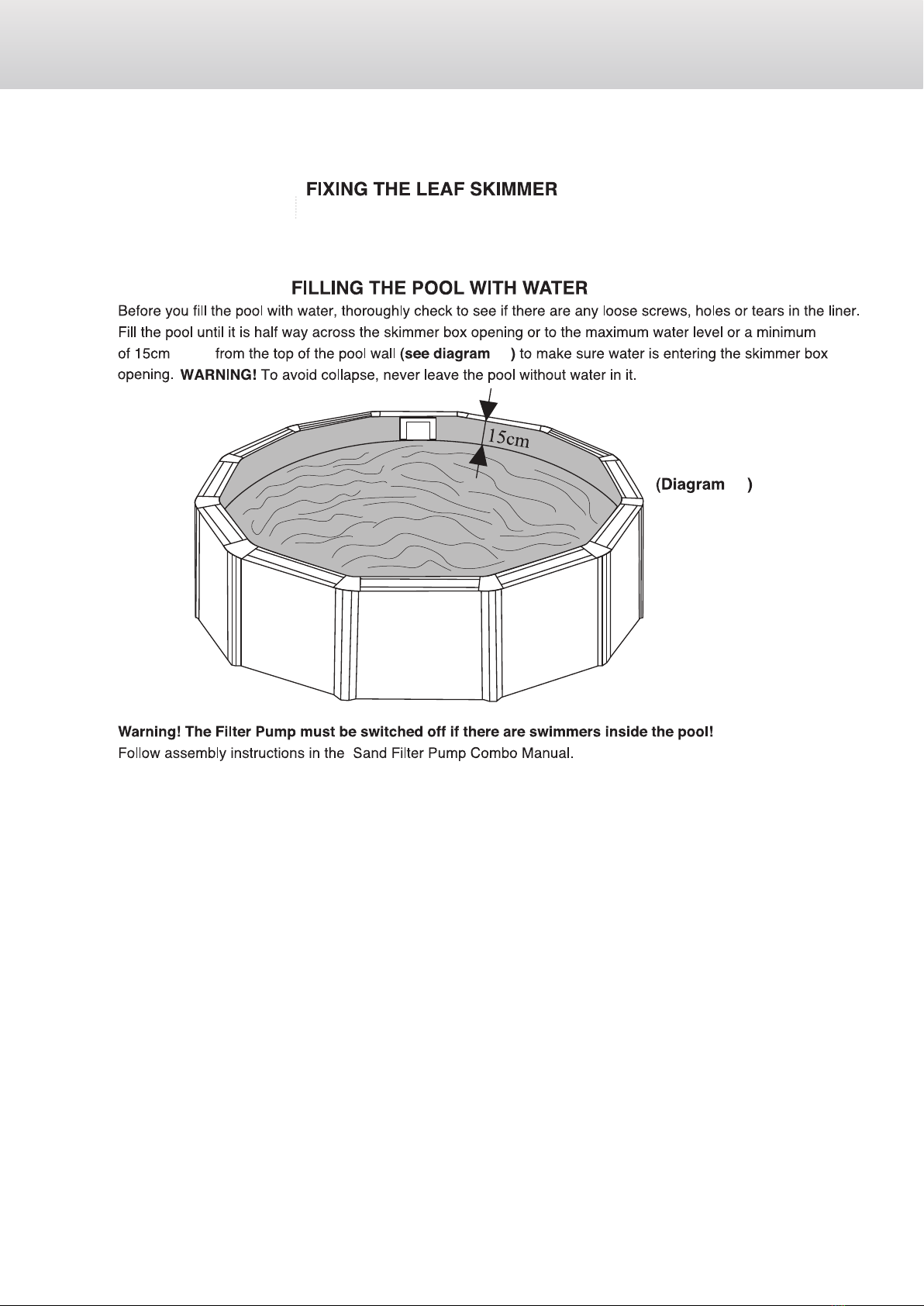
Pool Setup
GROUND PREPARATION
The preparation of the ground is the most important step in the installation of the
pool.
Mark o your pool area by driving sta kes. Have a helper hold a tape measure or a
string and mark o the pool perimeter using our or chalk. Remove sod inside the
pool area to a distance of 30cm (1 ft) beyond dimensions shown in the plot layout
around entire perimeter of pool.
9
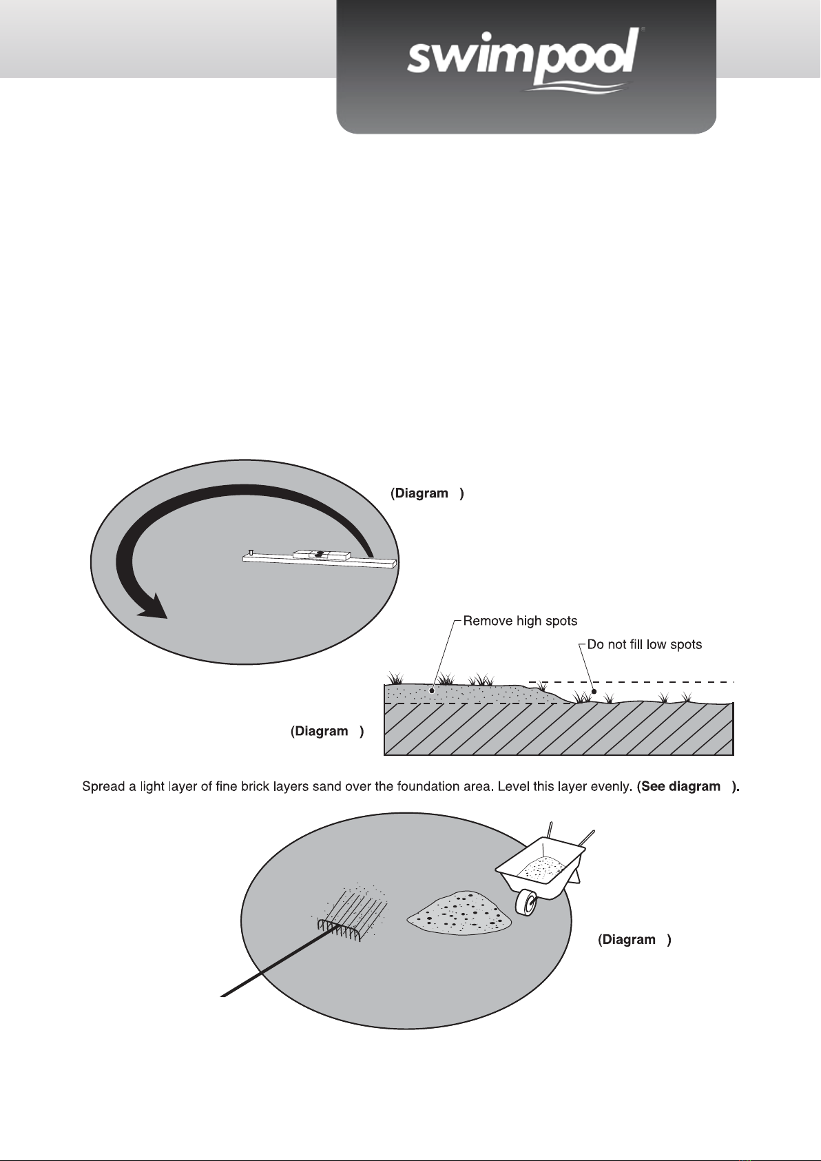
Levelling the Area
Warning! Levelling is extremely important: take as much time
as possible to work out a site that is completely rm and levelled.
Use a carpenter’s level and straight edge to ensure that the site is complete-
ly level, at and rm! (See diagram 5) The pool contains a huge amount of wa-
ter and thousands of kilos of weight. Should the pool collapse due to unlevelled
ground, it could cause a lot of damage to property and even human injury or death!
Remove the higher ground rather than lling the low laying ground (see diagram 6)
Attention! Always remove grass and stones within the circle.
Use ground sheet to ensure that the grass doesn’t penetrate the pool liner and
cause damage.
1
2
3
3
10
4
0.6"
0.6"
4
5
5
6
6
7
7
7
8
9
9
10 11
11
12
10
8
910
11
4
0.6"
0.6"
4
5
5
6
6
7
7
7
8
9
9
10 11
11
12
10
8
910
12
12
13
13
14
18
18
17
17
14
1615
1615
0.8"
0.8"
0.8"
INSIDE OUTSIDE
16
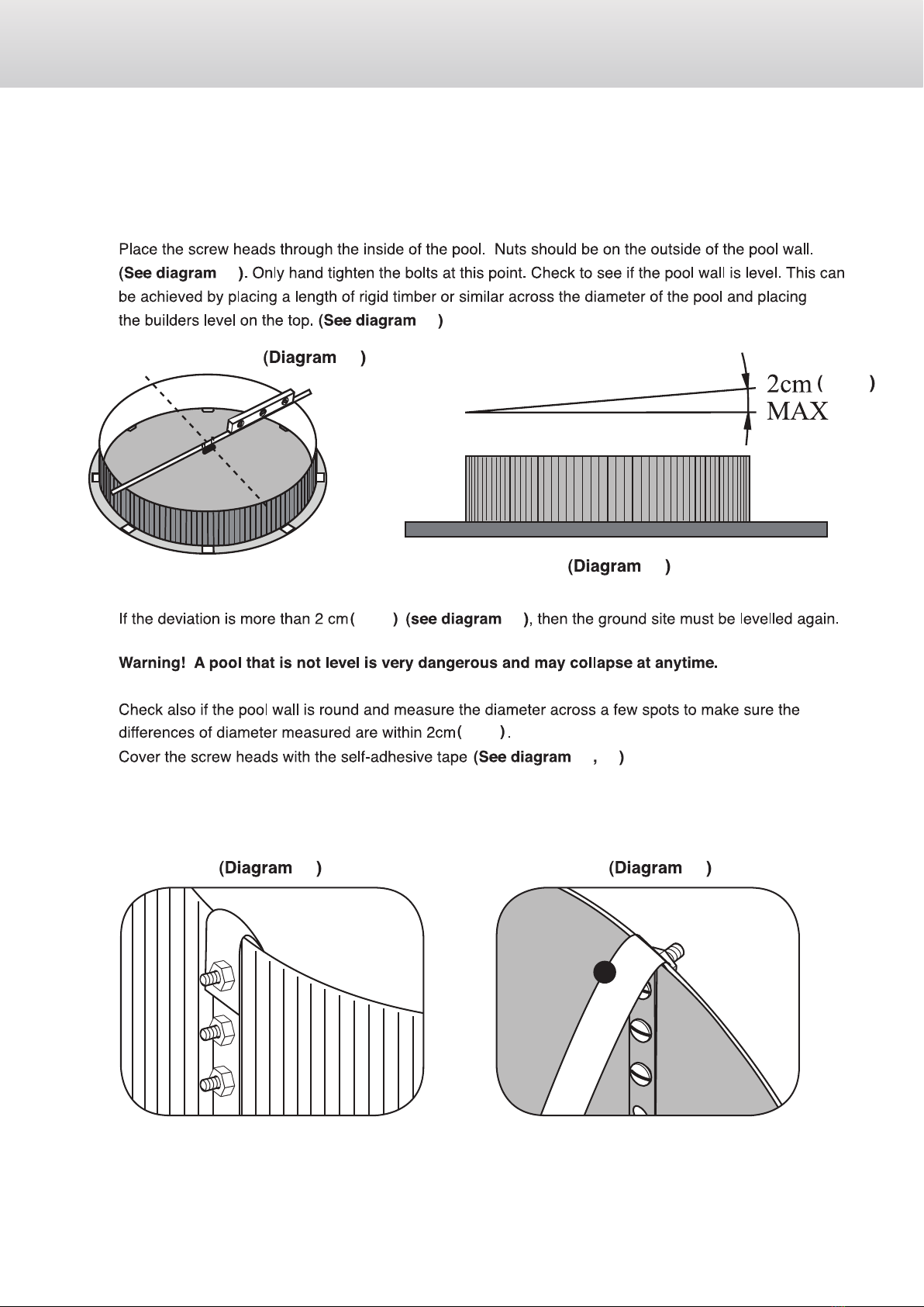
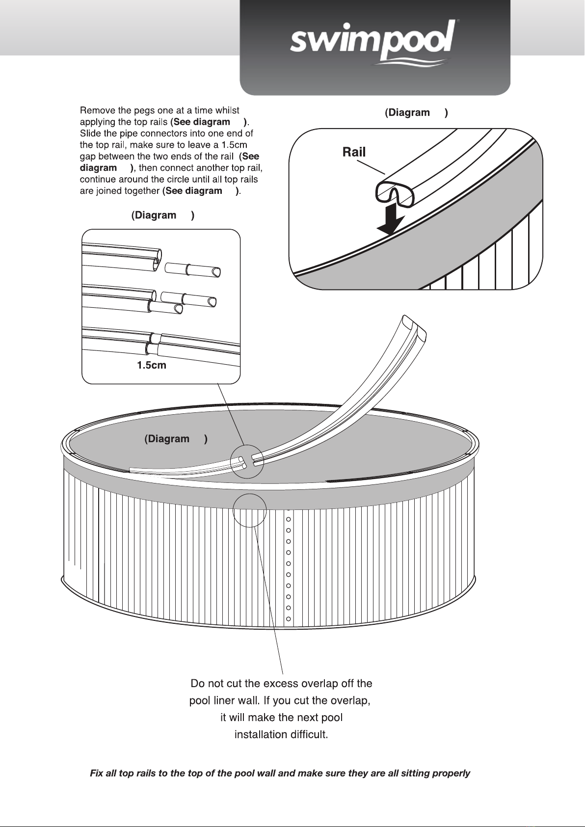
Place the Self Adhesive Tape over the
exposed screw heads to seal them off.
6"
6"
6"H x 6" W
11 12

13
12
13
13
14
18
18
17
17
14
1615
1615
0.8"
0.8"
0.8"
INSIDE OUTSIDE
16
Place the Self Adhesive Tape over the
exposed screw heads to seal them off.
6"
6"
6"H x 6" W
11 12

14
19 20
19 20
21
22
21 22
23 23
24
24
25
25
( )
( )
3"
( )
( 0.6" )
( 0.6" )
3"
( )
( )
1"-2"
72°F
60°F
13 14
15
19 20
19 20
21
22
21 22
23 23
24
24
25
25
( )
( )
3"
( )
( 0.6" )
( 0.6" )
3"
( )
( )
1"-2"
72°F
60°F
13 14
16
26
27
26
27
27
30
31
30
31
28
29
29
28
18
21
13
14
12
20
8
8
22
17
15 16
ST4.2X13
17
26
27
26
27
27
30
31
30
31
28
29
29
28
18
21
13
14
12
20
8
8
22
17
15 16
ST4.2X13
18
32
32
33
33
34 35
35
18
11 21 22
17
12
14
19
10
11
13
19
8
17 18
9
20
12
12
9
Diagram 34
Fix with the screws provided.
19
32
32
33
33
34 35
35
18
11 21 22
17
12
14
19
10
11
13
19
8
17 18
9
20
12
12
9
Diagram 34
Fix with the screws provided.
20
6"
( )
6"
( )
36
36
For antirusting, all edges of cut out have to be covered by vinyl tape or rusting paint.
Begin the installation of the through the wall skimmer. Follow separate skimmer installations.
6"
( )
19 20
This manual suits for next models
11
Table of contents


