Blue Diamond PICKUP BROOM 2 Series User manual

Operation and Maintenance Manual
Pickup Broom
Series 2
888-376-7027 | BlueDiamondAttachments.com
Register your
WARRANTY
within 30 days
of purchase
60” – 116512
72” – 116517
84” – 116522
96” – 116527
G B – 116555

Blue Diamond® Attachments2
Thank you for your decision to purchase a Blue Dia-
mond® Series 2 Pickup Broom. To ensure maximum
performance of your equipment, it is mandatory that you
thoroughly study the Operator’s manual and follow the
recommendations. Proper operation and maintenance
are essential to maximize equipment life and prevent
personal injury.
Operate and maintain this equipment in a safe man-
ner and in accordance with all applicable local, state,
and federal codes, regulations and /or laws. Follow all
on-product labeling and instructions.
Make sure that all personnel have read this Operator’s
Manual and thoroughly understand safe and correct
operating, installation and maintenance procedures.
Blue Diamond is continually working to improve its
products. Blue Diamond reserves the right to make any
improvements or changes as deemed practical and pos-
sible without incurring any responsibility or obligation
to make any changes or additions to equipment sold
previously.
Although great care has been taken to ensure the
accuracy of this publication, Blue Diamond makes no
warranty or guarantee of any kind, written or expressed,
implied or otherwise with regard to the information
contained within this manual. Blue Diamond assumes
no responsibility for any errors that may appear in this
manual and shall not be liable under any circumstances
for incidental, consequential or punitive damages in con-
nection with, or arising from the use of this manual.
Keep this manual available for frequent reference. All
new operators or owners must review the manual before
using the equipment and annually thereafter. Contact
your Blue Diamond Attachments Dealer for assistance,
information, or additional copies of the manual. Contact
www.bluediamondattachments.com or call 888-376-
7027 for a complete list of dealers in your area.
Serial Number Location:
Please record attachment information in the space pro-
vided for future reference.
Model Number:_____________________________
Serial Number: _____________________________
Dealer Name: ______________________________
Dealer Number:_____________________________
Date of Purchase:___________________________
The serial number plate is located on the right side, just
forward of the attachment mounting plate.
Always use your serial number when requesting infor-
mation or when ordering parts.
NOTE: The directions left, right, front and rear, as
mentioned throughout this manual, are as viewed from
the operator’s position.
Introduction: Owner Information
Revision Date: 11.09.2022

3Blue Diamond® Attachments
Table of Contents
1. Safety ............................................................................................4-5
1.1 General Safety Information......................................................4
1.2 Qualified Operators................................................................. 5
1.3 Mandatory Safety Shutdown Procedure ............................ 5
2. Operation ....................................................................................6-8
2.1 Setup........................................................................................... 6
2.2 Operating Tips..........................................................................7
3. Maintenance ............................................................................. 9-10
3.1 General....................................................................................... 9
3.2 Lubrication................................................................................ 9
3.3 Checking & Adjusting Broom Pattern................................. 9
3.4 Broom Wafers .........................................................................10
3.5 Removing and Replacing Motor .........................................10
3.6 Removing and Replacing Bearing......................................10
4. Parts...........................................................................................11-24
4.1 Main Parts Breakdown ............................................................11
4.2 Main Hood Breakdown.........................................................13
4.3 Adjustments ............................................................................15
4.4 Stopping and Disconnecting...............................................16
4.5 Transporting............................................................................ 17
4.6 Start Up ....................................................................................18
4.7 Operation Instructions...........................................................19
4.8 Adjustments ............................................................................21
4.9 Stopping and Disconnecting..............................................22
4.10 Transporting.......................................................................... 24
5. Specifications ..............................................................................25
5.1 Torque Specifications............................................................25
6. Warranty ....................................................................................... 27

Blue Diamond® Attachments4
1.1 General Safety Information • Read and follow instructions in this manual
and the machine’s Operators Manual before
operating.
• The manual must always remain with the
machine. In case of loss or damage, request
a new copy from your dealer or from Blue
Diamond.
• Strictly follow all rules prescribed by the safety
pictograms/decals applied to the machine.
Ensure that all safety pictograms/decals are
legible. If pictograms/decals are worn, they
must be replaced with new ones obtained
from Blue Diamond and placed in the position
indicated by this manual.
• Pay maximum attention to avoid any accidental
contact with rotating parts of the machine.
• During operation, adjustment, maintenance,
repairing, or transportation of the machine, the
operator must always use appropriate Personal
Protective Equipment (PPE) including but not
limited to safety glasses, gloves, and hearing
protection.
• Do not operate the attachment or machine
while wearing loose fitting clothing that can be
entangled or caught in parts of the machine.
• Do not operate the implement when tired, not
in good condition, or under the influence of
alcohol or drugs.
Entering and Leaving the Operator’s
Position
Get on or o the loader only at locations equipped
with hand holds and steps. Keep the steps and
handholds clean and inspect for damage. Make
necessary repairs as needed.
Maintain 3 point contact and face the loader and
attachment when entering and leaving.
DO NOT get on a moving or operating loader or
attachment.
NEVER jump on or o a running loader or
attachment.
1. Safety
CAUTION
The signal word CAUTION on the machine and
in the manuals indicates a potentially hazardous
situation which, if not avoided, may result in minor
or moderate injury. It may also be used to alert
against unsafe practices.
WARNING
The signal word WARNING on the machine and
in the manuals indicates a potentially hazardous
situation which, if not avoided, could result in
death or serious injury.
DANGER
The signal word DANGER on the machine and in
the manuals indicates a hazardous situation which,
if not avoided, will result in death or serious injury.
SAFETY ALERT SYMBOL
This SAFETY ALERT SYMBOL identifies important
safety messages on the equipment and in the
owner’s manual. When you see this symbol, be
alert to the possibility of personal injury and
carefully read the message that follows.
IMPORTANT
The signal word IMPORTANT identifies procedures
which must be followed to avoid damage to the
machine.

5Blue Diamond® Attachments
1.2 Qualified Operators
Safe Operation Needs Qualified Operators
Operator Training
• Check the rules and regulations at your
location. The rules may include an employer’s
work safety requirements. Regulations may
apply to local driving requirements or use
of a Slow Moving Vehicle (SMV) emblem.
Regulations may identify a hazard such as a
utility line.
• The new operator must start in an area without
bystanders and use all the controls until he or
she can operate the machine safely under all
conditions of the work area.
1.3 Mandatory Safety
Shutdown Procedure
BEFORE cleaning, adjusting, lubricating,
or servicing this unit, ALWAYS follow the
MANDATORY SAFETY SHUTDOWN PROCEDURE:
1. Lower loader arms and roll attachment forward
until it is flat on level ground.
2. Apply loader parking brake and stop the loader
engine.
3. Cycle controls to relieve pressure within the
auxiliary hydraulics lines.
4. Remove loader key and keep with you while
working on the attachment.
5. Disconnect auxiliary hydraulic lines from
loader.
1. Safety
AVOID SERIOUS INJURY OR DEATH
Operators must receive instructions before
operating the machine. Untrained operators can
cause serious injury or death.
For an operator to be qualified, he or she must
not use drugs or alcoholic drinks which impair
alertness or coordination while working. An
operator who is taking prescription drugs must
get medical advice to determine if he or she can
safely operate a machine and the equipment.
DANGER WARNING
Before operating this equipment, read and
understand all information in this manual and
the machine operator’s manual. Each individual
working with the equipment should be familiar
with all safety precautions.
WARNING
Failure to follow the safety procedures before
cleaning, adjusting, lubricating, or servicing this
unit could result in serious injury or death.

Blue Diamond® Attachments6
2.1 Setup
Although the broom attachment is supplied
fully assembled, some simple checks should be
performed before operation begins.
Safety Decals
The safety decals existing on the attachment
should be clearly readable and always followed.
Hydraulic Couplers
The broom may have been shipped without the
required hydraulic quick couplers. Obtain the
correct brand and size and install them on the
hoses.
Hoses / Fittings
Hydraulic fittings are used to connect all
attachment hoses. All fittings should be tight
and free of leaks. Hoses must be free of crimps
or cuts that might result in leakage. Check your
attachment before operation to make sure all hose
routings are kink-free and allow for movement
during the sweeping and dumping operations.
Wire Harness
The wiring harness to the optional water spray
kit pump should be routed to prevent catching
or pinching during the sweeping and dumping
operations.
Connecting Attachment to the Machine
To attach the broom to the loader:
1. Start the loader engine and rotate the coupler
out. Retract the coupler pins.
2. Move the loader forward and align the coupler
between the outer mounting bracket plates.
Pick up the attachment with the top bar.
3. Rotate the attachment back and engage
the coupler pins. Ensure coupler pins are
completely down and engaged. Always refer to
operating instructions in the skid steer manual.
4. Engage loader parking brake and stop the
engine. Cycle the controls to remove pressure
in the auxiliary hydraulic lines. Exit loader.
5. Clean quick couplers if dirty. Connect hydraulic
hoses to the skid steer quick couplers.
NOTE: While attachment is on the ground, visually
inspect quick coupler to ensure pins are extended.
6. Connect the wiring harness.
Safe Broom Operation
• Always follow the safety and operating
information in this manual.
• Only operate the attachment from the seat of
the loader.
• Always follow the weight limitations of the
loader.
• Do not remove guards and shields.
• Do not sweep near or toward people, vehicles,
or buildings that may be injured or damaged
by flying debris.
• Wear eye protection around the attachment.
• Carry the attachment low to the ground.
• DO NOT carry passengers.
2. Operation
WARNING
The following precautions must be observed for
the safety of the operator and bystanders.
WARNING
Never crawl under raised loader arms or
attachment.

7Blue Diamond® Attachments
2.2 Operating Tips
Sweeping
Only use broom on compatible loaders. Loader
flow must not exceed 25 gallons per minute. DO
NOT USE high flow hydraulics. Loader relief
pressure must not exceed 3500 PSI. Consult
loader manual for flow and pressure specifications.
Do not engage the broom hydraulics with the
loader engine at high speed. Engage hydraulics at
low engine speed and gradually increase engine
speed.
Do not reverse sweeping direction without
stopping broom hydraulics.
Limit forward and reverse travel speed to 5 mph.
Adjust brush to give a 2”- 4” wide pattern. (See
maintenance section)
Adjust rubber front and side skirts to be within 1/2”
of the ground.
Slow down in heavy material. Allow time for the
broom to sweep.
Avoid excessive down pressure on the broom.
Carry bucket so bolt-on edge is 1” above ground
line. Bucket should not contact ground, only
broom.
When sweeping forward, rotate the brush so
material is pushed away from the loader and over
the broom into the bucket. See Figure 1.
Figure 1
When sweeping backward, rotate the brush so
material is pushed toward the loader and into the
bucket. See Figure 2.
Figure 2
Dumping
STAY AWAY FROM POWER LINES.
Always check clearances before lifting broom.
Carry loaded bucket low to dump site.
Raise bucket slowly to the required dump height,
roll broom forward to dump bucket.
Optional Water Kit
Check the strainer bowl daily for dirt and debris.
This debris can plug the nozzles.
Check nozzles daily for debris. Remove and clean
plugged nozzles.
2. Operation
TRAVEL
BRUSH
DIRECTION
ROTATION
TRAVEL
BRUSH
DIRECTION
ROTATION
WARNING
The following precautions must be observed for
the safety of the operator and bystanders.

Blue Diamond® Attachments8
2.2 Operating Tips Cont’d
Optional Gutter Brush Kit
Only use gutter brush in forward direction.
Adjust height using retention chain so the gutter
brush bristle tips are touching the ground.
When not in use for a short period of time, raise
the gutter brush 1 – 2” above the ground with the
retention chain. Use the shut–o valve to stop
bristle rotation when the gutter brush is raised.
When not in use for long periods of time, remove
the gutter brush and connect the primary broom
motor directly to the loader hydraulics.
Storage
Follow the loader manufacturer’s instructions to
remove the broom attachment.
DO NOT store the polypropylene brush wafers in
direct sun light. The material can deteriorate.
Raise broom housing and take weight o of broom
wafers. Store broom with bucket stop pins in the
lowest position to relieve ground pressure on
broom core.
2. Operation
9Blue Diamond® Attachments
3.1 General
Proper maintenance of the attachment will result
in longer life and more productive and cost
eective operation. There are two basic categories
of maintenance, lubrication, and broom wafer
maintenance.
3.2 Lubrication
Grease the following lube points weekly. Lubricate
all grease zerks with an EP Lithium NLGL No. 2
grade grease. One example is Mobilux EP2.
• Broom shaft bearing zerk. This zerk is located
on the right side of the broom shroud. It can be
accessed through the wafers.
• Broom shroud pivot zerks. These two zerks
are located at the top rear of each side of the
bucket and should be greased weekly.
• Right side bearing. These two zerks are
located on the bearing located on the right
side of the broom. Grease either of the two
zerks, both do not need to be greased.
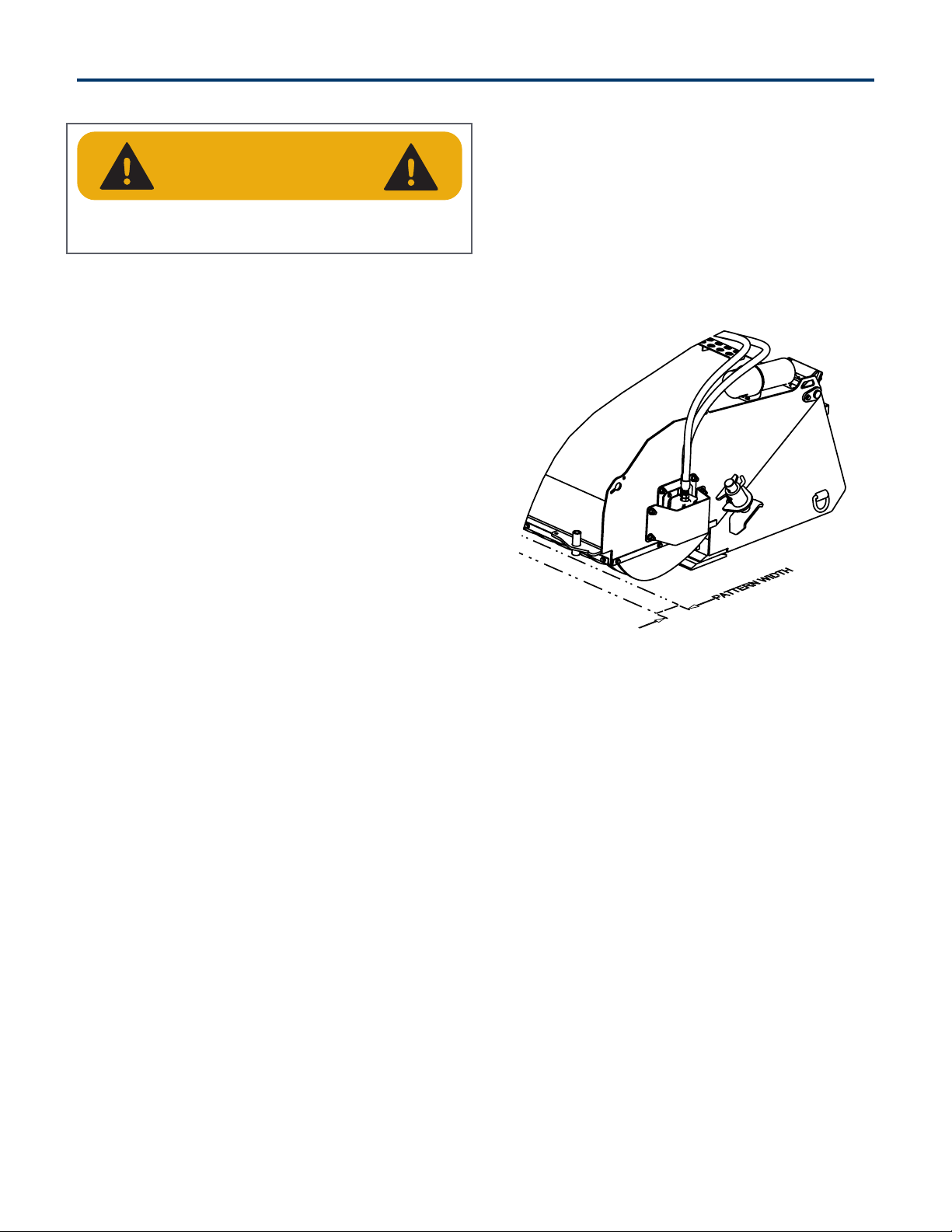
3.3 Checking and Adjusting
Broom Pattern
The brush pattern should be checked and adjusted
every 8 hours or daily. To check and adjust pattern:
1. Move the broom to a dusty flat surface.
2. With the loader at low throttle, start the broom
motor.
3. Slowly lower the broom until it is in the
operating position. (bolt-on edge is 1” o of
ground).
4. Keep the broom in this position for 10 seconds.
Do not move loader.
5. Raise broom, stop the broom motor, and move
the loader back several feet. Lower broom to
ground, set loader brake and exit loader.
6. Measure pattern width left by broom. Pattern
should be 2”–4” wide.
7. To adjust pattern, carefully prop up the broom
shroud assembly. Remove the two bent leg
pins.
8. Move the two stop pins to a dierent hole
location and replace the two bent pins. To
widen the pattern move the stop pins up; to
narrow the pattern move the stop pins down.
See Figure 3.
Figure 3
3. Maintenance
WARNING
The following precautions must be observed for
the safety of the operator and bystanders.

Blue Diamond® Attachments10
3.4 Broom Wafers
Removing Broom Wafers
See parts diagram for pictures.
1. Place broom on ground and perform
mandatory shutdown procedure (see section
1.3 Mandatory Safety Shutdown Procedure on
page 3).
2. Remove side rubber skirt retainers.
3. Remove motor guard hardware and motor
guard plate.
4. Remove bearing guard hardware and bearing
guard plate.
5. Remove motor plate to broom housing
hardware and remove motor subassembly.
6. Remove bearing plate to broom housing
hardware.
7. Using hoist, raise broom housing o of broom
core. Roll broom core away from bucket.
8. Remove end retainer from one broom
core
end
.
9. Remove wafers.
Replacing Broom Wafers
See parts diagram for pictures.
1. Place broom drum on end with one retaining
plate assembled. Place retaining plate on ground
.
2. Install a new wafer making sure wafer retention
pins are trapped on broom drum bar.
3. Install more wafers. Alternate steel and poly
wafers if using both types. The retention pins
on consecutive wafers should alternate 180°
and be trapped by opposite bars.
4. Install last wafer and install broom drum
retaining plate. Carefully lay the core on its side
.
5. Move core under broom housing and lower
housing on core.
6. Replace bearing plate and motor plate
hardware. Tighten hardware.
7. Replace motor and bearing guard plates and
hardware. Tighten hardware.
8. Reinstall rubber skirting and side skirting
retainers.
9. Tighten hardware.
3.5 Removing and Replacing
Motor
See parts diagram for pictures.
1. Place broom the ground and perform
mandatory shutdown procedure (see section
1.3 Mandatory Safety Shutdown Procedure on
page 3).
2. Remove left side rubber skirt retainer.
3. Remove and cap motor hoses.
4. Remove motor guard hardware and motor
guard plate.
5. Remove motor subassembly from broom
housing.
6. Remove coupler bolt and loosen coupler set
screw. Remove coupler from motor shaft.
7. Remove motor gasket plate hardware, gasket
plates, and gasket.
8. Remove motor can hardware and remove motor.
9. Reassemble in reverse order.
3.6 Removing and Replacing
Bearing
See parts diagram for pictures.
1. Place broom the ground and perform
mandatory shutdown procedure (see section
1.3 Mandatory Safety Shutdown Procedure on
page 3).
2. Remove right side rubber skirt retainer.
3. Remove bearing guard hardware and bearing
guard plate.
4. Remove bearing plate to broom housing
hardware.
5. Loosen bearing lock collar with a drift punch
and hammer. Counter clockwise loosens collar.
6. Remove bearing and bearing plate.
7. Remove bearing plate to bearing hardware to
remove bearing.
8. Reassemble in reverse order. To tighten
bearing lock collar, use hammer and drive
punch. Clockwise movement tightens collar.
3. Maintenance
11Blue Diamond® Attachments
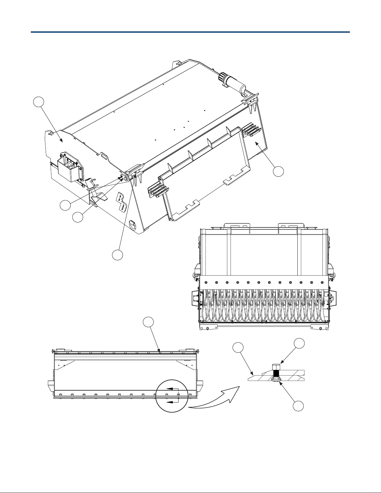
4. Parts
4.1 Main Parts Breakdown
2
5
4
3
1
9
8
6
7

Blue Diamond® Attachments12
ITEM PART NUMBER DESCRIPTION QTY 60”
316580
QTY 72”
316538
QTY 84”
316586
QTY 96”
316589
1
216370-60
Bucket Weldment - 60" 1 — — —
216380-60*
216370-72
Bucket Weldment - 72" — 1 — —
216380-72*
216370-84
Bucket Weldment - 84" — — 1 —
216380-84*
216370-96
Bucket Weldment - 96" — — — 1
216380-96*
2
216371-60
Hood Weldment - 60" 1 — — —
216381-60*
216371-72
Hood Weldment - 72" — 1 — —
216381-72*
216371-84
Hood Weldment - 84" — — 1 —
216381-84*
216371-96
Hood Weldment - 96" — — — 1
216381-96*
3 216465 Hood Pivot Pin 2 2 2 2
4 299426 3/8 x 1 1/4" Bolt 2 2 2 2
5
299016 Pivot Grease Fitting 2 2 2 2
297005*Pivot Grease Fitting 2 2 2 2
6
216560 Bolt-On Edge - 60" 1 — — —
216562 Bolt-On Edge - 72" — 1 — —
216564 Bolt-On Edge - 84" — — 1 —
216566 Bolt-On Edge - 96" — — — 1
7 216570 3/4 x 2" Plow Bolt 10 12 14 16
8 299657 3/4" Nylock Nut 10 12 14 16
9 216375 Black Push-In Rivets for 3/8" Hole 11 13 15 17
*For serial numbers 144361, 151397, 151398, 151839-151844, 153113
4.1 Main Parts Breakdown Cont’d
4. Parts

13Blue Diamond® Attachments
4. Parts
4.2 Main Hood Breakdown
8
20
4
54
11 2
3
6
7
109
1

Blue Diamond® Attachments14
ITEM PART NUMBER DESCRIPTION QTY 60”
316580
QTY 72”
316538
QTY 84”
316586
QTY 96”
316589
1
216371-60
Hood Weldment - 60" 1 — — —
216381-60*
216371-72
Hood Weldment - 72" — 1 — —
216381-72*
216371-84
Hood Weldment - 84" — — 1 —
216381-84*
216371-96
Hood Weldment - 96" — — — 1
216381-96*
2 216450 Side Skirt Retainer Plate 2 2 2 2
3 216451 Side Skirt 2 2 2 2
4
216452 Front Skirt Retainer Plate - 60" 2 2 2 2
216454 Front Skirt Retainer Plate - 72" 2 2 2 2
216456 Front Skirt Retainer Plate - 84" 2 2 2 2
216458 Front Skirt Retainer Plate - 96" 2 2 2 2
5
216453 Front Skirt - 60" 1 1 1 1
216455 Front Skirt - 72" 1 1 1 1
216457 Front Skirt - 84" 1 1 1 1
216459 Front Skirt - 96" 1 1 1 1
6 216462 Pivot Stop Pin 2 2 2 2
7 216573 Bent Pull Clevis Pin 2 2 2 2
8 299423 Hood bolts - 3/8 x 1" 7 7 7 7
9 299426 Skirt Bolt - 3/8 x 1.25" 12 12 14 14
10 299724 Skirt Washer 12 12 14 14
11 299625 Skirt nut - 3/8" Nylock 12 12 14 14
*For serial numbers 144361, 151397, 151398, 151839-151844, 153113
4.2 Main Hood Breakdown Cont’d
4. Parts

15Blue Diamond® Attachments
4. Parts
ITEM PART NUMBER DESCRIPTION QTY
1
216372 Cover - Square Bearing 1
216382*Cover - Round Bearing 1
2
216373 Bearing Mount Plate - Square Bearing 1
216383*Bearing Mount Plate - Round Bearing 1
3
216590 Bearing - Square 1
216479*Bearing - Round 1
4
109177 Bearing Nuts - Square Bearing - 5/8" Stover 4
299618*Bearing Nuts - Round Bearing - 1/2" Nylock 4
5
299432 Cover Bolts - Square Bearing - 1/2 x 1.5" 4
299439*Cover Bolts - Round Bearing - 1/2 x 1.75" 4
6
299440 Bearing Bolts - Square Bearing - 5/8 x 1.75" 4
299433-2.25*Bearing Bolts - Round Bearing - 1/2 x 2.25" 4
*For serial numbers 144361, 151397, 151398, 151839-151844, 153113
4.3 Bearing Mount Breakdown
5
1
6
3
2
4
Blue Diamond® Attachments16
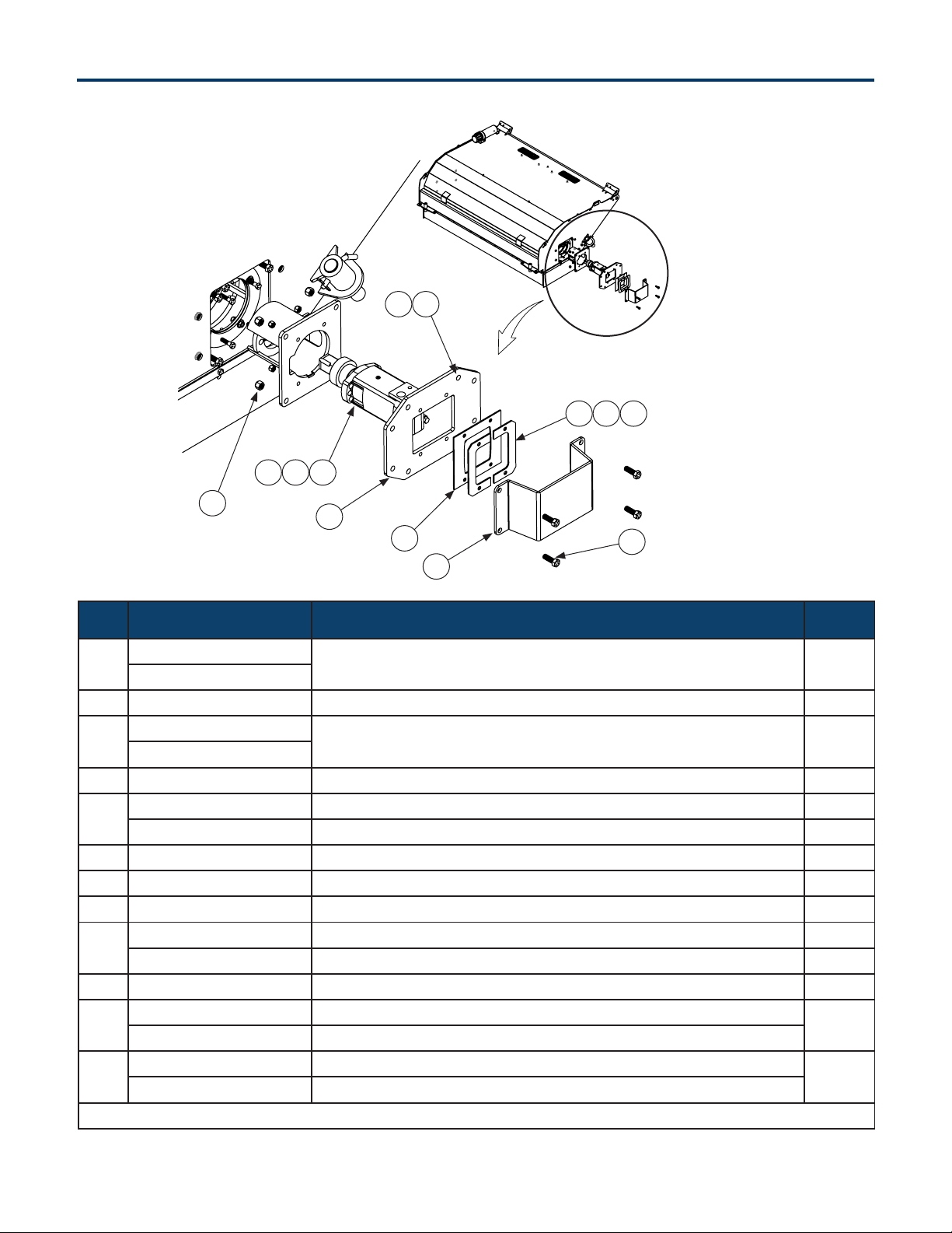
4. Parts
ITEM PART NUMBER DESCRIPTION QTY
1
216374
Left Side Motor Mount Plate 1
216384*
2 216377 Rubber Cover Retaining Plate 2
3
216372
Motor Cover 1
216382*
4 216376 Rubber Motor Cover 1
5
299432 Motor Cover Bolts - 1/2 x 1.5" 4
299439*Motor Cover Bolts - 1/2 x 1.75" 4
6 299618 Motor Mount Nut - 1/2" Nylock 2
7 299487 Rubber Motor Cover Bolts - 3/8 x 1.5" 4
8 299625 Rubber Motor Cover Nuts - 3/8" Nylock 4
9
299433 Motor Mount Bolt - 1/2 x 2" 2
299433-2.25*Motor Mount Bolt - 1/2 x 2.25" 2
10 See "Motor Assembly" Motor Assembly 1
11
299487 Motor Coupler Bolts - 3/8 x 1.5"
4
299439*Motor Coupler Bolts - 1/2 x 1.75"
12
299625 Motor Coupler Nuts - 3/8 Nylock
4
299618*Motor Coupler Nuts - 1/2 Nylock
*For serial numbers 144361, 151397, 151398, 151839-151844, 153113
4.4 Motor Mount Breakdown
12
1
11
72 8
910 6
12
4
3
5
17Blue Diamond® Attachments
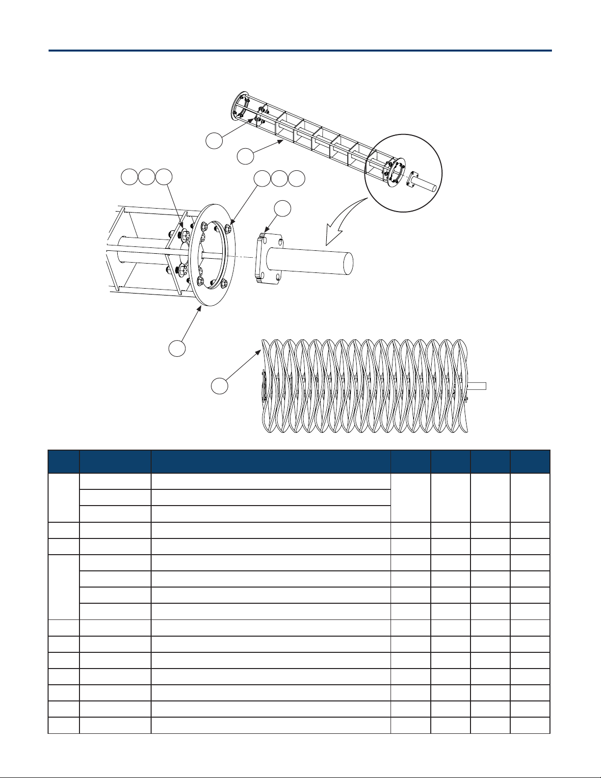
4. Parts
ITEM PART NUMBER DESCRIPTION QTY 60”
316580
QTY 72”
316538
QTY 84”
316586
QTY 96”
316589
1
216415 Wafer - Poly
31 37 43 49216410 Wafer - Steel
216417 Wafer - Poly/Steel
2 216478 Motor to Shaft Flange 1 1 1 1
3 216480 Drum to Bearing Shaft and Flange 1 1 1 1
4
216481 Drum Shaft - 60" 1 — — —
216482 Drum Shaft - 72" — 1 — —
216483 Drum Shaft - 84" — — 1 —
216484 Drum Shaft - 96" — — — 1
5 216378 Bristle Retaining Ring 1 1 1 1
6 299426 Retaining Ring Bolts - 3/8 x 1.25" 8 8 8 8
7 299625 Retaining Ring Nuts - 3/8" Nylock 8 8 8 8
8 299724 Retaining Ring Washers 16 16 16 16
9 299432 Flange Bolts - 1/2 x 1.5" 8 8 8 8
10 299618 Flange Nuts 1/2" Nylock 8 8 8 8
11 299732 Flange Washers 16 16 16 16
4.5 Drum Shaft Breakdown
2
4
5
3
6
11
1
7 8
109

Blue Diamond® Attachments18
4. Parts
ITEM PART NUMBER DESCRIPTION QTY
1
216421-2
Motor Shaft Coupler
1
216386*1
2
216425
Motor
1
216385*1
3
299724
Motor Coupler Washer
1
N/A*—
4 299447 Motor Coupler Bolt - 3/8 x 4" 1
*For serial numbers 144361, 151397, 151398, 151839-151844, 153113
4.6 Motor Assembly
2
1
3
4

19Blue Diamond® Attachments
4. Parts
4.7 Water Kit Breakdown
5
3
2
4
8 1
10
96
7
316571 60” Water Kit
316573 72” Water Kit
316576 84” Water Kit
316579 96” Water Kit

Blue Diamond® Attachments20
4. Parts
4.7 Water Kit Breakdown Cont’d
ITEM PART NUMBER DESCRIPTION QTY
1 216673 Pump Mount Bracket 1
2 216539 Pump Hood 1
3 216540 Pump 1
4 216650 Pub Tank 1
5 216655 Tank Strap 2
6
316580 60” Spray Bar Kit
1
316583 72” Spray Bar Kit
316586 84” Spray Bar Kit
316589 96” Spray Bar Kit
7 116555 Gutter Brush Assembly 1
8 299426 Hex Bolt-Grade 8-3/8-16 X 1 2
9 299625 Grade 8 Locknut 3/8-16 2
10 299725 Washer 3/8 2
NS 216688 1/2 Water Hose (per foot) 9
Other manuals for PICKUP BROOM 2 Series
1
This manual suits for next models
5
Table of contents
Popular Floor Machine manuals by other brands


Ghibli & Wirbel
Ghibli & Wirbel S-TEAM 6 V instruction manual

Kunzle & Tasin
Kunzle & Tasin NEW GOLIA PLUS S User & maintenance manual

Nilfisk-Advance
Nilfisk-Advance Clarke SA40 Instructions for use

Century 400
Century 400 Ninja 411-222MO operating instructions

Tennant
Tennant T3 Operator's manual

Powr-Flite
Powr-Flite PAS20BA Operators manual & parts lists
 operating instructions")


