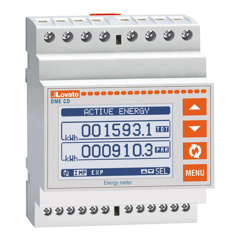
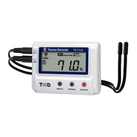
Blue Gizmo BG 38TC User manual

Professional temperature measuring instrument
Instruction manual
V1.3
Dual Channel
Thermocouple Datalogger
BG 38TC

Contents
General Notes ..................................................................................................................................................................................1
1. Safety Advice................................................................................................................................................................................3
2. Intended Purpose .........................................................................................................................................................................4
3. Products Description ....................................................................................................................................................................5
3.1 Display and control components ........................................................................................................................................5
3.2 Interface .............................................................................................................................................................................7
3.3 Power supply......................................................................................................................................................................7
4. Operation......................................................................................................................................................................................8
4.1 Ready to work ....................................................................................................................................................................8
4.2 Switching the instrument on/off ..........................................................................................................................................8
4.3 Backlight.............................................................................................................................................................................8
4.4 Multi-function button...........................................................................................................................................................9
4.5 Channel mode..................................................................................................................................................................10
4.6 Instrument settings........................................................................................................................................................... 11
4.7 Data settings ....................................................................................................................................................................12
4.8 Calibration the instrument ................................................................................................................................................14
4.9 Data recording(with data logging function) ......................................................................................................................17
5. Measuring...................................................................................................................................................................................19
6. Care and Maintenance ...............................................................................................................................................................21
7. Questions and Answers..............................................................................................................................................................22
8. Specifications .............................................................................................................................................................................23

1
General Notes
This chapter provides important advice on using this documentation.
This document contains information that is required to use this product safely and effectively. Please read
through the contents of this document carefully and be familiar with the operation of this product.
Button action
Short Press: Press the button and then raise it; you can hear a beep when pressing.
Press and hold: Press and hold the button for about 2s, raise it when hearing a beep.
When the corresponding function of the button is valid, there will be a beep. No sound means the current
function is not available or the button sound is turned off.

2
Identification
Representation
Meaning
Comments
‼
Note
Provide important tips and information.
✓
Condition
The conditions that must be met before performing an operation.
➢,1,2...
Objective
Indicate the objective that is to be achieved via the steps
described. The numbers are the order of the steps required to
achieve this objective, which must always be followed.
Button
Press/Hold the button.
—
Supplement
Additional instructions for certain operations or projects.
⚫
List
List some details or examples related to the project.
◆
Result
The result of performing some operations.
BUTTON

3
1.Safety Advice
This chapter provides general rules that must be followed and adhered to If the product is to be used safely.
Avoid personal injury/equipment damage
⚫Do not use the measuring instrument and probes to measure on or near live parts (especially
high-voltage electricity).
⚫Corrosive solvents can’t be measured with the probe unless it is a designated anti-corrosion probe.
Product safety/warranty claims
⚫Operate the instrument only within the range specified in the specifications.
⚫Always use the instrument properly and for its intended purpose.
⚫Do not place handles and cables in environments above 80℃ unless they are explicitly allowed to be
used at elevated temperatures. Temperatures given on the probes are only related to the sensor's
measuring range.
⚫The instrument can only be disassembled if it is explicitly stated in the documentation for maintenance
and repair purposes. Perform only the maintenance and repair work described in this document. Follow
the prescribed steps to perform maintenance and repair work. To be on the safe side,only the spare parts
from the original factory can be used.
Ensure correct disposal
⚫Take faulty rechargeable batteries/spent batteries to the collection points provided for them.
⚫Send the product back to the original factory at the end of its useful life. We ensure that it will be disposed
of in an environmentally friendly manner.

4
2.Intended Purpose
This chapter describes the areas of application for which the product is intended.
Use the product only for those applications for which it was designed. This instrument is a two channel
high-precision measuring instrument with calibration for temperature measurement.
Accurate Measurement: Whether it is a low temperature cold storage or a high temperature boiler,
flexible use multi-type probe will ensure accurate measurement over the whole range.
Safe and Reliable: Provide a safe and reliable measurement experience during the measurement
process.
High Scalability: Use standard thermocouple socket to connect probe of any shape.
Excellent Performance: Super large backlight display; temperature over-limit alarm; maximum /
minimum / average display;Large dot matrix LCD display more information.
Practical Accessories: soft protective cover, waterproof and oil resistant, IP52 protection level can be
achieved when connected to a temperature probe.
The product is designed for the following areas:
⚫Temperature standard instrument
⚫Scientific experiments
⚫Medical
⚫Food
⚫Chemical industry
⚫HVAC industry
The product should not be used in the following areas:
⚫Hazardous explosive areas
⚫High voltage areas
⚫Smelting industry

5
3.Products Description
This chapter provides an overview of components of the product and their functions.
3.1 Display and control components
Overview
LCD
Button
Probe Socket
Battery Compartment
USB Interface

6
Button Functions
Button
Functions
Multi-function button 1, the function will be displayed at the bottom left of the screen.
Switch instrument on; Switch instrument off (hold the button).
Switch display light on/off.
Multi-function button 2, the function will be displayed at the bottom right of the screen.
Switch type of probe.
Keep reading.
Display Max/Min/Avg value.
Switch unit of reading.
Important displays
Displays
Meaning
Alarm enable: Displayed when the alarm function is enabled, and the next icon is
combined to indicate the enabled channel.
、 、
Only channel 1 enable alarm, only channel 2 enable alarm, both channels enable
alarms.
、
High and low limit alarms: Display when the temperature exceeds the high or low
limit.
Auto shutdown: display when auto shutdown function is enabled.
Battery capacity: display with battery power.
Display when the instrument is connected to USB.
F1
F2
PROBE
HOLD
MAX/MIN/AVG
℃/℉

7
Display area division
Dividing the area is for quick positioning of the icons or readings you want to view.
3.2 Interface
⚫Probe Interface
—A plug-in measuring probe can be connected to the measuring instrument via the probe socket.
⚫USB Interface
—The instrument can be connected to a computer or other 5V USB powered device via a Micro USB
cable.
3.3 Power supply
⚫The instrument is powered by three 1.5V AAA or 1.5V rechargeable batteries under normal conditions.
USB interface can provide 5V voltage in emergencies. However, unstable USB power supply will result in
inaccurate measurement, so USB power supply is not recommended.
Statues Area
Main Screen Area
Indicating Area

8
4.Operation
This chapter describes the steps that have to be executed frequently when using the product.
4.1 Ready to work
⚫Remove the protective film from the display.
⚫Insert the battery/rechargeable battery into the battery compartment, observe the polarity of the battery.
⚫Insert the probe plug into the probe interface of the instrument.
4.2 Switching the instrument on/off
➢Switching the instrument on / view the version number and serial number
1. Press to turn on the instrument. The version number and serial number can be viewed on the
screen by pressing the before entering the measurement interface.
➢Switching the instrument off
1. Press and hold . Raise the button when you see “shut down”.
4.3 Backlight
➢Switching the backlight on/off
✓The instrument is switched on.
1. Press .
℃/℉

9
4.4 Multi-function button
⚫The instrument has two multi-function buttons: and . Their specific functions will be displayed in
the function description area!
Commonly used function of F1 button
Commonly used function of F2 button
Config
Enter the configuration interface.
Menu
Enter the menu interface.
Enter
Go to the next level option interface.
Exit
Enter configuration interface or menu
Set
Change the settings of the current option.
Interface.
Ok
Confirm changes to an option or value.
Back
Return to the previous interface or exit the
Yes
Perform an action.
Editing interface.
Edit
Edit a value.
No
Cancel an action.
F1
F2

10
4.5 Channel mode
⚫The instrument has two temperature measurement channels and four mode interfaces, which can be
used flexibly to meet different measurement needs. Four mode interfaces are as shown in the following
table:
Channel mode
Dual channel merge
mode
Single channel one
mode
Single channel two
mode
Dual channel
difference mode
Example
Feature
Both channels are
measured and
displayed
simultaneously.
Can view the
temperature curve of
channel 1 in the past
35 seconds.
Can view the
temperature curve of
channel 2 in the past
35 seconds.
Suitable for
measuring items
related to
temperature
differences.

11
⚫Single channel trend chart
‼The maximum temperature of the trend graph is set to be 105% of the maximum measured temperature over the
past 35 seconds. Therefore, the temperature values displayed on the screen may be outside the measurement
range, but is does not mean that the instrument can measure temperatures outside this range. The same is true
for the lowest temperature of the trend graph.
4.6 Instrument settings
➢To open configuration mode
✓The instrument is turned on and the function description area displays: .
1. Press (Config). Enter the configuration mode.
‼The configuration interface is as shown on the right. You can press /to move
the cursor.
‼The settings related to instrument properties are located in the configuration interface.
‼You can exit configuration mode at any time by press (Exit). The changed settings
will be saved when you exit the configuration interface.
F1
F2
Maximum Temperature
Minimum Temperature
High Limit Alarm Value
Low Limit Alarm Value
Timeline(negative sign indicates
this is the past time in seconds)
Temperature Curve

12
➢To set channel mode
✓Configuration mode is opened, move the cursor to “Channel Mode” and press (Enter).
1. Use / to select the desired mode, press (Ok)to confirm the selection or press
(Back)to exit directly.
➢To set button sound
✓Configuration mode is opened, move the cursor to “Sound”.
1. Press (Set)to switch settings.
➢To set the automatic shut-down.
✓Configuration mode is opened, move the cursor to“Auto off”.
‼When the automatic shutdown function is turn on, the instrument will automatically turn off if no button is pressed
within 10 minutes.
1. Press (Set)to switch settings.
➢To restore the factory configuration
✓Configuration mode is opened, move the cursor to “Recovery” and press (Enter)to enter, waiting for 5
seconds.
1. Press (Yes)to reset to the factory settings. Press the (No)button to return to the
configuration mode.
4.7 Data settings
➢To open menu interface
✓The instrument is turned on and the function description area displays: .
1. Press (Menu). Enter the menu interface.
‼The menu interface will vary according to the channel mode, as shown in the table below.
F1
F1
F2
F1
F1
F1
F1
F2
F2

13
‼You can press /to switch between different menu options. If there is a triangle icon at the far right
of the cursor, there is a sub-option. Press / to switch the sub-option.
‼The options related to the measurement data are in the menu interface.
‼You can exit menu mode at any time by pressing the (Exit). The changed settings will be saved when you
exit the menu.
➢To set the temperature alarm high limit
✓Open the instrument and enter the menu interface.
1. Move the cursor to “High Limit-CH1” or “High Limit-CH2” and press (Edit)to set the
temperature high limit alarm value of the channel.(In dual channel merge mode, the option for
channel two is collapsed in the sub-option. You need to press the button first.)
➢To set the temperature alarm low limit
✓Open the instrument and enter the menu interface.
1. Move the cursor to “Low Limit-CH1” or “Low Limit-CH2” and press (Edit)to set the temperature
low limit alarm value of the channel. (In dual channel merge mode, the option for channel two is
collapsed in the sub-option. You need to press the button first.)
➢To set temperature alarm switch
Channel
mode
Dual channel merge mode
Single channel
one mode
Single channel
two mode
Dual channel
difference
mode
Option one
High Limit-CH1
High Limit-CH2
High Limit-CH1
High Limit-CH2
Difference Limit
Option two
Low Limit-CH1
Low Limit-CH2
Low Limit-CH1
Low Limit-CH2
Diff-Alarm
Option three
Alarm-CH1
Alarm-CH2
Alarm-CH1
Alarm-CH2
Calibration
Option four
Calibration
Calibration
Calibration
F2
F1
F1

14
✓Open the instrument and enter the menu interface.
‼The status of the alarm enable will be displayed directly on the option, and “Beep” means that the alarm way is
sound by the buzzer.
1. Move the cursor to “Alarm-CH1” or “Alarm-CH2” and press (Set)to turn the channel’s
temperature alarm on or off. (In dual channel merge mode, the option for channel two is collapsed
in the sub-option. You need to press the button first.)
➢To set temperature difference alarm value
✓In dual channel difference mode, enter the menu interface.
1. Move the cursor to “Difference Limit”,Press (Edit)to set the temperature difference alarm
value.
➢To set the temperature difference alarm switch
✓In dual channel difference mode, enter the menu interface.
!! When the absolute value of the temperature difference between the two channels is greater than the temperature
difference alarm value, the temperature difference alarm is triggered.
1. Move the cursor to “Diff-Alarm” and press (Set)to turn the temperature difference alarm on or
off.
4.8 Calibration the instrument
➢To open the calibration mode
✓Open the instrument and enter the menu interface.
‼This instrument supports three types probe K,T,J,and the three probes can be calibrated separately, and all
probes calibration operation are the same. Each probe supports 10 calibration points. Calibration will directly
affect the measurement data, please ensure that the calibration value is the result of correct measurement
by a high-precision instrument.
1. Move the cursor to “Calibration” and press (Enter).
F1
F1
F1
F1

15
➢Start calibration/view total calibration points
✓Open the calibration mode and enter the “select probe type” interface.
‼In this interface, you can see the number of existing calibration points directly after the probe type. For example, if
the K type probe has 2 calibration points, it will display “Type-K: 2 point”.
‼All probes calibration operation are the same, so the following operation takes the calibration of K type probe as an
example .
1. Move the cursor to “Type-K” and press (Enter)to start calibrating the Type-K probe.
➢Delete all calibration points for a certain type of probe
✓Open the calibration mode and enter the “select probe type” interface.
‼All probes calibration operation are the same, so the following operation takes the calibration of K type probe as an
example.
1. Move the cursor to “Type-K”, press the button, change the option to “Type-K:delete”, then
press the (Yes)button to delete all K calibration points(the calibration points of other probe will
not be delete).
➢Add a calibration point
✓Open the calibration mode and select the type of probe to calibrate on “Select probe type” interface to enter the
“Edit point” interface.
‼After each calibration point, the temperature value before calibration is displayed, such as “Data 1:-100.00℃”,
which means that the pre-calibration temperature value of the first calibration point is -100.00℃. Each time a
calibration point is added, it is automatically sorted according to the temperature value before calibration.
1. Move the cursor to “New data”, press (Add)to enter the calibration point editing mode. The
calibration point editing interface is as shown in the figure below called “Calibration Point Editing
Interface”.
2. Press / to move the cursor and press / to increase or decrease the number at the
cursor position. Enter the temperature value before calibration in the “Before” filed and the
F1
F1
F1

16
temperature value after calibration in the “After” filed.
3. Press (Save)to save the calibration point data,and press (Back)to return to the previous
interface.
‼When the calibration is in effect, the affected channel number is displayed in reverse color. As shown in the figure
below, “Before Calibration” and “After Calibration”.
Calibration Point Editing Interface Before Calibration After Calibration
➢ Edit a calibration point
✓Open the calibration mode and select the type of probe to calibrate on the “Select probe type” interface, then enter
into “Edit point” interface.
1. If the calibration point is entered incorrectly, for example, the second calibration point is wrong, you
can move the cursor to second calibration point, then press (Yes) button enter into edit mode
to modify the calibration data.
➢Remove a calibration point
✓Open the calibration mode and select the type of probe to calibrate on the “select probe type” interface to enter
into “Edit point” interface.
1. If a calibration point is not needed, for example, the second calibration point, you can move the
cursor to the second calibration point, then press to make the option change to “Remove data
2”, then press the (Yes)to remove the calibration data.
F1
F2
F1
F1

17
4.9 Data recording(with data logging function)
➢ Enter record mode
✓Turn on the instrument and enter the menu interface.
‼This product supports 20000 data points.
1. Move the cursor to "Logging" and press (Enter).
➢Start/Abandon recording
✓Enter record mode and enter the Logging interface.
‼The internal storage will be cleared at the beginning of the recording, so the last record data will be cleared.
Automatic shutdown function will be disabled.
‼During the recording process, (the recorded data points, the icon will be displayed on the screen).
1. Move the cursor to "Start Logging" and press (Enter)to confirm. Then press (Start)
to start recording, or press (Exit) to abandon recording.
➢Stop recording/Saving results
‼The recorded data will be saved and generate file automatically after stop recording. And the files can be viewed
on a computer.
1. The methods to stop recording:
a. Press (Stop)to stop recording.
b. Recording stops when battery power is insufficient.
c. Recording stops when the battery is loose.
d. Recording stops after turning off the device.
➢View record information
✓Enter record mode and enter the Logging interface.
1. Move the cursor to "View" and press , Press / to switch display contents.
F1
F1
F1
F2
F1
F1

18
➢Regenerate file
✓When the record file is corrupted, it can be used to recover the file. Set the file format before generating files in
other formats. The old file will be cleared when generate a new file. Please make a backup.
1. Move the cursor to "Regenerate File" and press (Ok)to generate the file again.
➢Enter setting mode
✓Turn on record mode and enter the Logging interface.
1. Move the cursor to "Settings" and press "Set" to enter the setting interface.
➢Time setting
➢Open the record mode and enter the Log Setting interface
‼Time must be reset before recording.
1. Move the cursor to "Set Time", and press "Set" to enter the time setting interface.
2. Press / to select the option, press / to modify the value of the option, press
(Ok)to confirm the setting.
➢Sampling rate setting
✓Enter the record mode and enter the Log Setting interface.
‼Sampling rate can be set from 1 second to 86399 seconds.
1. Move the cursor to "Set Sample Rate", and press "Set" to enter the interface of sampling
rate setting.
2. Press / to select the option,/ to modify the value of the option, (Ok)
to save the sampling rate.
➢Set file format
✓Enter the record mode and enter the Log Setting interface.
1. Move the cursor to "Set File Format", and press to enter the interface of file format setting.
2. Press / to select the file format. Press (Ok)to save the file format.
F1
F1
F1
F1
F1
F1
F1
F1
Table of contents
