LOVATO ELECTRIC DME CD User manual

Dok: I311PLGB1210_DMECD 14/12/2010 s. 1 / 21
PL
DME CD DME CD
Rejestrator danych Data concentrator
INSTRUKCJA OBSŁUGI INSTRUCTIONS MANUAL
●Przed pracami serwisowymi, należy odłączyćwszystkie napięcia od wejść
pomiarowych i zasilania pomocniczego oraz zewrzećzaciski przekładnika
prądowego.
●Produkty zaprezentowane w poniższym dokumencie mogązostaćzmienione
lub ulepszone bez konieczności wcześniejszego informowania o tym.
●Dane techniczne oraz opisy oddająw jak najdokładniejszy sposób posiadaną
przez nas wiedzę, jednak nie bierzemy odpowiedzialności za ewentualne błędy,
braki oraz sytuacje awaryjne.
●W układzie należy zamontowaćrozłącznik (wyłącznik), który musi znajdować
sięniedaleko urządzenia i byćłatwo dostępny dla operatora. Musi spełniaćwymogi
następujących norm: IEC/ EN 61010-1 § 6.12.2.1.
●Należy umieścićurządzenie w obudowie lub szafie o minimalnym stopniu ochrony
IP40.
●Należy czyścićurządzenie delikatnąsuchąszmatką, nie należy używaćśrodków
ściernych, płynnych detergentów lub rozpuszczalników.
●Before any maintenance operation on the device, remove all the voltages from
measuring and supply inputs and short-circuit the CT input terminals.
●Products illustrated herein are subject to alteration and changes without prior
notice.
●Technical data and descriptions in the documentation are accurate, to the best
of our knowledge, but no liabilities for errors, omissions or contingencies arising
there from are accepted.
●A circuit breaker must be included in the electrical installation of the building. It
must be installed close by the equipment and within easy reach of the operator.
It must be marked as the disconnecting device of the equipment:
IEC /EN 61010-1 § 6.12.2.1.
●Fit the instrument in an enclosure or cabinet with minimum IP40 degree
protection.
●Clean the instrument with a soft dry cloth; do not use abrasives, liquid
detergents or solvents.
Spis treści
Strona
Wprowadzenie 2
Opis 2
Główne funkcje 2
Funkcje przycisków 2
Funkcje rejestratora danych 3
Funkcja pochodne
j
4
Funkcje matematyczne 4
Wyświetlanie pomiarów 4
Tabela wyświetlanych stron 5
Strona licznika godzin 6
Strona wykresów trendów 6
Menu główne 7
Hasło dostępu 7
Możliwość rozbudowy 8
Dodatkowe źródła 8
Kanały komunikacji 9
Wejścia, wyjścia, wewnętrzne zmienne
9
Progi limitów 10
Logika Boole’a 10
Zmienne kontrolowane zdalnie 11
A
larmy 11
Taryfy 12
Ustawianie parametrów 12
Tabela parametrów 13
Menu komend 18
Dane techniczne 19
Układ zacisków 19
Wymiary mechaniczne 19
Schematy połączeń20
Index
Page
Introduction
2
Description
2
Main functions
2
Keyboard functions
2
Data concentrator functions
3
Derivative function
4
Mathematical functions
4
Measurement viewing
4
Table of display pages
5
Hour counters page
6
Trend graph
page
6
Main menu
7
Password access
7
Expandability
8
A
dditional resources
8
Communication channels
9
Inputs, outputs, internal variables 9
Limit thresholds
10
Boolean logic
10
Remote-controlled variables
11
A
larms
11
Tariffs
12
Setting of parameters (setup) 12
Table of parameters
13
Commands menu
18
Technical characteristics
19
Terminal arrangement
19
Mechanical dimensions
19
Wiring diagrams 20
I311 PL GB 1210
UWAGA!
●Należy dokładnie zapoznaćsięz poniższąinstrukcjąprzed
instalacjąlub używaniem urządzenia.
●By uniknąć uszkodzeńi zagrożenia życia urządzenia
te powinny byćinstalowane przez wykwalifikowany personel,
i w zgodzie z odpowiednimi przepisami.
WARNING!
Carefully read the manual before the installation or use.
This equipment is to be installed by qualified personnel,
complying to current standards, to avoid damages or safety
hazards.

Dok: I311PLGB1210_DMECD 14/12/2010 s. 2 / 21
Wprowadzenie
Rejestrator danych DMECD jest urządzeniem, które zwiększa potencjał
zastosowania liczników energii serii DME, to jest umożliwia zbieranie
danych i przesyłanie ich do systemu zdalnej kontroli. DMECD, dzięki
swojej elastyczności zastosowania, niespotykanej w innych urządzeniach,
może byćrównieżużywany, jako urządzenie niezależne służące
do zliczania zużycia energii z liczników różnego typu czy teżzliczania ilości
operacji urządzeńprodukcyjnych itp.. Wyświetlacz graficzny LCD zapewnia
przyjazny dla użytkownika interfejs. Port optyczny podczerwieni umożliwia
rozbudowęfunkcjonalności, przy zastosowaniu modułów EXM…,
o różnego typu komunikacjęi dodatkowe kanały wejść.
Introduction
The DMECD data concentrator is a device that extends the potential of
DME energy meters family, providing a data collector function together
with an interface to remote supervision systems.
The DMECD can be used also in several applications as a stand-alone
product, to measure the consumption of counters of various types, to
measure the production of machinery etc, thanks to its extreme
configuration flexibility that has no equal in this kind of devices. The LCD
graphic display offers a user-friendly interface. The Infra-red optical port
allows the expansion of the unit by means of the wide range of EXM…
expansion modules, allowing to support various types of communication
and to connect additional input channels.
Opis
Obudowa modułowa 4U (72mm) na szynęDIN.
Graficzny wyświetlacz LCD, 128x80 pikseli, z podświetleniem,
4 poziomy szarości.
4 przyciski funkcyjne do ustawieńi wizualizacji.
Szybka i prosta nawigacja po menu.
Teksty pomiarów, parametrów i informacji w 5 językach.
8 wbudowanych wejść (maks. 14 z modułami rozszerzeń).
Wejścia jednostki podzielone sąna 4 pary, wzajemnie od siebie
izolowane.
1 wejście pomocnicze AC, do wyboru taryfy.
Wbudowany port RS-485.
Optyczny interfejs do podłączenia modułów rozszerzeńtypu EXM…
(maksymalnie 3 sztuki).
Description
Modular DIN-rail housing, 4U (72mm wide).
Graphic LCD display, 128x80 pixels, white backlight, 4 grey levels.
Membrane keyboard with 4 keys for visualization and setting.
Easy and fast navigation.
Texts for measures, setup and messages in 5 languages.
8 built-in contact input channels (max 14 with expansion).
Built-in inputs organized as 4 couples insulated between them.
1 auxiliary AC input channel for selecting the tariff.
Integrated RS-485 interface.
Optical interface for a max of 3 expansion modules series EXM....
Główne funkcje
Zarządzanie w pełni programowalnymi 14 licznikami (alfanumeryczny
opis, jednostki pomiarów, współczynniki naliczania).
Możliwość kasowania liczników częściowych.
Dwukierunkowe zarządzanie licznikami (góra / dół).
Zarządzanie pochodnązliczania (wskazania mocy średniej, prędkości
produkcji, itp.).
Wizualizacja graficzna trendów pochodnej zliczania.
Zarządzanie 4 taryfami.
Programowalne funkcje WEJ/WYJ.
Zarządzanie alarmami po przekroczeniu progów.
Programowalna kalkulacja funkcjami matematycznymi
(suma z liczników, relacjępomiędzy wartościami itp.)
Main functions
Management of max 14 completely programmable meters
(alphanumerical description, unit of measure, count increase
coefficients).
Resettable partial meters.
Two-way (up / down) meter management.
Count derivative management (indication of mean power, production
speed, etc.).
Display of count derivative trend graphs.
Management of max 4 tariffs.
Programmable I/O functions.
Alarm management on exceeding thresholds.
Programmable mathematical calculation functions (sums of meters,
relations between quantities, etc.)
Funkcje przycisków
Przyciski ▲i▼-Służą do przewijania wyświetlanych stron,
by dokonywaćmożliwego wyboru i do modyfikacji ustawień
(zwiększanie/zmniejszanie).
Przycisk - Służy do przechodzenia pomiędzy podstronami,
do potwierdzania dokonanego wyboru i do przełączania pomiędzy trybami
wizualizacji.
Przycisk MENU –Służy do wchodzenia lub wychodzenia z wizualizacji
i menu ustawień.
Keyboard
functions
▲and ▼keys – Used to scroll display pages, to select among possible
choices, and to modify settings (increment-decrement).
key – Used to rotate through sub-pages, to confirm a choice, to
switch between visualization modes.
MENU key – Used to enter or exit from visualization and setting menus.

Dok: I311PLGB1210_DMECD 14/12/2010 s. 3 / 21
Funkcje rejestratora danych
Rejestrator DMECD może zarządzaćmaksymalnie 16 licznikami,
określanych CNT01..16, każdy z licznikiem całkowitym (TOT)
i częściowym (PAR), oba z możliwościąkasowania.
Liczniki sąw pełni programowalne. Dla każdego licznika istnieje
możliwość zdefiniowania następującej charakterystyki:
Włączanie licznika ogólnego
Opis alfanumeryczny licznika
Opis alfanumeryczny jednostki pomiarowej
Sygnałzwiększający stan licznika (źródło)
Sygnałzmniejszający stan licznika (źródło)
Współczynnik zwiększania/zmniejszania
Sygnałkasowania licznika częściowego
Sygnałkasowania licznika całkowitego
Włączanie pochodnej pomiaru
Jednostki pochodnej pomiaru
Włączanie licznika ogólnego
Włącza licznik i umożliwia zliczanie.
Opis alfanumeryczny licznika
Dowolny ciąg znaków (maksymalnie 16), który opisuje licznik. Opis
ten będzie wyświetlany, jako tytułstrony odnoszącej siędo licznika.
Na przykład: Pomieszczenie kompresora
Opis alfanumeryczny jednostki pomiaru
Dowolny ciąg znaków (maksymalnie 6), który opisuje jednostkę
pomiaru licznika.
Na przykład: kWh
Sygnałzwiększający stan licznika (źródło)
Definiuje sygnał, który powoduje zwiększanie stanu licznika. Normalnie
jest to sygnałz wejść cyfrowych DMECD lub modułu rozszerzeń,
ale może to byćrównieżwynik logiki Boole’a pochodzącej z innych
zmiennych. Definicji źródła sygnału odbywa sięprzez określenie typu
sygnału (wejście, zmienna Boole’a, zmienna zdalna, próg, itp.)
i określenia kanału (kolejny numer typu sygnału).
Przykład: INP 2 – Aktywacja wejścia INP2 zwiększa stan licznika
wartościązdefiniowaną, jako współczynnik zwiększania.
Sygnałzmniejszający stan licznika (źródło)
Sygnałopcjonalny. Opis jak powyżej, tylko dotyczy zmniejszenia stanu
licznika.
Przykład: INP 3 – Aktywacja wejścia INP3 zmniejsza stan licznika
wartościązdefiniowaną, jako współczynnik zmniejszania.
Współczynnik zwiększania/zmniejszania
Użytkownik ma możliwość zdefiniowania współczynnika zmiany ilości
zliczanych impulsów na informacjęwyświetlanąna ekranie. Tęfunkcję
określa mnożnik i współczynnik ułamkowy.
Jeśli licznik nie ma współczynnika ułamkowego to wyświetlane będą
tylko liczby całkowite. W innym przypadku na ekranie pokazane będą
wartości z dwoma cyframi po przecinku.
Przykład: po ustawieniu mnożnika k = 3, każdy odczytany impuls
będzie zwiększałwyświetlany pomiar razy 3. Jeśli zaprogramujemy
współczynnik ułamkowy = 10, to wyświetlany pomiar będzie
zwiększany po zliczeniu 10 impulsów podanych na wejście. Dzięki
kombinacji mnożnika i współczynnika ułamkowego można uzyskać
jakikolwiek stosunek zmiany.
Sygnałkasowania licznika częściowego
Sygnałopcjonalny, który po pojawieniu siękasuje licznik częściowy.
Równieżw tym przypadku definiuje siętyp sygnału i kolejny numer.
Przykład: REM 1 – Licznik jest kasowany po pojawieniu sięzmiennej
zdalnej REM1 przesłanej przez protokoły komunikacyjne.
Sygnałkasowania licznika całkowitego
Opis jak powyżej, tylko dotyczy licznika całkowitego.
Functions of the data concentrator
The DMECD can manage up to a maximum of 16 meters,
called CNT01..16, each with a total (TOT) and partial count
(PAR) both resettable.
The meters are completely programmable. For each meter it
is possible to define the following characteristics:
general meter enable
meter alphanumerical description
meter alphanumerical unit of measure
count increase signal (source)
count decrease signal (source)
increase/decrease coefficient
partial meter reset signal
total meter reset signal
derivative measure enable
unit of derivative measure
General meter enable
This enables viewing and updating the meter.
Meter alphanumerical description
Free string with a max length of 16 characters that describes
the meter. This string will be shown as the title of the page that
views the meter.
Example: Compressor room
Meter alphanumerical unit of measure
Free string with a max length of 6 characters that describes
the meter unit of measure.
Example: kWh
Count increase signal (source)
This defines the signal that causes the count increase.
Normally it is one of the digital inputs of the DMECD or of the
expansion modules, but it could also be a Boolean
combination or other variable. The definition of the input
source is done defining the type of signal (input, Boolean
variable, remote variable, threshold, etc) and indicating which
channel (progressive number of type of signal).
Example: INP 2 – Activating input INP2 the meter is increased
by the value defined by the increase coefficient.
Count decrease signal (source)
Optional signal. The same may be said as for the previous
point, referring to the count decrease.
Example: INP 3 – Activating input INP3 the meter is decreased
by the value defined by the decrease coefficient.
Increase/decrease coefficient
A conversion coefficient can be defined between the number
of pulses counted and the measure shown on the display. This
function is obtained specifying a multiplicative and a fractional
coefficient. If the meter has no fractional coefficient, then it will
be viewed only with whole numbers. Otherwise two decimal
digits will be shown.
Example: setting multiplicative k = 3, for each pulse read the
value shown on the display will be increased by 3. Conversely
if a fractional coefficient = 10 is programmed, the measure
viewed will be increased only after 10 pulses applied at the
input. With the combination of multiplicative and fractional k it
is possible to obtain any conversion ratio.
Partial meter reset signal
Optional signal, which, when activated, resets the partial
meter. In this case too, it is defined specifying the type of
signal and progressive number.
Example: REM 1 – The partial meter is reset activating the
remote variable REM1 from communication protocol.
Total meter reset signal
The same may be said as for the previous point, referring to
the total meter.

Dok: I311PLGB1210_DMECD 14/12/2010 s. 4 / 21
Włączanie pochodnej pomiaru
Jeśli jest to wymagane to dla każdego licznika istnieje możliwość
wyświetlenia wskaźnika prędkości zmiany zliczania (pochodna).
Ta funkcja, na przykład, w klasycznym przypadku wskazania ilości
zużytej energii (kWh), umożliwia wskazanie aktualnej mocy średniej
pobieranej przez obciążenie (kW).
Jednostka pochodnej pomiaru
Dowolny ciąg znaków (maksymalnie 6), który opisuje jednostkę
pochodnej pomiaru.
Na przykład: kW
Uwaga:
Przy ustawieniach domyślnych rejestrator DMECD jest ustawiony
na odczyt impulsów zużycia energii pochodzących z wbudowanych
wyjść statycznych liczników energii serii DME.
Domyślnie liczniki energii DME wysyłająimpuls dla każdej 0.1kWh
(10 impulsów na kWh). Z tego powodu domyślne ustawienia
rejestratora danych DMECD zawierają:
oWspółczynnik zwiększania stanu licznika 0.1 (dzielnik 10)
oJednostka pomiaru licznika kWh
Równieżw odniesieniu do wyświetlanej pochodnej (moc czynna)
ustawienia domyślne umożliwiająodpowiednie wskazanie wyrażone
w kW.
Funkcja pochodnej
Zadaniem funkcji pochodnej jest umożliwienie wyświetlania
prędkości zwiększania stanu licznika.
W typowej aplikacji rejestrator DMECD w połączeniu z licznikiem
energii, przekłada pochodnąpobranej energii (kWh) na moc
wymaganąw danym momencie przez obciążenie (kW).
Kiedy urządzenie wykorzystywane jest w innej aplikacji (na przykład
do zliczania ilości sztuk wykonanych przez maszynę) pochodna
wskaże prędkość produkcji.
Dane pochodnej zliczania kalkulowane sąna podstawie średniej
z kilku ostatnich minut, za ustawiony okres kalkulacji. Przy włączeniu
pomiaru pochodnej należy ustawićten czas kalkulacji.
Jeśli wymagane jest zliczanie z częsta aktualizacjąto czas kalkulacji
musi byćustawiony na niewielkąwartość oraz należy ustawić
generator impulsów tak by emitowałimpulsy jak najczęściej.
Kiedy licznik jest powiązany z pomiarem pochodnej to istnieje
możliwość wyświetlenia wykresu, w funkcji czasu, poziomu poboru
(jeśli energia zliczana jest przez licznik DME)
lub prędkości produkcji (aplikacja ze zliczaniem ilości sztuk).
Stosunek pomiędzy jednostkąpomiaru licznika a jednostkąpomiaru
pochodnej, obie sądowolnie programowalne, wymaga ustawienia
matematycznej zależności występującej między nimi, którąmożna
zaprogramowaćprzy użyciu mnożnika i dzielnika pochodnej
w ustawieniach parametrów. Kalkulacja przebiega z uwzględnieniem
jednostek pomiaru i czasu wyliczenia pochodnej, który określony jest
w minutach.
Przykład 1 – Licznik energii: licznik w kWh, pochodna w kW – ich
stosunek wyrażony w minutach wynosi 60. Mnożnik = 60, dzielnik = 1.
Przykład 2 – Produkcja tkaniny: licznik w metrach, prędkość produkcji
w m/s - ich stosunek wyrażony w minutach 1 / 60, gdzie mnożnik = 1,
dzielnik = 60.
Funkcje matematyczne
Rejestrator DMECD umożliwia połączenie rożnych liczników
w zależności matematycznej w celu uzyskania dodatkowych
pomiarów.
Klasycznym przykładem jest, gdy w aplikacji posiadamy kilka
oddzielnych liczników a rejestrator danych powinien, autonomicznie,
wyliczyćwartość całkowitą(suma liczników).
Dla tej funkcji dostępnych jest 16 zmiennych matematycznych.
Każda z nich jest rezultatem działania matematycznego pomiędzy
dwoma zmiennymi i stała (opcja).
Dwie zmienne i stała (operand) mogązostaćpołączone ze sobą
Derivative measure enable
If required, for each count it is possible to have the indication
of the count change speed (derivative).
For example in the classical case of indication of the quantity
of energy consumed (kWh), this function makes it possible to
also have an indication of the mean power absorbed at
present by the load (kW).
Derivative unit of measure
Free string with a max length of 6 characters that describes
the derivative count unit of measure.
Example: kW
Note:
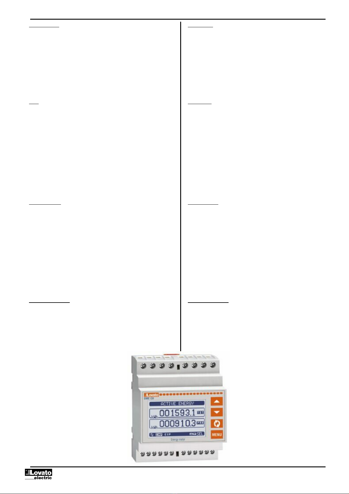
With the default settings, the DMECD is already set for
reading the energy count pulses leading from the built-in
static output in the devices of the DME series.
By default, the DME Energy meters emit a pulse every 0.1
kWh (10 pulses per kWh). For this reason, the default
settings of the DMECD include:
oMeter increase coefficient 0.1 (divisor 10)
oMeter unit of measure kWh
Also with regard to viewing the derivative (active power) the
default settings make it possible to have the correct
indication expressed in kW.
Derivative function
The purpose of the derivative function is to view the meter
increase speed.
In the typical application of the DMECD combined with an
energy meter, the derivative of the energy accumulated
(kWh) translates into the mean power required by the load in
a given moment (kW).
When the instrument is used in other applications (for
example counting pieces produced by a machine) the
derivative will give an indication of the production speed.
The count derivative datum is calculated referring to the
mean of the last minutes, with a period equivalent to the
calculation time set. To enable measurement of the
derivative, this time must be specified.
If metering is needed with frequent updating, the calculation
time must be set to a low value and the pulse generator
must be programmed to emit frequent pulses.
When a meter has associated the measure of the derivative,
it is also possible to have a graph of the time trend of
consumption levels (if the energy is metered for example by
a DME) or of the production speed (for the piece counter
application).
The relation between the unit of measure of the meter and
the unit of measure of the derivative, which are both free,
makes the mathematical setting of their ratio necessary,
which is done with the derivative multiplier and divisor
parameters. These are calculated taking into consideration
the units of measure and the fact that the derivative
calculation time is set in minutes.
Example 1 – Energy meter: Meter in kWh, derivative in kW –
their ratio, expressed in minutes is 60. Multiplier=60, divisor=1.
Example 2 – Production of fabric: Counter in metres,
production speed in m/s. their ratio, expressed in minutes, and
1 / 60 therefore multiplier = 1, divisor = 60.
Mathematical functions
With the DMECD it is possible to put the various meters into
mathematical relation to obtain additional measures.
A classical example is when there are different separate
energy meters and the data concentrator is required to
autonomously calculate the total (sum of the meters).
For these functions a total of 16 mathematical variables are
available. Each of them is the result of a mathematical
operation between two variables and of a constant
(optional).
The two variables and the constant (operands) can be put

Dok: I311PLGB1210_DMECD 14/12/2010 s. 5 / 21
przy użyciu funkcji matematycznych (+, - ,x ,/ ).
Zmienne matematyczne, następnie, mogązostaćwykorzystane, jako
operandy do wyliczenia nowych zmiennych matematycznych
(akumulacja).
Użytkownik może zdecydowaćczy zmienne matematyczne mająbyć
wyświetlane na ekranie rejestratora czy teżnie.
Przykład: Jeśli chcemy wyliczyćMAT1 = suma licznika CNT1 i CNT2:
.
Operand 1 Operato
r
1 Operand
2
Operator 2
Stała
CNT1 + CNT
2
+ 0
into relation with one another with different mathematical
operators (+, - ,x ,/ ).
The mathematical variables can then in turn be used as
operands to calculate new mathematical variables
(accumulation).
The user can then decide whether the mathematical
variables are to be viewed on the display or not.
Example: Wanting to calculate MAT1= sum between meter
CNT1 and CNT2:
.
Operand 1
Operator 1
Operand
2
Operator 2 Constant
CNT1
+
CNT
2
+ 0
Wyświetlanie pomiarów
Przyciski ▲i ▼pozwalająna przemieszczanie siępomiędzy
stronami wizualizacji odczytów, jedna po drugiej. Zawartość
aktualnie wyświetlanej podstrony opisana jest na pasku, u góry
strony.
Niektóre z odczytów mogąbyćniewidoczne, w zależności
od ustawieńi okablowania urządzenia.
Dla każdej strony, przycisk pozwala na przemieszczanie
siępomiędzy podstronami, zawartość każdej z nich podana
jest na pasku statusu (ostatnia linia wyświetlacza).
Dla każdej strony głównej możliwe jest wyświetlanie aktualnego
stanu licznika z alfanumerycznym opisem licznika i związaną
z nim jednostkąpomiaru.
V
iewing of the measurements
The ▲and ▼keys scroll the pages showing the measures
one at a time. The current page is identified by the header
bar.
Some of the measures might not be viewed depending on
the programming and connection of the device.
For each page, the key allows access to the sub-pages,
the contents of which are shown in the status-bar (last line
of the display).
For the main pages it is possible to view the present count
with alphanumerical description of the meter and of the
corresponding unit of measure.
Przykład strony ze wskazaniem numerycznym
Example of display page with numeric indication
Użytkownik może zdefiniowaćdo wyświetlania, której
ze stron
lub podstron licznik ma powrócić, gdy upłynął czas bez aktywacji
jakiegokolwiek przycisku.
Jeśli jest to wymagane to można zaprogramowaćtak rejestrator
danych by zawsze wyświetlałstronę, która została wyświetlona, jako
ostatnia.
By ustawićtąfunkcjęnależy zapoznaćsięz menu M02 – Użyteczne.
Tabela wyświetlanych stron
Wybór przyciskami ▲i
▼Wybór przyciskiem
STRON
Y
PODSTRON
Y
LICZNIK 01
CNT01, DER01
TOT PAR
… .. ..
LICZNIK 16
CNT16, DER16
TOT PAR
WYKRES TRENDU 1
…
WYKRES TRENDU 16
TAR
Y
FY LICZNIKA 01
TAR1,TAR2,TAR3,TAR4,Σ
…
TARYFY LICZNIKA 16
TAR1,TAR2,TAR3,TAR4,Σ
F. MATEMATYCZNA 01
…
F. MATEMATYCZNA 16
LOGIKA BOOLE’A BOO1…BOO8
PROGI LIMITÓW LIM1…LIM8
ALARM
Y
ALA1…ALA8
LICZNIK GODZIN
Hr TOT, Hr PAR
MODUŁY ROZSZERZEŃ
INFO-WERSJA-NUMER SERYJN
Y
MODEL,REV SW, REV HW,Nr. SERII
LOGO
Uwaga: Niektóre z wymienionych powyżej stron mogąbyć
niedostępne, jeśli funkcje, które mająpokazywaćnie sąwłączone.
The user can define to which page and sub-page the
display must return to after a period of time has elapsed
without any keystroke.
If needed, it is possible to set the data concentrator so that
the display will remain always in the position in which it has
been left.
To set these functions see menu M02 – Utility.
Display pages table
Selection using
▲
and ▼Selection using
PAGES
SUB-PAGES
COUNTER
01
CNT01, DER01
TOT PAR
… .. ..
COUNTER
16
CNT16, DER16
TOT PAR
TREND GRAPH 1
…
TREND GRAPH 16
COUNTER
01 TARIFFS
TAR1,TAR2,TAR3,TAR4,Σ
…
COUNTER
16 TARIFFS
TAR1,TAR2,TAR3,TAR4,Σ
MATH
01
…
MATH 16
BOOLEAN LOGIC
BOO1…BOO8
LIMIT THRESHOLDS
LIM1…LIM8
A
LARMS
ALA1…ALA8
HOUR METER
TOT Hr , PAR Hr
EXPANSION MODULES
INFO-REVIIEWS-SERIAL NO.
MODEL, SW REV, HW REV, SERIAL no.
LOGO
Note: Some of the pages listed above might not be viewed, if
e the function viewed is not enabled.
Wartość licznika
Jednostka
pomiaru licznika
Jednostka
pomiaru
pochodnej Pochodna
(opcja)
Counter (meter)
value
Unit
of measure
of counter
Unit
of measure
of derivative Derivative
(optional)
Opis licznika Counter
description

Dok: I311PLGB1210_DMECD 14/12/2010 s. 6 / 21
Strona graficzna trendów
Strona graficzna trendów umożliwia wyświetlanie zmian w funkcji czasu
jednego z pomiarów:
Na wykresie mamy możliwość wyświetlenia historii 96 wartości
pochodnego pomiaru, z których każda odpowiada danym z przedziału
czasu integracji.
Domyślnym czasem integracji jest 15 minut, tak, więc okres całego
wykresu wynosi 24 godziny.
Dane o poborze zostająutracone, kiedy zasilanie pomocnicze zostanie
odłączone od urządzenia lub gdy zostanązmienione ustawienia.
Kiedy zostanie przekroczona maksymalna pojemność zapisu
to następuje nadpisywanie danych, dlatego zawsze pokazywane
sąaktualne dane.
Skala pionowa jest automatycznie przeliczana w oparciu o wybrany
pomiar i największąwartość zapisanąw menu ustawień.
Trend graph page
The trend graph page allows to show the changes in the time domain
of one measurement selectable among the following:
It is possible to see, on the graph, the history of the last 96 values of
the derivative measurement, each correspondent to a integration time
interval.
The default time interval is equal to 15 minutes, so the graph depth in
time is equal to 24h..
The consumption data is lost when auxiliary power is removed from the
DMECD device or when the settings in the setup menu are changed.
When the maximum storing capacity is exceeded, the newest data will
overwrites the oldest, so that the most recent data is always shown.
The vertical full-scale is calculated automatically, depending on the
measurement selected and the highest value recorded in the setup
menu.
Strona licznika godzin
Na tej stronie można zobaczyćw tym samym czasie następujące liczniki:
oCałkowity licznik godzin (zlicza czas, kiedy urządzenie było
zasilone)
oCzęściowy licznik godzin (zlicza czas, kiedy zaprogramowane
warunki były prawdziwe)
By skasowaćliczniki godzin należy posiadaćdostęp do Menu komend.
Strona liczników godzin może byćukryta, jeśli główny licznik godzin
nie zostałwłączony (ustawiony na OFF, zobacz menu Liczniki godzin)
Hour meter
page
The Hour meters page shows the following meters simultaneously:
oTotal hour meter (counts the power-on time of the device)
oPartial hour meter (counts how long a programmable condition
has been true)
To clear hour meters, it is necessary to access the commands menu.
The hour meter page can be completely hidden if the general hour
meter enable has been set to OFF (see hour meter menu).
Skala pionowa.
Może być
ustawiana
automatycznie lub
przez użytkownika
Skala czasu.
Wskazuje zakres
do którego odnosz
ą
siępomiary
Pomiar pokazany
na wykresie
Vertical scale. Can
be auto ranging or
fixed by the user.
Time scale.
Indicates the time
in the past to which
the measurements
are referred Measurement
shown on graph

Dok: I311PLGB1210_DMECD 14/12/2010 s. 7 / 21
Menu główne
Menu główne składa sięz grupy ikon graficznych (skróty),
które umożliwiająszybki dostęp do pomiarów i ustawień.
Po pojawieniu sięstandardowej wizualizacji, należy wcisnąć przycisk
MENU. Pojawi sięekran menu głównego.
Wciskając przyciski ▲▼ wybieramy pożądanąfunkcję. Wybrana ikona
jest podświetlona a w środkowej części wyświetlacza pojawia sięopis
funkcji.
Należy wcisnąć przycisk by aktywowaćwybranąfunkcję.
Jeśli jakieśfunkcje nie sądostępne, odpowiednia ikona będzie
wyłączona, i oznaczona jasnym szarym kolorem.
etc. – Skróty, które pozwalająna szybkie przejście
do strony danej grupy. Zaczynając od tej strony nadal możliwe jest
poruszanie siępo menu w standardowy sposób (do przodu/do tyłu).
– Otwiera stronęhasła, gdzie możliwe jest wprowadzenie kodu
numerycznego, który odblokuje zabezpieczone funkcje (np. ustawianie
parametrów, menu komend itp.).
– Punkt dostępu do menu ustawieńparametrów.
– Punkt dostępu do menu komend, gdzie autoryzowany użytkownik
może wykonaćnp. kasowanie lub zapamiętanie.
Main menu
The main menu is made up of a group of graphic icons (shortcuts) that
allow rapid access to measurements and settings.
Starting from normal viewing, press MENU key. The main menu
screen is displayed.
Press ▲▼ to select the required function. The selected icon is
highlighted and the central part of the display shows the description of
the function.
Press to activate the selected function.
If some functions are not available, the correspondent icon will be
disabled, that is shown in a light grey colour.
etc. - Shortcuts that allow jumping to the first page of
that group. Starting from that page it is still possible to move forward-
backward in the usual way.
–Open the password entry page, where it is possible to specify the
numeric codes that unlock protected functions (parameter setting,
commands menu etc.).
– Access point to the setup menu for parameter programming.
– Access point to the commands menu, where the authorised user
can execute some clearing-restoring actions.
Hasło dostępu
Hasło używane jest do włączania lub wyłączania dostępu do menu
ustawieńi komend.
We wszystkich nowych urządzeniach (ustawienia fabryczne)
zarządzanie hasłem jest wyłączone a dostęp nieograniczony. Jeśli
natomiast hasło zostało włączone i zdefiniowane, by uzyskaćdostęp,
niezbędne jest wprowadzenie hasła numerycznego poprzez klawiaturę.
Włączanie hasła i jego definicja dostępna jest w menu ustawień.
Określone sądwa poziomy dostępu, w zależności od wprowadzonego
kodu:
Dostęp dla użytkownika – pozwala na kasowanie
zapamiętanych wartości, ale nie umożliwia edycji i zmiany
ustawieńparametrów.
Dostęp zaawansowany – te same uprawnienia, co powyżej,
z możliwościąedycji i zmiany ustawieńparametrów.
Po pojawieniu sięstandardowej wizualizacji, należy wcisnąć przycisk
MENU by przywołaćmenu główne, wybraćikonęhasła i wcisnąć .
Na ekranie pojawi sięobraz jak poniżej:
Password access
The password is used to enable or lock the access to setting menu
(setup) and to commands menu.
For brand-new devices (factory default), the password management is
disabled and the access is free. If instead the passwords have been
enabled and defined, then to get access, it is necessary to enter the
password first, specifying the numeric code through the keypad.
To enable password management and to define numeric codes, see
setup menu.
There are two access levels, depending on the code entered:
User-Level access – Allows clearing of recorded values but
not editing of setup parameters.
Advanced access level – Same rights of the user access
plus settings editing-restoring.
From normal viewing, press MENU to recall main menu, select the
password icon and press .
The display shows the screen in picture:
Przyciskami ▲▼zmienia sięwartość cyfry.
Przyciskiem potwierdzamy wybrana cyfręi przemieszczamy
siędo następnej.
Po wprowadzeniu numerycznego kodu, przechodzimy do ikony
z kluczykiem.
Na wyświetlaczu pokaże sięodpowiednia informacja, jakiemu poziomowi
dostępu odpowiada wprowadzone hasło, użytkownika
czy zaawansowanemu.
Raz wprowadzone hasło zapewnia prawa dostępu do momentu:
oWyłączenia urządzenia
oRestartu urządzenia (po wyjściu z menu ustawień).
oKiedy upłynął 2 minuty bez aktywacji jakiegokolwiek przycisku.
By wyjść z ekranu ustawieńhasła należy wcisnąć przycisk MENU.
Keys
▲
▼change the selected digit
Key confirms the digit and moves to the next.
Enter numeric code, then move on the key icon.
If the password code entered matches the User access code or the
Advanced access code, then the correspondent unlock message is
shown.
Once unlocked the password, the access rights last until:
oThe device is powered off.
oThe device is reset (after quitting the setup menu).
oThe timeout period of two minutes elapses without any keystroke.
To quit the password entry screen press MENU key.
Taryfy
Zmienne
matematyczne
Logika Boole’a
Progi limitów
A
larmy
Liczniki godzin
Moduły
rozszerzeń
Ustawienia
Menu komend
Wprowadzanie
hasła
Odczyty
liczników Wykresy
trendów
Tariffs
Math variables
Boolean logic
Limit thresholds
A
larms
Hour counters
Expansion
modules
Setup menu
Commands
menu
Password entry
Counter
readings
Trend graphs

Dok: I311PLGB1210_DMECD 14/12/2010 s. 8 / 21
Możliwość rozbudowy
Dzięki wybudowanemu portowi podczerwieni rejestrator DMECD może
byćrozbudowany o moduły rozszerzeńserii EXM….
Moduły rozszerzeńposiadająport optyczny po lewej stronie, natomiast
jednostka bazowa posiada taki port po prawej stronie.
Istnieje możliwość podłączenia, maksymalnie, 3 modułów serii EXM….
Moduły EXM… podzielone sąw następujące kategorie:
oModuły komunikacji
oModuły wejść/wyjść cyfrowych
oModuły komunikacji + wyjścia cyfrowe
oModuły pamięci
Moduły montuje siędo jednostki podstawowej specjalnymi klipsami.
Kolejność podłączenia jest dowolna.
Expandability
Thanks to its built-in optical infrared interface, the DMECD can be
expanded with EXM series modules.
These modules have an optical interface on the left side for the
connection to the base unit and a second interface on the right side
for the connection of an additional expansion module.
It is possible to connect a maximum of 3 EXM modules.
The EXM modules can be grouped in the following categories:
oCommunication modules
oDigital I/O modules
oMixed modules – Communication + digital outputs
oMemory modules.
The modules can be connected to the base unit simply placing them
side by side and then inserting the dedicated clips. The insertion
sequence is free.
Kiedy rejestrator DMECD zostaje zasilony to automatycznie rozpoznaje
zamontowane moduły EXM.
Jeśli konfiguracja systemu została zmieniona, w odniesieniu
do ostatniego zapisu (jeden z modułów zostałdodany lub odłączony),
jednostka podstawowa pyta użytkownika o potwierdzenie nowej
konfiguracji. W przypadku potwierdzenia, nowa konfiguracja zostanie
zapisana i aktywowana, w innym przypadku przypomnienie będzie
pokazywane za każdym razem po włączeniu rejestratora.
Aktualna konfiguracja systemu jest pokazana na dedykowanej do tego
stronie (moduły rozszerzeń), gdzie zobaczyćmożna numer, typ i status
modułów.
Ilość WEJ/WYJ pokazana jest pod każdym z modułów.
Status (pobudzone/niepobudzone) każdego z wejść/wyjść i kanał
komunikacji jest podświetlany w negatywie.
When a DMECD
is powered on, it automatically recognises the EXM
modules that have been mounted.
If the system configuration has changed with respect to the last saved,
(one module has been added or removed), the base unit asks the user
to confirm the new configuration. In case of confirmation, the new
configuration will be saved and will become effective, otherwise the
mismatch will be shown at every subsequent power-on of the data
concentrator.
The actual system configuration is shown in the dedicated page of the
display (expansion modules), where it is possible to see the number,
the type and the status of the modules.
The expansion I/O numbering is shown under each module.
The status (energised/de-energised) of every single I/O and
communication channel is highlighted in reverse
Dodatkowe zasoby
Jednostka bazowa DMECD posiada następujące wbudowane zasoby:
8 wejść zliczających (INP1…INP8 – zaciski I1.1…I4.2)
1 wejście wyboru taryfy (INP15 – zaciski T1-T2)
1 port komunikacji RS-485 (COM1 – TR, A, B, SG)
Moduły rozszerzeńserii EXM zapewniajądodatkowe zasoby, które mogą
byćwykorzystane przez dedykowane menu ustawień.
W maksymalnej konfiguracji DMECD może zarządzać16 wejściami,
14 wejściami zliczającymi (INP1..INP14), jednym wyboru taryfy (INP15)
i jednym rezerwowym (INP16).
Menu ustawieńodnoszące siędo modułów rozszerzeńsązawsze
dostępne nawet, jeśli modułnie jest fizycznie podłączony.
Ze względu na to, że można dodaćwięcej niżjeden modułtego samego
typu (na przykład 2 interfejsy komunikacji), menu ustawieńsąpowielone,
identyfikowane przez numer porządkowy.
Poniższa tabela pokazuje ile i jakich modułów można zamontować
w tym samym czasie. Można zamontowaćmaksymalnie 3 moduły.
A
dditional resources
The base unit DMECD has the following built-in resources:
8 counting inputs (INP1..INP8 – terminals I1.1…I4.2)
1 tariff selection input (INP15 – terminals T1-T2)
1 RS485 communication interface (COM1 – TR,A,B,SG)
The EXM expansion modules provide additional resources that can be
used through the dedicated setup menus.
In its maximum configuration, the DMECD can manage 16 inputs, 14 of
which for counters (INP1…INP14), one for tariff selection (INP15) and
one reserved (INP16).
The setup menus related to the expansions are always accessible, even
if the expansion modules are not physically fitted.
Since it is possible to add more than one module of the same typology
(for instance two communication interfaces), the setup menus are
multiple, identified by a sequential number.
The following table indicates how many modules of each group can be
mounted at the same time. The total number of modules must be less or
equal than 3.
Status modułu
rozszerzeń
Typ modułu
rozszerzeń
Status wejść
wbudowanych
Jednostka bazowa
z wbudowanymi
z
asoba
mi
Status of the
expansion
Type of the
expansion module
Built-in inputs
status
Base unit with built-
in resources

Dok: I311PLGB1210_DMECD 14/12/2010 s. 9 / 21
TYP MODUŁU KOD FUNKCJA IL. MAKS.
KOMUNIKACJ
A
EXM 10 10 USB 1
EXM 10 11 RS-232
EXM 10 12 RS-485
EXM 10 13 ETHERNET
CYF. WEJ/WYJ EXM 10 00 2 WEJ + 2 SSR 3
EXM 10 01 2 WEJ + 2 PRZ.
MIESZANE EXM 10 20 485 + 2 PRZ. 2
PAMI
Ę
ĆEXM 10 30 ZDARZ.-DANE 1
MODULE TYPE CODE FUNCTION MAX Nr.
COMMUNICATION
EXM 10 10 USB 1
EXM 10 11 RS-232
EXM 10 12 RS-485
EXM 10 13 ETHERNET
DIGITAL I/O
EXM 10 00 2 IN + 2 SSR
3
EXM 10 01 2 IN + 2 RELAYS
MIXED
EXM 10 20 485 + 2 RELAYS
2
MEMORY
EXM 10 30 EVENTS - DAT
A
1
Kanały komunikacji
Do DMECD można podłączyćmaksymalnie 2 moduły komunikacji,
wskazane, jako COM1 i COM2. Menu ustawieńkomunikacji M06
jest podzielone na dwie części (COMn, n=1 i n = 2) parametrów
do ustawieńportów.
KanałCOM1 odnosi siędo wbudowanego portu RS-485, natomiast
COM2 odnosi siędo ewentualnego dodatkowego portu w module
rozszerzeń.
Kanały komunikacyjne sąkompletnie niezależne, w obu przypadkach:
sprzętowo i komunikacyjnie (protokoły).
Dwa kanały mogąkomunikowaćsięw tym samym czasie.
Aktywując funkcjębramki (Gateway) możemy używaćDMECD z dwoma
typami komunikacji: Ethernet i RS-485, jako pomost łączący inne
urządzenia wyposażone tylko w RS-485; umożliwia to otrzymanie
bardziej ekonomicznej wersji konfiguracji (tylko jeden port Ethernet).
W tej sieci, z dwoma portami komunikacji, DMECD musi miećwłączone
dwa kanały komunikacji (COM1 i COM2) z parametrem bramki
ustawionym na ON, a pozostałe urządzenia mogąbyćustawione
z funkcjąbramki ustawionąna OFF.
Communication channels
The DMECD can support a maximum of 2 communication channels,
indicated as COM1 and COM2. The communication setup menu M06 is
thus divided into two sections (COMn, n=1 and n = 2) of parameters for
the setting of the ports.
The COM1 channel is referred to the built-in RS485 interface, while
COM2 is referred to the eventual additional interface on expansion
module.
The communication channels are completely independent, both for the
hardware (physical interface) and for the communication protocol.
The two channels can communicate at the same time.
Activating the Gateway function it is possible to use a DMECD with an
Ethernet port, that acts as a bridge over other devices equipped with
RS-485 only, in order to achieve a more economic configuration (only
one Ethernet port).
In this network, the DMECD with two communication ports will be set
with both communication channels (COM1 and COM2) with Gateway
parameter set to ON, while the other devices will be configured normally
with Gateway = OFF.
Wejścia, wyjścia, zmienne wewnętrzne
Moduły wejść i wyjść identyfikowane sąprzez kod i numer porządkowy,
tak jak te wbudowane w rejestrator DMECD. Na przykład, dodatkowe
wejścia cyfrowe sa identyfikowane kodem INPx, gdzie x jest numerem
wejścia. W ten sam sposób, tylko kodem OUTx, identyfikowane
sąwyjścia cyfrowe.
Numer porządkowy WEJ/WYJ jest oparty o ich pozycjęmontażową,
rosnąco od lewej do prawej, kolejno, począwszy od pierwszego kanału,
który jest wbudowany w jednostce bazowej. Na przykład wejście INP9
jest pierwszym wejściem w module rozszerzeń(wbudowane wejścia
od INP1 do INP8), czyli kolejne nazywaćsiębędąINP10, INP11 i tak
dalej.
DMECD zapewnia, w maksymalnej konfiguracji, 14 wejść impulsowych
i 8 wyjść, które sąnumerowane INP1…INP14 i OUT1…OUT8.
Dla każdego wejścia i wyjścia sądedykowane menu ustawień, które
pozwalająustawićich funkcjonalność i właściwości.
W podobny sposób działa kilka wewnętrznych zmiennych (markery),
które mogąbyćprzypisane do wyjść lub powiązane między nimi.
Na przykład, możliwe jest stosowanie niektórych progów limitów
do pomiarów zebranych przez rejestrator (napięcie, prąd, moc itp.).
W tym przypadku wewnętrzna zmienna nazwana LIMx, będzie
aktywowana, kiedy pomiary będąpoza limitami zdefiniowanymi przez
użytkownika, w odpowiednim menu.
Poniższa tabela pokazuje wszystkie grupy WEJ/WYJ i wewnętrznych
zmiennych dostępnych w DMECD.
KOD OPIS IL. MAX
INPx Wejścia cyfrowe 1…16
OUTx Wyjścia cyfrowe 1…8
LIMx Progi limitów 1…8
BOOx Logika Boole’a 1…8
REMx Zmienne kontrolowane zdalnie 1…8
ALAx Alarmy 1…8
PULx Impulsy 1…5
Status każdego wejścia/wyjścia lub wewnętrznej zmiennej może być
wyświetlony na wyświetlaczu, na dedykowanej stronie.
Inputs, outputs, internal variables
The inputs and outputs of the expansion modules are identified by a
code and a sequence number, just like the ones that are built in the
DMECD base. For instance, the additional digital inputs are identified by
code INPx, where x is the number of the input. In the same way, digital
outputs are identified by code OUTx.
The sequence number of I/Os is simply based on their mounting
position, with a progressive numbering from left to right, starting from
the first channel subsequent to the ones built in to the base device. For
instance the input INP9 is the expansion input terminal closest to the
base unit (that incorporates INP1 to INP8), while the subsequent inputs
will be named INP10, INP11 and so on.
The DMECD supports a maximum of 14 counting inputs and 8 outputs
that will thus be numbered INP1…14 and OUT1…8. For every I/O,
there is a dedicated setting menu that allows to specify functionality and
properties.
In a similar way, there are some internal bit-variables (markers) that can
be associated to the outputs or combined between them. For instance,
it is possible to apply some limit thresholds to the measurements done
by the data concentrator (voltage, current, power, etc.). In this case, an
internal variable named LIMx will be activated when the measurements
will go outside the limits defined by the user through the dedicated
setting menu.
The following table groups all the I/O and the internal variables
managed by the DMECD.
CODE DESCRIPTION RANGE (x)
INPx Digital inputs 1…16
OUTx Digital outputs 1…8
LIMx Limit thresholds 1…8
BOOx Boolean logic 1…8
REMx Remote-controlled variables 1…8
ALAx Alarms 1…8
PULx Pulses 1…5
The status of each I/O or internal variable can be shown on the display
in the dedicated page.

Dok: I311PLGB1210_DMECD 14/12/2010 s. 10 / 21
Progi limitów (LIM)
Progi limitów LIMn sąwewnętrznymi zmiennymi, których status zależy
od przekroczenia limitów pomiarów zdefiniowanych przez użytkownika
Przykład: Pochodna licznika 1 (całkowita moc czynna) wyższa niż25kW.
Przykład: Wartość licznika częściowego 2 wyższa niżwartość 500.
By ułatwićustawianie progów, które mogąposiadaćdużą rozpiętość,
każdy z nich może byćustawiony na podstawie wartości bazowej
i mnożnika (na przykład: 25 x 1k = 25000).
Dla każdego limitu LIM można przypisaćdwa progi, najwyższy
i najniższy, których znaczenie zależy od następujących funkcji:
Funkcja Min: Ta funkcja definiuje najniższy próg, jako punkt zadziałania,
a najwyższy, jako punkt kasowania. Zadziałanie dla progu LIM nastąpi,
kiedy wybrany pomiar jest niższy, niżustawiony próg minimalny, dłużej
niżzaprogramowane opóźnienie. Kiedy mierzona wartość staje się
ponownie wyższa niżustawiony próg maksymalny, dłużej niżczas
opóźnienia, status LIM jest kasowany.
Funkcja Max: Ta funkcja definiuje najwyższy próg, jako punkt zadziałania,
a najniższy, jako punkt kasowania. Zadziałanie dla progu LIM nastąpi,
kiedy wybrany pomiar jest większy, niżustawiony próg maksymalny, dłużej
niżzaprogramowane opóźnienie. Kiedy mierzona wartość staje się
ponownie niższa niżustawiony próg minimalny, dłużej niżczas opóźnienia,
status LIM jest kasowany.
Funkcja Min+Max: Przy tej funkcji oba progi definiująpunkty zadziałania.
Kiedy mierzone wartości sąmniejsze niżwartość minimalna i większe niż
wartości maksymalne, to po uwzględnieniu opóźnienia, nastąpi zadziałanie
LIM. Kiedy mierzone wartości powracająw granice limitów, to status LIM
będzie natychmiast kasowany.
Zadziałanie oznacza aktywacje lub dezaktywacje zmiennej LIM,
w zależności od ustawień“Normalnego statusu”.
Jeśli włączona jest blokada LIM, kasowanie można wykonaćtylko
ręcznie, przy użyciu dedykowanej komendy, w menu komend.
Zobacz menu ustawieńM07.
Limit thresholds (LIM)
The LIMn thresholds are internal variables whose status depends on
the out-of-limits of one particular measurement set by the user.
Example: Derivative of counter 1 (total active power) higher than 25kW.
Example: Count of partial counter 2 higher than value 500.
To make the setting of the thresholds easier, since the limits can span
in a very wide range, each of them can be set using a base number and
a multiplier (for example: 25 x 1k = 25000).
For each LIM, there are two thresholds (upper and lower), whose
meaning depends on the following functions:
Min function: The lower threshold defines the trip point, while the upper
threshold is for the resetting. The LIM trips when the selected
measurement is less than the Lower threshold for the programmed delay.
When the measured value becomes higher than the upper setpoint, after
the delay, the LIM status is reset.
Max function: The upper threshold defines the trip point, while the lower
threshold is for the resetting. The LIM trips when the selected
measurement is more than upper threshold for the programmed delay.
When the measured value decreases below the lower setpoint, after the
delay, the LIM status is reset.
Max+Min function: Both thresholds are for tripping. When the measured
value is less than lower or more than upper setpoints, then, after the
respective delays, the LIM will trip. When the measured value returns
within the limits, the LIM status will be immediately reset.
Trip denotes either activation or de-activation of the LIM variable,
depending on ‘Normal status’ setting.
If the LIM latch is enabled, the reset can be done only manually using
the dedicated command in the commands menu.
See setup menu M07.
Logika Boole’a (BOO)
Możliwe jest utworzenie, maksymalnie 8, zmiennych nazywanych
BOO1…8, których status zależy od kombinacji, wg logiki Boole’a,
progów limitów, wejść, wyjść itd.
Operandy (INP, LIM itp.) mogąbyćłączone z operandami logiki Boole’a:
AND, OR, EXOR, AND NOT, OR NOT, EXOR NOT.
Każda zmienna Boole’a jest rezultatem maksymalnie 4 operandów
połączonych z 3 logicznymi operacjami.
Przykład: jeśli chcemy by zmienna Boole’a BOO1 była aktywowana,
kiedy limity LIM1, LIM2 i LIM3 sąwszystkie aktywne lub kiedy wejście
INP1 jest aktywne, to BOO1 musi byćustawione na kombinacje LIM2
AND LIM3 AND LIM4 OR INP1.
Nie ma konieczności używania wszystkich 4 operandów dla jednej
zmiennej Boole’a. Jeśli na przykład, chcemy tylko by BOO2 była
aktywna, kiedy aktywne sąINP1 lub INP2, możliwe jest
zaprogramowanie parametrów BOO2 kombinacjąINP1 OR INP2,
pozostawiając działanie logiczne ustawione na --- (brak działania).
Strona LOGIKA BOOLE’A wyświetla, dla każdej zmiennej BOO1..8,
status pojedynczego operandu, który bierze udziałw logicznym działaniu
oraz ostateczny rezultat, to jest status wybranej zmiennej Boole’a.
Boolean
logic (BOO)
It is possible to create max. 8 internal variables named BOO1..8, whose
status depends on the Boolean logic combination of limit thresholds,
inputs, outputs, etc.
The operands (INP, LIM etc) can be combined between each other with
the following Boolean operators: AND, OR, EXOR, AND NOT, OR NOT,
EXOR NOT.
Every Boolean variable is the result of max 4 operands combined with 3
logic operations.
Example: if one wants the Boolean variable BOO1 to be activated when
the limits LIM1, LIM2 and LIM3 are all active or when the input INP1 is
active, BOO1 must programmed as the combination of LIM2 AND LIM3
AND LIM4 OR INP1.
It is not necessary to use all 4 operands for one Boolean variable. If for
instance, one wants BOO2 to be active when INP1 or INP2 are active,
then it is possible to program BOO2 settings with the combination INP1
OR INP2, leaving the following logic operations set to --- (no operation).
The BOOLEAN LOGIC page displays, for every variable BOO1..8, the
status of the single operands that are involved in the logic operation and
the final result, that is the status of the selected Boolean variable.
Operand 1
Operac. Logicz. 1
Operand 2
…
Status operan. 1
Status rezultatu
zmiennej
Operand 1
Logic operation 1
Operand 2
…
Operand status 1
Status of the
resulting variable
Typ pomiaru
Funkcja
Wartość pomiaru
Próg najwyższy
Opóźnienie dla
progu
Próg najniższy
Status limitu
zmiennej
Type of measure
Function
Value of measure
Upper threshold
Threshold delay
Lower threshold
Status of the limit
variable

Dok: I311PLGB1210_DMECD 14/12/2010 s. 11 / 21
Zmienne kontrolowane zdalnie (REM)
Rejestrator DMECD posiada możliwość zarządzania 8 zmiennymi,
kontrolowanymi zdalnie (REM1…REM8).
Status tych zmiennych może byćmodyfikowany przez użytkownika
poprzez protokoły komunikacyjne, a same zmienne mogądziałać
w powiązaniu z wyjściami, logikąBoole’a itd.
Przykład: używając zmiennej (REMx), jako źródła dla wyjścia (OUTx)
możliwa jest dowolna aktywacja lub dezaktywacja jednego z wyjść
przekaźnikowych przy użyciu oprogramowania do zdalnej kontroli.
Ta funkcjonalność umożliwia stosowanie wyjść przekaźnikowych
DMECD do sterowania oświetleniem lub podobnym obciążeniem.
Inne możliwości wykorzystania zmiennych zdalnych REM podano
poniżej:
oKasowanie liczników (jako źródło kasowania)
oZdalne włączanie/wyłączanie innych funkcji, przy wykorzystaniu
logiki Boole’a, tj. funkcji AND między wejściami lub wyjściami.
Remote-controlled variables (REM)
The DMECD can manage up to 8 remote-controlled variables
(REM1…REM8).
Those are variables which status can be modified by the user through
the communication protocol and that can be used in combination with
outputs, Boolean logic, etc.
Example: using a remote variable (REMx) as a source for an output
(OUTx), it will be possible to freely energise or de-energise one relay
through the supervision software. This allows to use the DMECD relays
to drive lighting or similar loads.
Other possible uses of REM variables can be:
oClear counters (programming them as Reset sources)
oEnable/disable other functions remotely, inserting them into a
Boolean logic in AND with inputs or outputs.
Alarmy (ALA)
Użytkownik ma możliwość zdefiniowania 8 programowalnych alarmów
(ALA1…ALA8).
Dla każdego alarmu, można zdefiniowaćŹródło, to jest, warunki, które
generująalarm, oraz tekst wiadomości, która musi pojawić
sięna ekranie, kiedy pojawiąsiędane warunki.
Warunki, które generująalarm, mogąna przykład, pochodzić
z ustawionego progu. W tym przypadku, źródłem będzie jeden z limitów
progów LIMx.
Jeśli natomiast, alarm musi byćwyświetlony w zależności od statusu
zewnętrznego wejścia cyfrowego, to źródłem będzie INPx.
Według tych samych kryteriów, można połączyćskomplikowane warunki
do alarmu, będące rezultatem logicznej kombinacji wejść, limitów itp.
W tym przypadku należy użyćzmiennych logiki Boole’a BOOx.
Dla każdego alarmu użytkownik może zdefiniowaćdowolny tekst
wiadomości, który pojawi sięna stronie alarmów.
Możliwe jest równieżzdefiniowanie priorytetu dla alarmu. Jeśli ma to być
prosta wskazówka to można ustawićpriorytet na niski. W tym przypadku
ikona, która towarzyszyćbędzie wyświetlanemu tekstowi alarmu będzie
symbolem informacyjnym.
Jeśli natomiast, alarm sygnalizowaćbędzie bardziej krytyczne warunki,
to należy ustawićjego priorytet na wysoki. Wiadomość będzie
wyświetlana wraz z ikonąostrzegawcząi kiedy pojawiąsięwarunki
alarmowe to wyświetlona zostanie automatycznie strona alarmów.
Kiedy aktywnych jest kilka alarmów w tym samym czasie, sąone kolejno
wyświetlane, a ich całkowita liczba jest pokazana na belce statusu.
By skasowaćjeden alarm, który posiada ustawionąblokadę, należy użyć
odpowiedniej komendy w menu komend.
W celu zaprogramowania alarmów i ich definicjęnależy zapoznać
sięz menu M08.
A
larms (ALA)
The user has the possibility to define a maximum of 8 programmable
alarms (ALA1…ALA8).
For each alarm, it is possible to define the source that is the condition
that generates the alarm, and the text of the message that must appear
on the screen when this condition is met.
The condition that generates the alarm can be, for instance, the
overcoming of a threshold. In this case, the source will be one of the
limit thresholds LIMx.
If instead, the alarm must be displayed depending on the status of an
external digital input, then the source will be an INPx.
With the same criteria, it is possible to also link complex conditions to
an alarm, resulting from the logic combination of inputs, limits, etc. In
this case, the Boolean logic variables BOOx must be used.
For every alarm, the user can define a free message that will appear on
the alarm page.
It is also possible to define a priority for the alarm. If it is a simple
indication, then the priority can be set to low. In this case the icon that
follows the message will be the ‘info’ symbol.
If instead, the alarm must indicate a more critical situation, then setting
its priority to High, the message will be displayed with the ‘Warning’
icon, and when the alarm becomes active, the display page will move
automatically on the Alarm screen.
When several alarms are active at the same time, they are displayed
sequentially, and their total number is shown on the status bar.
To reset one alarm that has been programmed with latch, use the
dedicated command in the commands menu.
For alarm programming and definition, refer to setup menu M08.
Numer alarmu /
całkowita ilość
alarmów
A
larm nr. / total
alarm count

Dok: I311PLGB1210_DMECD 14/12/2010 s. 12 / 21
Taryfy
W celu zliczania energii DMECD może zarządzać4 różnymi taryfami,
każda z licznikiem częściowym i całkowitym.
Wybór taryfy dokonywany jest przez zewnętrzne wejście cyfrowe
lub przy wykorzystaniu protokołów komunikacyjnych.
By móc wybieraćmiędzy 4 taryfami należy wykorzystaćdwie funkcje
wejść: TAR-A i TAR-B. Ich binarna kombinacja pozwala
na wybór taryf, jak to pokazano w tabeli poniżej:
TAR-A TAR-B TARYFA
OFF OFF 1
ON OFF 2
OFF ON 3
ON ON 4
DMECD posiada jedno wejście AC oznaczone INP15, które domyślnie
ustawione jest na funkcjęTAR-A, która pozwala na wybór taryfy (1 i 2).
Jeśli konieczny jest wybór pomiędzy 4 to należy drugie wejście
zaprogramowaćfunkcjąTAR-B.
Jeśli używane jest wejście synchroniczne do uśredniania mocy, to taryfa
zacznie byćaktywna, kiedy pojawi sięimpuls wyzwalający; w innym
przypadku zmiana taryfy będzie miała miejsce natychmiast po tym jak
zmieni sięstatus wyboru wejścia.
Dla każdego licznika dostępna jest jedna strona z stosownym podziałem
licznika na różne taryfy.
.
Tariffs
For the Energy billing, the DMECD can manage 4 different tariffs in
addition to the total and partial Energy meters.
The tariff selection is made by external digital inputs or by the
communication protocol.
To select among the 4 tariffs, the two input functions TAR-A and TAR-B
must be used. Their binary combination selects the tariff as shown in
table:
TAR-A TAR-B TARIFF
OFF OFF 1
ON OFF 2
OFF ON 3
ON ON 4
The DMECD incorporates one VAC input, named INP15 with the
default function TAR-A, that allows to select between tariffs 1 and 2. If it
is necessary to select among 4 tariffs, then a second input will have to
be programmed with function TAR-B.
If the synchronise input for the power integration is used, then the tariff
change becomes active when the sync signal triggers it; otherwise the
tariff change takes place immediately when the status of the selecting
inputs changes.
For every counter it is available one page with the relevant count split
into the various tariffs.
Ustawianie parametrów (setup)
Po pojawieniu sięstandardowej wizualizacji, należy wcisnąć przycisk
MENU by przywołaćmenu główne, następnie wybraćikonę
i wcisnąć by otworzyćekran menu ustawień.
Na wyświetlaczu pokaże siętabela, jak na poniższym rysunku,
z parametrami zebranymi w podgrupy funkcji według odpowiednich
kryteriów.
Następnie należy wybraćpożądanąpodgrupęprzyciskami ▲▼
i potwierdzićwybór przyciskiem .
By wyjść z ustawieńi wrócićdo wizualizacji odczytów należy wcisnąć
przycisk MENU.
Ustawienia: menu wyboru
Poniższa tabela ukzaujęlistędostępnych podstron:
Kod MENU OPIS
M01
LICZNIKI (CNTn) Zarządzanie licznikami
M02
UŻYTECZNE Język, podświetl., wyświetlacz
M03
HASŁO Wprowadznie kodów dostępu
M04
LICZNIKI GODZIN Włączanie licznika godzin
M05 WYKRESY TRENDÓW Wykresy i skale
M06
KOMUNIKACJ
A
(COMn) Porty komunikacji
M07 PROGI LIMITÓW (LIMn) Progi limitów odczytów
M08
A
L
A
RMY (ALAn) Wiadomości alarmów
M09 LOGIKA BOOLE’A (BOOn) Kombinacje logiki Boole’a
M10 WEJŚCI
A
(INPn) Wejścia cyfrowe
M11 WYJŚCI
A
(OUTn) Wyjścia cyfrowe
M12 F. MATEMATYCZNE (MATn) Funkcje matematyczne
M13 IMPULSY (PULn) Generowanie impulsów
Parameter setting (setup)
With normal viewing, press MENU to recall the General menu, then
select icon and press to open the setup menu screen.
The display will show the table below, with the parameters grouped in
sub-menus with a function-related criteria.
Select the required menu with ▲▼keys and confirm with .
To quit setup and go back to the readings viewing, press MENU.
Set-up: menu selection
The following table lists the available sub-menus:
Cod. MENU DESCRIPTION
M01
COUNTERS (CNTn)
Counters management
M02
UTILITY
Language, backlight, display
M03
PASSWORD
A
ccess codes enabling
M04
HOUR METER
Hour meter enabling
M05
TREND GRAPH
Trend graph reading and scale
M06
COMMUNICATION (COMn) Communication ports
M07
LIMIT THRESHOLDS (LIMn) Limit thresholds on readings
M08
A
LARMS (ALAn)
A
larm messages
M09
BOOLEAN LOGIC (BOOn) Boolean logic variables
M10
INPUTS (INPn)
Digital inputs
M11
OUTPUTS (OUTn)
Digital outputs
M12
MATHEMATICS
(MATn) Mathematic functions
M13
PULSES (PULn)
Count pulse generation
Podziałtaryf
Taryfa
podświetlona =
taryfa aktywna
Highlighted tariff =
presently active Tariff-split
counters
Suma
Opis licznika Description of the
counter Total

Dok: I311PLGB1210_DMECD 14/12/2010 s. 13 / 21
Należy wybraćmenu i wcisnąć przycisk by wyświetlićparametry.
Każdy parametr wyświetlony jest z kodem, opisem i aktualnie
ustawionymi wartościami.
Select the sub-menu and press to show the parameters.
Each parameter is shown with code, description and actual setting
value.
Ustawienia: wybór parametrów
Set-up: parameter selection
By zmodyfikowaćustawienia danego parametru, należy go wybrać
i wcisnąć .
Jeśli nie posiadamy dostępu Zaawansowanego, nie będzie możliwości
edycji strony a na ekranie pojawi sięwiadomość o ograniczonym
dostępie.
Jeśli natomiast potwierdzimy prawidłowo hasło dostępu, to pokaże nam
sięstrona edycji.
To modify the setting of one parameter, select it and then press .
If the Advanced level access code has not been entered, it will not be
possible to enter editing page and an access denied message will be
shown.
If instead the access rights are confirmed, then the editing screen will
be shown.
Ustawienia: edycja strony
Set-up: editing page
Kiedy wyświetlony jest ekran edycji, możemy modyfikowaćparametry
przyciskami ▲i ▼. Na ekranie pojawiąsięnowe ustawienia, belka,
na której pokazany jest zakres, wartości minimalne i maksymalne,
poprzednie ustawienia i wartości fabryczne.
Wciskając jednocześnie przyciski ▲i ▼ustawiamy wartości domyślne.
Podczas wprowadzania tekstu, przyciski ▲i ▼sąużywane do wyboru
alfanumerycznych znaków, natomiast jest używany do poruszania
kursora pomiędzy linijkami tekstu. Wciskając przyciski
▲i ▼jednocześnie przesuniemy sięszybko i prosto do litery “A”.
Należy wcisnąć przycisk MENU by powrócićdo wyboru parametrów.
Wprowadzona wartość jest zapamiętana.
Należy wcisnąć ponownie przycisk MENU by zapamiętaćwszystkie
ustawienia i wyjść z menu ustawień. Miernik dokona kasowania i powróci
do normalnego działania.
Jeśli użytkownik nie wciśnie żadnego z przycisków dłużej niż2 minuty,
miernik wyjdzie z menu ustawieńautomatycznie i powróci do normalnego
wyświetlania.
When the editing screen is displayed, the parameter setting can be
modified with ▲▼keys. The screen shows the new setting, a graphic
bar that shows the setting range, the maximum and minimum values,
the previous setting and the factory default.
Pressing simultaneously ▲and ▼, the setting is set to factory default.
During the entry of a text string, keys ▲and ▼are used to select the
alphanumeric character while is used to move the cursor along the
text string. Pressing keys ▲and ▼simultaneously will move the
character selection straight to ‘A’.
Press MENU to go back to the parameter selection. The entered value
is stored.
Press MENU again to save all the settings and to quit the setup menu.
The data concentrator executes a reset and returns to normal
operation.
If the user does not press any key for more than 2 minutes, the data
concentrator leaves the setup automatically and goes back to normal
viewing.
Tabela parametrów
Table of parameters
M01 – LICZNIKI
(CNTn, n=1..16)
Domyślnie Zakres
M01 –
COUNTERS
(CNTn, n=1..16)
Default Range
P01.n.01 Wizualizacja liczników ON (CNT01..08)
OFF (CNT09..16)
OFF-ON P01.n.01
Counter viewing
ON (CNT01..08)
OFF (CNT09..16)
OFF-ON
P01.n.02 Opis licznika CNTn (Tekst
–
16 znaków)
P01.n.02
Counter description CNTn (Text
–
16 chars)
P01.n.03 Jednostka pomiaru
licznika
kWh+ (Tekst
–
6 znaków)
P01.n.03
Counter unit of
measure
kWh+ (Text
–
6 chars)
P01.n.04 Źródło zwiększania
stanu licznika
INP (od
1 do 8)
OFF(od 1 do 15)
OFF-ON-INPx-LIMx-BOOx-
REMx
P01.n.04
Increment signal
source
INP (da 1 a 8)
OFF(da1 a 15)
OFF-ON-INPx-LIMx-
BOOx-REMx
P01.n.05 Numer kanału (x) n 1-16 P01.n.05
Channel number (x) n 1-16
P01.n.06 Źródło zmniejszania
stanu licznika
OFF OFF-ON-INPx-LIMx-BOOx-
REMx
P01.n.06
Decrement signal
source
OFF OFF-ON-INPx-LIMx-
BOOx-REMx
P01.n.07 Numer kanału (x) n 1-16 P01.n.07
Channel number (x) n 1-16
P01.n.08 Mnożni
k
1 1-1000 P01.n.08
Multiplier
1 1-1000
P01.n.09 Dzielnik 10 1-1000 P01.n.09
Divider
10 1-1000
P01.n.10 Źródło sygnału
kasowania licznika
częściowego
OFF OFF-ON-INPx-LIMx-BOOx-
REMx
P01.n.10
Partial counter reset
signal source
OFF OFF-ON-INPx-LIMx-
BOOx-REMx
P01.n.11 Numer kanału (x) n 1-16 P01.n.11
Channel number (x) n 1-16
P01.n.12 Źródło sygnału
kasowania licznika
całkowitego
OFF OFF-ON-INPx-LIMx-BOOx-
REMx
P01.n.12
OFF OFF-ON-INPx-LIMx-
BOOx-REMx
P01.n.13 Numer kanału (x) n 1-16 P01.n.13
Channel number (x) n 1-16
P01.n.14 Okres czasowy do
kalkulacji pochodnej
OFF OFF/ 1- 60 min
P01.n.14
Time period for
derivative calculation
OFF OFF/ 1-
60 min
P01.n.15 Mnożnik pochodnej 60 1-1000 P01.n.15
Derivative multiplier 60 1-1000
Kod parametru
Opis parametru
A
ktualna
wartość
Wybrany
parametr
Parameter code
Parameter
description
Present setting
value
Selected
parameter
Wybrany
parametr
Nowo
wprowadzona
wartość
Ustawienia
fabryczne
Wartość
minimalna
Wykres zakresu
Wartość
maksymalna
Selected
parameter
New value
entered
Factory default
setting
Minimum
possible setting
Graph bar of the
value-range
Maximum
possible setting

Dok: I311PLGB1210_DMECD 14/12/2010 s. 14 / 21
P01.n.16 Dzielnik pochodnej 1 1-1000 P01.n.16
Derivative
divider
1 1-1000
P01.n.17 Jednostka pomiaru
pochodnej
kW+ (Tekst
–
6 znaków)
P01.n.17
Derivative unit of
measure
kW+ (Text
–
6 chars)
Uwaga: To menu jest podzielone na 16 części, każda dla jednego licznika
CNT1..16
P01.n.01 – Włącza wizualizacjęlicznika.
P01.n.02 – Ciąg znaków alfanumerycznych, długość 16, który opisuje licznik.
P01.n.03 - Ciąg znaków alfanumerycznych, długość 6, który opisuje jednostkępomiaru
licznika
P01.n.04 - P01.n.05 - Definiuje sygnał, który powoduje zwiększanie stanu licznika.
P01.n.06 - P01.n.07 - Definiuje sygnał, który powoduje zmniejszanie stanu licznika.
P01.n.08 - P01.n.09 – Definiuje stosunek pomiędzy ilościa zliczanych impulsów
a stanem licznika pokazanym na wyświetlaczu. Dla każdego zliczonego impulsu
powiązany licznik będzie zwiększany/zmniejszany o wartość równąustawionej
w P01.n.08 / P01.n.09.
P01.n.10 - P01.n.11 – Definiuje opcjonalny sygnał, który kasuje licznik częściowy.
P01.n.12 - P01.n.13 – Jak w parametrze powyżej, dotyczy licznika całkowitego.
P01.n.14 – Umożliwia wyświetlanie pochodnej i jej czas kalkulacji.
P01.n.15 - P01.n.16 – Definiuje stosunek przeliczania pochodnej.
P01.n.17 – Ciąg znaków alfanumerycznych, długość 6, który opisuje jednostkępomiaru
pochodnej.
Note: This menu is divided into 16 sections, for counters CNT1..16
P01.n.01 – Enables the viewing of the counter.
P01.n.02 – Alphanumeric string, 16 characters long, that describes the counter.
P01.n.03 - Alphanumeric string, 16 characters long, that describes the unit of
measure of the counter.
P01.n.04 - P01.n.05 - Define the signal that cause counter increment.
P01.n.06 - P01.n.07 - Define the signal that cause counter decrement.
P01.n.08 - P01.n.09 – Define the ratio between counted pulses and measure shown
on display. For every pulse counted, the associated counter will be incremented /
decremented by a value equal to a (P01.n.08 / P01.n.09).
P01.n.10 - P01.n.11 – Define the optional signal that clears the partial counter.
P01.n.12 - P01.n.13 – Like above, referred to total counter.
P01.n.14 – Enables the derivative measurement and its calculation time.
P01.n.15 - P01.n.16 – Define the derivative calculation ratio.
P01.n.17 - Alphanumeric string, 6 characters long, that describes the unit of
measure of the derivative.
M02 – U
Ż
YTECZNE jm Domyślnie Zakres
M02 –
UTILITY
UoM Default
Range
P02.01 Język
A
ngielski
A
ngielski
Włoski
Francuski
Hiszpański
Portugalski
P02.01
Language
English
English
Italiano
Francais
Espanol
Portuguese
P02.02 Kontrast wyświetlacza
LCD
% 50 0-100
P02.02
Display contrast
% 50
0-100
P02.03 Najwyższy poziom
natężenia
podświetlenia
% 100 0-100
P02.03
High backlight level % 100
0-100
P02.04 Najniższy poziom
natężenia
podświetlenia
% 30 0-50
P02.04
Low backlight level % 30
0-50
P02.05 Opóźnienie przejścia
do najniższego
poziomu podświetlenia
s 30 5-600
P02.05
Low backlight delay s 30
5-600
P02.06 Powrót do strony
domyślnej
s 60 OFF / 10-600
P02.06
Default page return s 60
OFF / 10-600
P02.07 Strona domyślna VL-L VL-L / VL-N …
P02.07
Default page
VL-L
VL-L / VL-N …
P02.08 Domyślna podstrona INST INST / HI / LO /
AVG / MD
/GRAPH / 1 – 8
P02.08
Default sub-page INST
INST / HI / LO /
AVG / MD
/GRAPH/ 1-8
P02.09 Czas odświeżania
wyświetlacza
s 0.5 0.1
–
5.0
P02.09
Display update time s 0.5
0.1
–
5.0
P02.06
–
Jeśli ustawiony na OFF na wyświetlaczu pozostaje zawsze strona którą
pozostawiłużytkownik. Jeśli ustawiono czas opóźnienia, po jego upływie
na wyświetlaczu pojawi sięstrona ustawiona w parametrze P02.07.
P02.07 – Strona, do której wyświetlacz wróci automatycznie po upływie czasu
ustawionego w parametrze P02.06, od ostatniego wciśnięcia przycisku.
P02.08 – Typ podstrony, do której wyświetlacz wróci po upływie czasu z P02.06.
P02.06
–
If set to OFF the display always remains in the page where the user left it.
If set to a time delay, after that time the display page goes back to page set in
P02.07.
P02.07 – Number of the page to which the display returns automatically after time
specified by P02.06 has elapsed from the last keystroke.
P02.08 – Sub-page type to which the display returns after P02.06 has elapsed.
M03 – HASŁO jm Domyślnie Zakres
M03 –
PASSWORD
UoM Default
Range
P03.01 Włączanie hasełOFF OFF-ON
P03.01
Enable passwords OFF
OFF-ON
P03.02 Hasło użytkownika 1000 0-9999
P03.02
User level password 1000
0-9999
P03.03 Hasło
zaawansowanego
dostępu
2000 0-9999
P03.03
Advanced level
password
2000
0-9999
P03.01
–
Jeśli ustawiony na OFF, zarządzanie hasłem jest wyłączone a dostęp
do ustawieńparametrów i menu komend nieograniczony.
P03.02 – Kiedy P03.01 jest włączony, wpisana w nim wartość jest kodem dostępu
użytkownika.
P03.03 – Jak w parametrze P03.02, ale odnosi siędo dostępu zaawansowanego.
P03.01
–
If set to OFF, password management is disabled and the access to setup
parameters and command menu is allowed.
P03.02 – When P.03.01 enabled, value to be specified to get user access.
P03.03 – Like P03.02, but referred to advanced access.
M04 – LICZNIK GODZIN jm Domyślnie Zakres
M04
–
HOUR METER
UoM
Default Range
P04.01 Włączanie licznika
godzin
ON OFF-ON
P04.01
Hour meters
enable ON OFF-ON
P04.02 Włączanie licznika
godzin, częściowego
ON OFF-ON-
INPx-
LIMx-BOOx
P04.02
Partial hour meter
enable
ON OFF-ON-
INPx-LIMx-
BOOx
P04.03 Numer kanału (x) 1 1-16
P04.03
Channel number (x) 1 1-8

Dok: I311PLGB1210_DMECD 14/12/2010 s. 15 / 21
P04.01 = Jeśli ustawiony na OFF licznik godzin jest wyłączony, a strona liczników
nie jest pokazywana.
P04.02 = Jeśli ustawiony na OFF, licznik godzin częściowy nie nalicza czasu.
Jeśli ustawiony na ON, czas jest liczony do momentu, kiedy DMECD jest zasilony.
P04.03 – Numer kanału (x) ewentualnej zmiennej używanej w poprzednim parametrze.
Przykład: Jeśli licznik częściowy musi zliczaćczas podczas którego jeden z pomiarów
jest powyżej określonego progu, to jest, chcąc zdefiniowaćLIM3, należy ustawićLIM
w poprzednim parametrze i kanał3 w tym parametrze.
P04.01 -
If set to OFF the hour meter s are disabled and the hour meter page is not
shown.
P04.02 - If set to OFF, the partial hour meter is not incremented. If ON, time is
incremented as long as DMECD is powered.
P04.03 - Number of the channel (x) of the variable eventually used in the previous
parameter. Example: If the partial hour meter must count the time during which one
measurement is above a certain threshold, e.g. defined by LIM3, then it is necessary
to program LIM in the previous parameter and channel 3 in this parameter.
M05 – WYKRESY TRENDÓW
(TRG, n=1..16)
jm Domyślnie Zakres
M05
–TREND GRAPH
UoM Default
Range
P05.n.01 Włączanie wykresów
trendów
ON( od 1 do 8)
OFF(od 9 do16)
OFF-ON
P05.n.01
Trend graph enable ON( from 1 to
8)
OFF(form1 to15)
OFF-ON
P05.n.02
A
utoskala ON OFF-ON
P05.n.02
A
utorange
ON OFF-ON
P05.n.03 Wartość pełnej skali 1000 0-1000
P05.n.03
Full scale value
1000
0-1000
P05.n.04 Mnożnik pełnej skali x1 x1
–
x1k
–
x1M
P05.n.04
Full scale multiplier x1 x1
–
x1k
–
x1M
Uwaga: To menu jest podzielone na 16 części, każda dla jednego wykresu
TRG1..16
P05.n.01 –Włącza wizualizacjęwykresu trendu dla odpowiedniego licznika n.
P05.n.02 – Wybór między automatyczna skaląa stałą skaląokreślonąprzez
użytkownika.
P05.n.03 – Wartość zakresu pełnej skali określonej przez użytkownika. Jednostką
pomiaru jest ta, którądefiniuje wybrany odczyt.
P05.n.04 – Mnożnik dla wartości pełnej skali.
Note: This menu is divided into 16 sections, for trend graphs TRG1..16
P05.n.01 –Enables the trend graph visualization for derivate of counter n.
P05.n.02 – Choice between automatic range or fixed range defined by the user.
P05.n.03 – Full scale range value. The unit of measure is the one defined by the
selected reading.
P05.n.04 – Full scale value multiplier.
M06 – KOMUNIKACJA
(COMn, n=1..2)
jm Domyślnie Zakres
M06
–
COMMUNICATION
(COMn, n=1..2)
UoM Default
Range
P06.n.01
A
dres 01 01-255
P06.n.01
Serial node
address
01 01-255
P06.n.02 Prędkość przesyłu
bps 9600 1200
2400
4800
9600
19200
38400
P06.n.02
Serial speed
bps 9600
1200
2400
4800
9600
19200
38400
P06.n.03 Format danych 8 bit
–
n 8 bit, bez parz.
8 bit, nieparz.
8bit, parz.
7 bit, nieparz.
7 bit, parz.
P06.n.03
Data format
8 bit
–
n
8 bit, no parity
8 bit, odd
8bit, even
7 bit, odd
7 bit, even
P06.n.04 Bity Stop 1 1-2
P06.n.04
Stop bits
1 1-2
P06.n.05 Protokoły Modbus RTU Modbus RTU
Modbus ASCII
P06.n.05
Protocol
Modbus RTU
Modbus RTU
Modbus ASCII
P06.n.06
A
dres IP 000.000.000.000 000.000.000.000
-
255.255.255.255
P06.n.06
IP Address
000.000.000.000
000.000.000.000 -
255.255.255.255
P06.n.07 Podmaska sieci 000.000.000.000 000.000.000.000
-
255.255.255.255
P06.n.07
Subnet mas
k
000.000.000.000
000.000.000.000 -
255.255.255.255
P06.n.08 Port IP 1001 0-9999
P06.n.08
IP port
1001
0-9999
P06.n.09 Funkcja bramki OFF OFF/ON
P06.n.09
Gateway function OFF OFF/ON
Uwaga: To menu jest podzielona na 2 części, każda dla jednego kanału
komunikacji COM1..2
P06.n.01 – Adres seryjny dla protokołów komunikacyjnych.
P06.n.02 – Prędkość przesyłu danych.
P06.n.03 – Format danych. Może byćustawiony na 7 bitów dla protokołów ASCII.
P06.n.04 – Numer bitu STOP.
P06.n.05 – Wybór protokołów komunikacyjnych.
P06.n.06, P06.n.07, P06.n.08 – Koordynaty TCP-IP dla aplikacji z komunikacjąprzez
Ethernet. Nie stosowaćdla innych typów modułów komunikacyjnych.
P06.n.09 – Włącza funkcje bramki. Zobacz szczegóły w rozdziale Kanały komunikacji
Note: This menu is divided into 2 sections, for comm channels COM1..2
P06.n.01 – Serial address (node number) for the communication protocol.
P06.n.02 – Serial communication speed.
P06.n.03 – Data format. Can be set to 7 bits only for ASCII protocol.
P06.n.04 – Number of stop bits.
P06.n.05 – Communication protocol selection.
P06.n.06, P06.n.07, P06.n.08 –TCP-IP coordinates for application with Ethernet
interface. Not used for other types of interface modules.
P06.n.09 – Enables the gatreway function. See details in Communication channels
chapter.
M07 – PROGI LIMITÓW
(LIMn, n=1..8)
jm Domyślnie Zakres
M07
–
LIMIT TRESHOLDS
(LIMn, n=1..8)
UoM Default Range
P07.n.01 Pomiar OFF OFF
CNT01 - 16
PAR01 - 16
DER01 -16
MAT01 - 16
P07.n.01
Reference
measure
OFF OFF
CNT01 - 16
PAR01 - 16
DER01 -16
MAT01 - 16
P07.n.02 Funkcja Max Max
–
Min
–
Min+Max
P07.n.02
Function
Max
Max
–
Min
–
Min+Max
P07.n.03 Próg najwyższy 0 -9999 -
+9999
P07.n.03
Upper threshold
0 -9999 -
+9999
P07.n.04 Mnożni
k
x1 /100
–
x10
k
P07.n.04
Multiplier
x1 /100
–
x10
k
P07.n.05 Opóźnienie s 0 0.0
–
600.0
P07.n.05
Delay
s 0 0.0
–
600.0
P07.n.06 Próg najniższy 0 -9999 -
+9999
P07.n.06
Lower threshold 0 -9999 -
+9999
P07.n.07 Mnożni
k
x1 /100
–
x10
k
P07.n.07
Multiplier
x1 /100
–
x10
k
P07.n.08 Opóźnienie s 0 0.0
–
600.0
P07.n.08
Delay
s 0 0.0
–
600.0
P07.n.09 Normalny status OFF OFF-ON
P07.n.09
Normal status
OFF OFF-ON
P07.n.10 Blokada (pamięć) OFF OFF-ON
P07.n.10
Latch
OFF OFF-ON

Dok: I311PLGB1210_DMECD 14/12/2010 s. 16 / 21
Uwaga: To menu podzielone jest na 8 części, każda dla jednego progu limitów
LIM1..8
P07.n.01 – Definiuje, który z pomiarów miernika musi byćporównywany do limitów.
P07.n.02 – Definiuje funkcjędla progu limitów. Może być:
Max = LIMn jest aktywowany kiedy pomiar jest wyższy niżustawiony w P07.n.03.
P07.n.06 jest progiem kasowania.
Min = LIMn jest aktywowany kiedy pomiar jest niższy niżustawiony P07.n.06.
P07.n.03 jest progiem kasowania.
Min+Max = LIMn jest aktywowany kiedy pomiar jest wyższy niżustawiony P07.n.03 lub
niższy niżustawiony w P07.n.06.
P07.n.03 i P07.n.04 – Używany jest do definiowana najwyższego progu, który składa
sięz ustawionej wartości w P07.n.03 i mnożnika z P07.n.04.
P07.n.05 – Opóźnienie zadziałania dla progu najwyższego.
P07.n.06, P07.n.07, P07.n.08 – Jak powyżej, ale dla progu najniższego.
P07.n.09 – Pozwala na inwersje statusu limitu LIMn.
P07.n.10 –Definiuje czy po zadziałaniu dla danego progu należy dokonaćkasowania
ręcznie (ON) lub czy kasowanie ma byćwykonane automatycznie (OFF).
Note: This menu is divided into 8 sections, for limit thresholds LIM1..8
P07.n.01 – Defines which measurement of the data concentrator must be compared
with limits.
P07.n.02 – Function of the limit threshold. It can be:
Max = LIMn active when the measurement is higher than P07.n.03. P07.n.06 is the
reset threshold.
Min = LIMn active when the measurement is lower than P07.n.06. P07.n.03 is the
reset threshold.
Min+Max = LIMn active when the measurement is higher than P07.n.03 or is lower
than P07.n.06.
P07.n.03 e P07.n.04 - Used to define the upper threshold, that is made of the value
set in P07.n.03 multiplied by P07.n.04.
P07.n.05 - Trip delay on upper threshold.
P07.n.06, P07.n.07, P07.n.08 - Like above, referred to lower threshold.
P07.n.09 - Allows to invert the status of the limit LIMn.
P07.n.10 - Defines if the threshold remains latched and thus needs to be reset
manually (ON) or if it is reset automatically (OFF).
M08 – ALARM
Y
(ALAn, n=1..8)
Domyślnie Zakres
M08
–
A
LARMS
(ALAn, n=1..8)
Default Range
P08.n.01 Źródło alarmów OFF OFF-LIMx-INPx-BOOx
P08.n.01
A
larm source
OFF OFF-LIMx-INPx-BOOx
P08.n.02 Numer kanału (x) 1 1-16
P08.n.02
Channel number
(x)
1 1-16
P08.n.03 Blokada (pamięć) OFF OFF-ON
P08.n.03
Latch
OFF OFF-On
P08.n.04 Priorytet Niski Niski-wysoki
P08.n.04
Priority
Low Low-High
P08.n.05 Tekst
A
LAn (tekst
–
16 znaków)
P08.n.05
Text
A
LAn (Text
–
16 char)
Uwaga: To menu jest podzielone na 8 części, każda dla jednego alarmu ALA1..8
P08.n.01 – Sygnał, który generuje alarm. Może pochodzićz progu limitu (LIMx),
z alarmu generowanego zewnętrznie (INPx), z jednego z warunków logiki Boole’a
(BOOx).
P08.n.02 – Numer kanału (x) odnoszący siędo poprzedniego parametru.
P08.n.03 - Definiuje czy po zadziałaniu dla danego alarmu należy dokonaćkasowania
ręcznie (ON) lub czy kasowanie ma byćwykonane automatycznie (OFF).
P08.n.04 – Jeśli alarm ma wysoki priorytet, to kiedy jest aktywowany na wyświetlaczu
pojawi sięautomatycznie strona alarmów, a alarm jest wyświetlany jako ikonka
zagrożenia. Jeśli natomiast priorytet jest ustawiony na niski (LOW), wyświetlana strona
nie zmieni się, a alarm jest wyświetlany, jako ikona informacyjna.
P08.n.05 – Dowolny tekst alarmu. Maksymalnie 16 znaków.
Note: This menu is divided into 8 sections, for alarms ALA1..8
P08.n.01 - Signal that generates the alarm. It can be the overcoming of a limit
threshold (LIMx), the activation of an external alarm (INPx), one Boolean logic
condition (BOOx).
P08.n.02 - Channel number (x) referred to the previous parameter.
P08.n.03 - Defines if the alarm remains latched and has to be reset manually (ON)
or if it automatically resets (OFF).
P08.n.04 - If the alarm has high priority, when it is activated the display page
switches automatically on the alarm page, and the alarm is shown with the Warning
icon. If instead the priority level is set to Low, the page does not change and it is
shown with the ‘information’ icon.
P08.n.05 - Free text of the alarm. Max 16 chars.
M9 – LOGIKA BOOLE’A
(BOOn, n=1..8)
Domyślnie
Zakres
M10
–
BOOLEAN LOGIC
(BOOn, n=1..8)
Default Range
P9.n.01 Operand 1 OFF OFF-LIMx-INPx-OUTx-REMx-BOOx
P9.n.01
Operand
1
OFF OFF-LIMx-INPx-OUTx-REMx-BOOx
P9.n.02 Numer kanału (x) 1 1
–
16
P9.n.02
Channel number
(x)
1 1
–
16
P9.n.03 Operator logiczny 1 - - - - - - -
A
ND
–
OR
–
EXOR
–
A
ND NOT
– OR NOT EXOR NOT
P9.n.03
Logic operator 1 - - - - - - -
A
ND
–
OR
–
EXOR
–
A
ND
NOT – OR NOT EXOR NOT
P9.n.04 Operand 2 OFF OFF-LIMx-INPx-OUTx-REMx-BOOx
P9.n.04
Operand 2
OFF OFF-LIMx-INPx-OUTx-REMx-BOOx
P9.n.05 Numer kanału (x) 1 1
–
16
P9.n.05
Channel number
(x)
1 1
–
16
P9.n.06 Operator logiczny 2 - - - - - - -
A
ND
–
OR
–
EXOR
–
A
ND NOT
– OR NOT EXOR NOT
P9.n.06
Logic operator 2 - - - - - - -
A
ND
–
OR
–
EXOR
–
A
ND
NOT – OR NOT EXOR NOT
P9.n.07 Operand 3 OFF OFF-LIMx-INPx-OUTx-REMx-BOOx
P9.n.07
Operand 3
OFF OFF-LIMx-INPx-OUTx-REMx-BOOx
P9.n.08 Numer kanału (x) 1 1
–
16
P9.n.08
Channel number
(x)
1 1
–
16
P9.n.09 Operator logiczny 3 - - - - - - -
A
ND
–
OR
–
EXOR
–
A
ND NOT
– OR NOT EXOR NOT
P9.n.09
Logic operator 3 - - - - - - -
A
ND
–
OR
–
EXOR
–
A
ND
NOT – OR NOT EXOR NOT
P9.n.10 Operand 4 OFF OFF-LIMx-INPx-OUTx-REMx-BOOx
P9.n.10
Operand 4
OFF OFF-LIMx-INPx-OUTx-REMx-BOOx
P9.n.11 Numer kanału (x) 1 1
–
16
P9.n.11
Channel number
(x)
1 1
–
16
Uwaga: To menu podzielone jest na 8 części, każda dla jednej ze zmiennych logiki
Boole’a BOO1..8
P09.n.01 = Pierwszy operand logiki Boole’a.
P09.n.02 = Numer kanału (x) odnoszący siędo poprzedniego parametru.
P09.n.03 = Operacja logiczna pomiędzy pierwszym a drugim operandem.
P09.n.04 = Drugi operand.
Od P09.n.05 do P09.n.11 – (jak powyżej).
Note: This menu is divided into 8 sections, for Boolean variables BOO1..8
P9.n.01 = First operand of the Boolean logic.
P9.n.02 = Number of the channel (x) referred to previous parameter.
P9.n.03 = Logic operation between first and second operands.
P9.n.04 = Second operand.
From P9.n.05 to P9.n.11 – (see above).
M10 – WEJŚCIA
(INPn, n=1..16)
jm Domyślnie Zakres
M10
–
INPUTS
(INPn, n=1..16)
UoM Default
Range
P10.n.01 Funkcja wejścia ON ( od 1 do 8)
OFF ( od 9 do 14)
TAR-A(15)
OFF-ON-LOCK-
SYNC-TAR-A –
TAR-B
P10.n.01
Input function
ON ( from 1 to 8)
OFF (from 9 to 14)
TAR-A(15)
OFF-ON-LOCK-
SYNC-TAR-A –
TAR-B
P10.n.02 Normalny status OFF OFF-ON
P10.n.02
Normal status
OFF
OFF-ON
P10.n.03 Opóźnione zadziałanie s 0.010 0.000
–
60.000
P10.n.03
On delay
s 0.010
0.000
–
60.000
P10.n.04 Opóźnione odpadanie s 0.010 0.000
–
60.000
P10.n.04
OFF delay
s 0.010
0.000
–
60.000

Dok: I311PLGB1210_DMECD 14/12/2010 s. 17 / 21
Uwaga: To menu jest podzielone na 16 części, każda dla jednego wejścia
cyfrowego INP1..16
P10.n.01 =Funkcja wejścia:
OFF – Wejście wyłączone
ON – Wejście włączone, używane jako źródło sygnału zwiększania stanu
licznika,kasowania licznika, alarmów, logiki Boole’a itd.
LOCK – Blokada ustawień– Nie pozwala na dostęp z poziomu obu typów dostępu.
SYNC – Synchronizacja dla integracji mocy/energii.
TAR-A, TAR-B – Wybór taryfy energii. Zobacz rozdziało taryfach.
P10.n.02 = Normalny status wejścia. Pozwala na odwrócenie logiki aktywacji wejścia
INPn.
P10.n.03 – P10.n.04 = Opóźnienie aktywacji – dezaktywacji wejścia. Pozwala
na filtrowanie statusu wejścia w celu uniknięcia migotania (skoków).
Note: This menu is divided into 16 sections, for digital inputs INP1..16
P10.n.01 =Input function:
OFF – Input disabled.
ON – Input enabled. This setting has to be used when the input is used as a source
for counter increment, counter clearing, alarms, Boolean logic etc.
LOCK – Settings lock. Does not allow access to both levels.
SYNC – Synchronisation for power/energy integration.
TAR-A, TAR-B – Energy tariff selection. See Energy tariffs chapter.
P10.n.02 = Normal status of the input. Allows to invert the INPn activation logic.
P10.n.03 – P10.n.04 = Delay on activation – deactivation of the input. Allow to filter
the input status to avoid bouncing.
M11 – WYJŚCIA
(OUTn, n=1..8)
jm Domyślnie Zakres
M11
–
OUTPUTS
(OUTn, n=1..8)
UoM Default
Range
P11.n.01 Funkcja wyjścia OFF OFF-ON -
LIMx-
BOOx-ALAx- PULx -
REMx
P11.n.01
Output function
OFF
OFF-
ON
-
LIMx-BOOx-ALAx-
PULx-REMx
P11.n.02 Numer kanału (x) 1 1
–
8
P11.n.02
Channel number
(x)
1 1
–
8
P11.n.03 Status gdy
bezczynne
OFF OFF-ON
P11.n.03
Idle status
OFF
OFF-ON
Uwaga: To menu jest podzielone na 8 części, każda dla jednego wyjścia
cyfrowego OUT1..8
P11.n.01 = Funkcja wyjścia:
OFF – Wyjście wyłączone
ON – Wyjście zawsze włączone
LIMx – BOOx – ALAx – PULx – REMx – Wyjście powiązane ze statusem ustawionej
zmiennej. Pozwala powiązaćstatus wyjścia ze statusem progu limitów, zmienną
Boole’a, alarmem itd.
P11.n.02 = Numer kanału (x) odnoszący siędo poprzedniego parametru.
P11.n.03 = Normalny status wyjścia. Pozwala na odwrócenie logiki aktywacji funkcji
wyjścia.
Note: This menu is divided into 8 sections, for digital outputs OUT1..8
P11.n.01 = Function of the output:
OFF – Output disabled
ON – Output always enabled
LIMx – BOOx – ALAx – PULx – REMx – Output linked to the status of the
programmed variable. Allows to connect the status of an output to the status of a
limit threshold, a Boolean variable, an alarm etc.
P11.n.02 = Number of the channel (x) referred to previous parameter.
P11.n.03 = Normal status of the output. Allows to reverse the logic of the output
function.
M12 – F. MATEMATYCZNE
(MATn, n=1..16)
jm
Domyślnie Zakres
M12
–
MATHEMATICS
(MATn, n=1..16)
Udm
Default Range
P12.n.01 Włączanie wyświetlania
zmiennych
matematycznych
OFF OFF-ON
P12.n.01
Enable
viewing
of
math variable
OFF OFF-ON
P12.n.02 Opis zmiennej
matematycznej
MATn (Tekst
–
16 znaków)
P12.n.02
Description of math
variable
MATn (Text
–
16 caratteri)
P12.n.03 Jednostka pomiaru UM (Tekst
–
6 znaków)
P12.n.03
Unit of measure
UM (Text
–
6 caratteri)
P12.n.04 Operand 1 OFF OFF
CNT01-CNT16
PAR01-PAR16
DER01-DER16
MAT01-MAT16
P12.n.04
Operand 1
OFF OFF
CNT01-CNT16
PAR01-PAR16
DER01-DER16
MAT01-MAT16
P12.n.05 Operator 1 + +
-
X
/
P12.n.05
Operator 1
+ +
-
X
/
P12.n.06 Operand 2 OFF OFF
CNT01-CNT16
PAR01-PAR16
DER01-DER16
MAT01-MAT16
P12.n.06
Operand 2
OFF OFF
CNT01-CNT16
PAR01-PAR16
DER01-DER16
MAT01-MAT16
P12.n.07 Operator 2 + +
-
X
/
P12.n.07
Operator 2
+ +
-
X
/
P12.n.08 Stała 0 -9999 -
+9999
P12.n.08
Constant operand
0 -9999 -
+9999
P12.n.09 Stały mnożnik x1 /1k
–
x1k
P12.n.09
Constant multiplier
x1 /1k
–
x1k
Uwaga: To menu jest podzielone na 16 części, każda dla jednej zmiennej
matematycznej MAT1..16
P12.n.01 – Umożliwia kalkulacjęi wizualizacjęzmiennej matematycznej MATn.
P12.n.02 - Alfanumeryczny opis zmiennej matematycznej.
P12.n.03 - Alfanumeryczny opis jednostki pomiaru zmiennej matematycznej.
P12.n.04 – Pierwszy operand formuły obliczeniowej.
P12.n.05 - Pierwszy operator formuły kalkulacyjnej.
P12.n.06 – Drugi operand formuły obliczeniowej.
P12.n.07 – Drugioperator formuły kalkulacyjnej.
P12.n.08 - Operand stały (stała).
P12.n.09 - Mnoznik stałej.
Note: This menu is divided into 16 sections, for math variables MAT1..16
P12.n.01 – Enables calculation and viewing of math variable MATn.
P12.n.02 - Alphanumeric description of math variable.
P12.n.03 - Alphanumeric unito f measure of math variable MATn.
P12.n.04 – First operand of calculation formula.
P12.n.05 - First operator of calculation formula.
P12.n.06 – Second operand of calculation formula.
P12.n.07 – Second operator of calculation formula.
P12.n.08 - Constant operand.
P12.n.09 - Multiplier of constant operand.

Dok: I311PLGB1210_DMECD 14/12/2010 s. 18 / 21
M13 – IMPULSY
(PULn, n=1..5)
jm Domyślnie Zakres
M13
–
PULSES
PULn (n=1..5)
UoM
Default Range
P13.n.01 Źródło pomiaru
OFF OFF
CNT01-CNT16
MAT01-MAT16
P13.n.01
Source measurement
OFF OFF
CNT01-CNT16
MAT01-MAT16
P13.n.02 Jednostka zliczania 100 10/100/1k/10
k
P13.n.02
Count unit
100 10/100/1k/10
k
P13.n.03 Czas trwania impulsu s 0.1 0.01-1.00
s
P13.n.03
Pulse duration
s 0.1 0.01-1.00
s
Uwaga: To menu jest podzielone na 5 części, każda dla jednego zliczania
impulsów PUL1..5
P11.n.01 = Typ zmiennej do której przypisane sąimpulsy.
P11.n.02 = Ilość zliczeń, która generuje jeden impuls.
P11.n.03 = Czas trwania impulsu.
Note: This menu is divided into 5 sections, for count pulses PUL1..5
P11.n.01 = Type of variable to which the pulse is linked to.
P11.n.02 = Quantity of count that generates one pulse.
P11.n.03 = Pulse duration.
Menu komend
Menu komend umożliwia wykonanie okazjonalnych operacji,
jak na przykład: kasowanie wartości maksymalnych, liczników itp.
Jeśli wprowadziliśmy hasło dostępu zaawansowanego, to menu komend
umożliwi nam automatyczne wykonanie operacji użytecznych
dla konfiguracji urządzenia.
Poniżej znajduje siętabela funkcji dostępnych w menu komend,
w podziale na wymagany poziom dostępu.
Kod KOMENDA POZIOM
DOSTĘPU OPIS
C.01 KASOWANIE
CZĘŚCIOWYCH
LICZNIKÓW
użytkownika/
zaawans.
Kasowanie liczników
częściowych
C.02 KASOWANIE
CZĘŚCIOWYCH
LICZNIKÓW GODZIN
użytkownika/
zaawans.
Kasowanie częściowego
licznika godzin
C.03 KASOWANIE TARYF użytkownika/
zaawans.
Kasowanie liczników energii
taryf
C.04 KASOWANIE
ALARMÓW
użytkownika/
zaawans.
Kasowanie alarmów trwałych
C.05 KASOWANIE LIMITÓW użytkownika/
zaawans.
Kasowanie progów limitów
trwałych
C.10 KASOWANIE
CAŁKOWITYCH
LICZNIKÓW
zaawansow. Kasowanie liczników
C.11 KASOWANIE
CAŁKOWITYCH
LICZNIKÓW GODZIN
zaawansow. Kasowanie całkowitego
licznika godzin
C.12 PRZYWRÓCENIE
PARAMETRÓW
DOMYŚLNYCH
zaawansow. Wszystkie parametry zostają
ustawione na wartości
fabryczne
C.13 ZAPIS PARAMETRÓW zaawansow. Zapis w pamięci wszystkich
ustawieńparametrów
C.14 WGRYWANIE
PARAMETRÓW
zaawansow. Przywołanie z kopii
bezpieczeństwa wszystkich
ustawieńparametrów
Gdy wybierzemy pożądanąkomendęnależy wcisnąć przycisk
by jąwykonać. Urządzenie poprosi o potwierdzenie. Kolejne wciśnięcie
przycisku spowoduje wykonanie komendy.
By odwołaćwykonanie komendy należy wcisnąć przycisk MENU.
By wyjść z menu komend należy wcisnąć przycisk MENU.
Commands
menu
The commands menu allows executing some occasional operations
like reading peaks resetting, counters clearing, etc.
If the Advanced level password has been entered, then the
commands menu allows executing the automatic operations useful
for the device configuration.
The following table lists the functions available in the commands
menu, divided by the access level required.
Cod. COMMAND ACCESS
LEVEL DESCRIPTION
C.01
RESET PARTIAL
COUNTERS
User /
Advanced
Clears counters
C.02
RESET PARTIAL
HOUR METER
User /
Advanced
Clears partial hour meter.
C.03
RESET TARIFFS
User /
Advanced
Clears tariff Energy meters
C.04
RESET ALARMS
User /
Advanced
Clears alarms with latch
C.05
RESET LIMITS
User /
Advanced
Clears limit thresholds with
latch
C.10
RESET TOTAL
COUNTERS
A
dvanced Clears counters
C.11
RESET TOTAL HOUR
METER
A
dvanced Clears total hour meter.
C.12
PARAMETERS TO
DEFAULT
A
dvanced
A
ll setup parameters are
resetted to factory default
value
C.13
PARAMETERS
BACKUP
A
dvanced Saves a backup copy of all
setup parameters.
C.14
PARAMETERS
RESTORE
A
dvanced Restores the setup
parameters to backup values.
Once the required command has been selected, press to execute
it. The device will prompt for a confirmation. Pressing again, the
command will be executed.
To cancel the command execution press MENU.
To quit command menu press MENU.
KLAS
A
1 PRODUKTÓW LED
NIEWIDOCZNE PROMIENIOWANIE
LED, 950 nm, max 50 µW
EN 60825-1:1994+A1:2002+A2:2001
IEC 60825-1:1993+A1:1997+A2:2001
CLASS 1 LED PRODUCT
INVISIBLE LED RADIATION
950 nm, max 50 µW
EN 60825-1:1994+A1:2002+A2:2001
IEC 60825-1:1993+A1:1997+A2:2001

Dok: I311PLGB1210_DMECD 14/12/2010 s. 19 / 21
Dane techniczne
Technical characteristics
Zasilanie pomocnicze
A
uxiliary supply
Napięcie znamionowe Us 100 - 240V~
110 - 250V=
Rated voltage Us
100 -
240V~
110 - 250V=
Zakres napięcia pracy 85 - 264V~
93,5 - 300V=
Operating voltage range
85 -
264V~
93,5 - 300V=
Częstotliwość 45 - 66Hz
Frequency
45 -
66Hz
Moc pobrana/rozproszona 8,8VA 3,6W
Power consumption/dissipation
8.8VA
3.6W
Czas odporności na mikroprzerwy ≥50ms
Immunity time for microbreakings
≥50ms
Wejscia zliczające
Counter inputs
Ilość wejść 8
Number of Inputs
8
Separacja wejść 2 x 4 coppie
(izolacja pomiędzy nimi 500VRMS)
Inputs separation
2 x 4 couples
(insulated between them 500VRMS)
Typ wejścia Ujemne (NPN)
Input type
Negative (NPN)
Napięcie obecne na wejściach 15V= max
Voltage presents on the inputs
15V= max
Prąd wejścia maks. 18mA, typowo 15mA
Current input
18mA max 15mA typ.
Sygnałwysoki napięcia 7,6V
“Input high” voltage
7,6V
Sygnałniski napięcia 2V
“Input low” voltage
2V
Częstotliwość maksymalna 2000Hz
Maximum frequency
2000Hz
Obwód wyboru taryfy
Tariff command circuit
Napięcie znamionowe Uc 100 - 240V~
110V=
Nominal voltage Uc
100 -
240V~
110V=
Zakres napięcia pracy 85 - 264V~
93,5 - 140V=
Operating voltage range
85 -
264V~
93,5 - 140V=
Częstotliwość 45 - 66Hz
Frequency
45 -
66Hz
Moc pobrana/rozproszona 0,25VA / 0,18W
Power consumption/dissipation
0,25VA /
0,18W
Port RS-485
RS-485 Serial interface
Prędkość przesyłu danych Programowalna 1200 -
38400 bps
Baud-rate
Programmable 1200…38400 bps
Izolacja 1500V~ pomiędzy wejściami zliczania
Podwójna izolacja pomiędzy
zasilaniem a wejściem wyboru taryfy
Insulation
1500V~ toward counter inputs
Double insulation toward supply and
tariff inputs
Warunki otoczenia
A
mbient conditions
Temperatura pracy -20 - +60°C
Operating temperature
-20 -
+60°C
Temperatura składowania -30 - +80°C
Storage temperature
-30 -
+80°C
Wilgotność względna 90% (IEC/EN 60068-2-70)
Relative humidity
90% (IEC/EN 60068-2-70)
Maksymalny stopieńzanieczyszczenia
Stopień2
Maximum pollution degree
Degree 2
Kategoria przeciążeniowa 3
Overvoltage category
3
Wysokość n.p.m. ≤2000m
A
ltitude
≤2000m
Komora klimatyczna Z/ABDM (IEC/EN 60068-2-61)
Climatic sequence
Z/ABDM (IEC/EN 60068-2-61)
Odporność na wstrząsy 15g (IEC/EN 60068-2-27)
Shock resistance
15g (IEC/EN 60068-2-27)
Odporność na wibracje 0.7g (IEC/EN 60068-2-6)
Vibration resistance
0.7g (IEC/EN 60068-2-6)
Napięcie izolacji
Insulation voltage
Znamionowe napięcie izolacji Ui 250V~
Rated insulation voltage Ui
250V~
Znamionowy wytrzymywany impuls
napięcia Uimp
6,5kV
Rated
impulse withstand voltage Uimp 6.5kV
Próba napięciem sieci 3,6kV
Power frequency withstand voltage
3.6kV
Podłączenie, zasilania, wejścia wyboru taryfy i RS-485
A
uxiliary supply and Tariff input and RS-485 connections
Typ zacisków Śrubowe (trwałe))
Type of terminal
Screw (fixed)
Ilość zacisków 2 dla zasilania pomocniczego
2 dla wejścia wyboru taryfy
4 dla RS-485
Number of terminals
2 for Aux supply
2 for tariff input
4 for RS-485
Przekrój przewodu (min i maks.) 0.2 - 4.0 mm2
(24 - 12 AWG)
Conductor cross section (min… max)
0.2 - 4.0 mm2
(24 - 12 AWG)
Moment obrotowy dokręcania zacisków 0,8Nm (7lbin)
Tightening torque
0,8Nm (7lbin)
Podłączenie wejść zliczających
Counter Input connections
Typ zacisków Śrubowe (trwałe)
Type of terminal
Screw (fixed)
Pozycje zacisków i wymiary mechaniczne
Terminals position and mechanical dimensions
SGA1 A2 T1 T2 ATR B

Dok: I311PLGB1210_DMECD 14/12/2010 s. 20 / 21
Ilość zacisków 12
Number of terminals
12
Przekrój przewodu (min i maks.) 0,2 - 2,5 mmq
(24 - 12 AWG)
Conductor cross section (min… max)
0.2…2.5 mm²
(24 - 12 AWG)
Moment obrotowy dokręcania zacisków 0.44 Nm (4 lbin)
Tightening torque
0.44 Nm (4 lbin)
Obudowa
Housing
Wersja Modułowe, 4 moduły (DIN 43880)
Version
4 modules (DIN 43880)
Montaż
Na szynie 35mm (IEC/EN60715)
lub wkrętami przy wykorzystaniu
klipsów montażowych
Mounting
35mm DIN rail (IEC/EN 60715)
or by screw using extractible clips
MateriałPoliamid RAL 7035
Material
Polyamide RAL7035
Stopieńochrony IP40 od przodu
IP20 na zaciskach
Degree of protection
IP40 on front
IP20 terminals
Masa 315g
Weight
315g
Uznania i normy
Certifications and compliance
Uznania cULus (w trakcie)
Certifications
cULus (pending)
Zgodność z normami IEC/EN 61010-1, IEC/EN 61000-6-2
IEC/ EN 61000-6-3
UL508 i CSA C22.2-N°14
Reference standards
IEC/EN 61010-1, IEC/EN 61000-6-2
IEC/ EN 61000-6-3
UL508 and CSA C22.2-N°14
Schemat podłączeńWiring diagrams
Zacisk Wej.
2 x 4 groups
I4.1
COM2
COM1
I1.2
I1.1
COM4
COM3
Insulated inputs
I2.2
I2.1
I3.2
I3.1
I4.2
100...240VAC
T1
AUX
Supply
A2
A1
110...250VDC
--- +
100...240VAC
Tariff
Input
T2
RS485
A
TR
B
110VDC
--- +
SG
Term. Input
I1.1 INP1 I1.1 INP1
I1.2 INP2 I1.2 INP2
I2.1 INP3 I2.1 INP3
I2.2 INP4 I2.2 INP4
I3.1 INP5 I3.1 INP5
I3.2 INP6 I3.2 INP6
I4.1 INP7 I4.1 INP7
I4.2 INP8 I4.2 INP8
T1-T2 INP15 T1-T2 INP15
Sygnałwejściowy z wyjścia NPN
Input signal from NPN output Sygnałwejściowy z liczników Lovato DME....
Input signal from Lovato DME....
DME..... 1
DME..... 2
SO-
SO-
COM1
SO+
I1.1
SO+
I1.2
A2
A1
Supply
AUX
COM1
I1.2
I1.1
A1
A2
AUX
Supply
Table of contents
Other LOVATO ELECTRIC Data Logger manuals
Popular Data Logger manuals by other brands

ADLINK Technology
ADLINK Technology DEX-100 user manual

Spectrum
Spectrum WatchDog A-Series product manual

Eagle Tree Systems
Eagle Tree Systems EGT-01 instruction manual

Xylem
Xylem YSI Storm3 Getting started guide

Elster Instromet
Elster Instromet DL210 Operating Manual and Installation Instructions

Peak
Peak PCAN-Router Pro FD user manual